Copyright © 2006 by Freescale Semiconductor, Inc. All rights reserved.
Information in this document is provided solely to enable system and software implementers to use Freescale Semicon-ductor products. There are no express or implied copyright licenses granted hereunder to design or fabricate any inte-grated circuits or inteinte-grated circuits based on the information in this document.
Freescale Semiconductor reserves the right to make changes without further notice to any products herein. Freescale Semiconductor makes no warranty, representation or guarantee regarding the suitability of its products for any partic-ular purpose, nor does Freescale Semiconductor assume any liability arising out of the application or use of any product or circuit, and specifically disclaims any and all liability, including without limitation consequential or incidental dam-ages. “Typical” parameters that may be provided in Freescale Semiconductor data sheets and/or specifications can and do vary in different applications and actual performance may vary over time. All operating parameters, including “Typ-icals”, must be validated for each customer application by customer's technical experts. Freescale Semiconductor does not convey any license under its patent rights nor the rights of others. Freescale Semiconductor products are not de-signed, intended, or authorized for use as components in systems intended for surgical implant into the body, or other applications intended to support or sustain life, or for any other application in which the failure of the Freescale Semi-conductor product could create a situation where personal injury or death may occur. Should Buyer purchase or use Freescale Semiconductor products for any such unintended or unauthorized application, Buyer shall indemnify and hold Freescale Semiconductor and its officers, employees, subsidiaries, affiliates, and distributors harmless against all claims, costs, damages, and expenses, and reasonable attorney fees arising out of, directly or indirectly, any claim of personal injury or death associated with such unintended or unauthorized use, even if such claim alleges that Freescale Semiconductor was negligent regarding the design or manufacture of the part.
How to Contact Us
Corporate Headquarters Freescale Semiconductor, Inc. 7700 West Parmer Lane
Austin, TX 78729
U.S.A.
I Using the HC(S)12 Assembler
Highlights . . . 15
Structure of this document . . . 15
1
Working with the Assembler
17
Programming Overview . . . 17Project directory . . . 18
External Editor . . . 18
Using CodeWarrior to manage an assembly language project . . . 19
The New Project Wizard . . . 19
Analysis of groups and files in the project window . . . 31
CodeWarrior groups . . . 32
Writing your assembly source files. . . 33
Analyzing the project files . . . 33
Assembling your source files . . . 35
Assembling with CodeWarrior . . . 35
Assembling with the Assembler . . . 37
Linking the application . . . 50
Linking with CodeWarrior. . . 50
Linking with the Linker . . . 54
Directly generating an ABS file . . . 60
Using CodeWarrior to generate an ABS file . . . 60
Using the Assembler for absolute assembly . . . 65
2
Assembler Graphical User Interface
73
Starting the Assembler . . . 73Assembler main window . . . 74
Window title . . . 75
Content area. . . 75
Status bar . . . .78
Assembler menu bar . . . .78
File menu . . . .78
Assembler menu . . . .80
View menu . . . .80
Editor Settings dialog box . . . .81
Global Editor (shared by all tools and projects) . . . .81
Local Editor (shared by all tools) . . . .82
Editor started with the command line . . . .83
Editor started with DDE . . . .85
CodeWarrior with COM . . . .86
Modifiers . . . .86
Save Configuration dialog box . . . .87
Environment Configuration dialog box . . . .88
Option Settings dialog box . . . .89
Message Settings dialog box . . . .89
Changing the class associated with a message . . . .91
About... dialog box . . . .92
Specifying the input file . . . .92
Use the command line in the toolbar to assemble . . . .92
Use the File > Assemble... entry . . . .93
Use Drag and Drop . . . .93
Message/Error feedback . . . .93
Use information from the assembler window . . . .94
Use a user-defined editor . . . .94
3
Environment
97
Current directory . . . .98Environment macros . . . .99
Global initialization file - mcutools.ini (PC only). . . .99
Local configuration file (usually project.ini) . . . .100
Paths . . . .101
Line continuation. . . .102
ABSPATH: Absolute file path . . . .104
COPYRIGHT: Copyright entry in object file . . . 106
DEFAULTDIR: Default current directory. . . 107
ENVIRONMENT: Environment file specification . . . 108
ERRORFILE: Filename specification error . . . 109
GENPATH: Search path for input file . . . 112
INCLUDETIME: Creation time in the object file . . . 113
OBJPATH: Object file path . . . 114
SRECORD: S-Record type . . . 115
TEXTPATH: Text file path . . . 116
TMP: Temporary directory . . . 117
USERNAME: User Name in object file . . . 118
4
Files
119
Input files . . . 119Source files . . . 119
Include files . . . 119
Output files . . . 119
Object files . . . 120
Absolute files. . . 120
S-Record Files . . . 120
Listing files . . . 121
Debug listing files . . . 121
Error listing file . . . 121
File Processing . . . 122
5
Assembler Options
123
Types of assembler options . . . 123Assembler Option details . . . 125
Using special modifiers . . . 125
List of assembler options . . . 128
Detailed listing of all assembler options. . . 131
-C=SAvocet: Switch Semi-Compatibility with Avocet Assembler ON . . . 132
-Ci: Switch case sensitivity on label names OFF . . . 133
-CMacBrackets: Square brackets for macro arguments grouping . . . .136
-Compat: Compatibility modes . . . .137
-CpDirect: Define DIRECT register value . . . .140
-Cpu (-CpuCPU12, -CpuHCS12, -CpuHCS12X): Derivative . . . .143
-D: Define Label . . . .146
-Env: Set environment variable . . . .148
-F (-Fh, -F2o, -FA2o, -F2, -FA2): Output-file format . . . .149
-H: Short Help . . . .151
-I: Include file path . . . .152
-L: Generate a listing file. . . .153
-Lasmc: Configure listing file . . . .156
-Lasms: Configure the address size in the listing file . . . .159
-Lc: No Macro call in listing file . . . .161
-Ld: No macro definition in listing file . . . .164
-Le: No Macro expansion in listing file. . . .167
-Li: Not included file in listing file . . . .170
-Lic: License information . . . .172
-LicA: License information about every feature in directory . . . .173
-LicBorrow: Borrow license feature . . . .174
-LicWait: Wait until floating license is available from floating License Server . . . .176
-M (-Ms, -Mb, -Ml): Memory Model . . . .177
-MacroNest: Configure maximum macro nesting . . . .178
-MCUasm: Switch compatibility with MCUasm ON . . . .179
-N: Display notify box . . . .180
-NoBeep: No beep in case of an error . . . .181
-NoDebugInfo: No debug information for ELF/DWARF files . . . .182
-NoEnv: Do not use environment . . . .183
-ObjN: Object filename specification . . . .184
-Prod: Specify project file at startup . . . .186
-Struct: Support for structured types . . . .187
-V: Prints the Assembler version . . . .188
-View: Application standard occurrence . . . .189
-W1: No information messages . . . .191
-WErrFile: Create "err.log" error file . . . 193
-Wmsg8x3: Cut filenames in Microsoft format to 8.3 . . . 194
-WmsgCE: RGB color for error messages . . . 196
-WmsgCF: RGB color for fatal messages. . . 197
-WmsgCI: RGB color for information messages . . . 198
-WmsgCU: RGB color for user messages. . . 199
-WmsgCW: RGB color for warning messages . . . 200
-WmsgFb (-WmsgFbv, -WmsgFbm): Set message file format for batch mode . . . 201
-WmsgFi (-WmsgFiv, -WmsgFim): Set message file format for interactive mode . . . 204
-WmsgFob: Message format for batch mode . . . 206
-WmsgFoi: Message format for interactive mode. . . 208
-WmsgFonf: Message format for no file information. . . 210
-WmsgFonp: Message format for no position information. . . 212
-WmsgNe: Number of error messages . . . 214
-WmsgNi: Number of Information messages . . . 215
-WmsgNu: Disable user messages . . . 216
-WmsgNw: Number of Warning messages . . . 218
-WmsgSd: Setting a message to disable . . . 219
-WmsgSe: Setting a message to Error. . . 220
-WmsgSi: Setting a message to Information. . . 221
-WmsgSw: Setting a Message to Warning . . . 222
-WOutFile: Create error listing file. . . 223
-WStdout: Write to standard output . . . 224
6
Sections
225
Section attributes. . . 225Code sections. . . 225
Constant sections. . . 225
Data sections . . . 226
Section types . . . 226
Absolute sections. . . 226
Relocatable sections . . . 228
Modularity . . . .231
Multiple developers . . . .231
Early development . . . .232
Enhanced portability . . . .232
Tracking overlaps . . . .232
Reusability . . . .232
7
Assembler Syntax
233
Comment line . . . .233Source line. . . .233
Label field . . . .234
Operation field . . . .234
Operand field: Addressing modes . . . .246
Comment field . . . .259
Symbols . . . .260
User-defined symbols . . . .260
External symbols . . . .261
Undefined symbols . . . .261
Reserved symbols . . . .262
Constants . . . .262
Integer constants . . . .262
String constants . . . .263
Floating-Point constants . . . .263
Operators . . . .263
Addition and subtraction operators (binary) . . . .263
Multiplication, division and modulo operators (binary) . . . .264
Sign operators (unary) . . . .265
Shift operators (binary) . . . .265
Bitwise operators (binary) . . . .266
Bitwise operators (unary) . . . .267
Logical operators (unary) . . . .267
Relational operators (binary) . . . .268
HIGH operator . . . .269
PAGE operator. . . .270
Operator precedence . . . 271
Expression. . . 272
Absolute expression . . . 273
Simple relocatable expression. . . 274
Unary operation result. . . 274
Binary operations result . . . 275
Translation limits . . . 276
8
Assembler Directives
277
Directive overview . . . 277Section-Definition directives. . . 277
Constant-Definition directives . . . 277
Data-Allocation directives. . . 278
Symbol-Linkage directives . . . 278
Assembly-Control directives. . . 278
Listing-File Control directives . . . 279
Macro Control directives. . . 280
Conditional Assembly directives . . . 280
Detailed descriptions of all assembler directives . . . 281
ABSENTRY - Application entry point . . . 282
ALIGN - Align Location Counter. . . 284
BASE - Set number base. . . 285
CLIST - List conditional assembly . . . 286
DC - Define Constant . . . 288
DCB - Define Constant Block. . . 290
DS - Define Space . . . 292
ELSE - Conditional assembly . . . 294
END - End assembly . . . 296
ENDFOR - End of FOR block . . . 297
ENDIF - End conditional assembly . . . 298
ENDM - End macro definition . . . 299
EQU - Equate symbol value . . . 300
EVEN - Force word alignment . . . 301
FAIL - Generate Error message. . . 303
IF - Conditional assembly . . . .309
IFcc - Conditional assembly . . . 311
INCLUDE - Include text from another file . . . .313
LIST - Enable Listing . . . .314
LLEN - Set Line Length . . . .316
LONGEVEN - Forcing Long-Word alignment . . . .318
MACRO - Begin macro definition . . . .319
MEXIT - Terminate Macro Expansion . . . .320
MLIST - List macro expansions . . . .322
NOLIST - Disable Listing . . . .325
NOPAGE - Disable Paging . . . .327
OFFSET - Create absolute symbols . . . .328
ORG - Set Location Counter . . . .330
PAGE - Insert Page break . . . .332
PLEN - Set Page Length . . . .334
RAD50 - Rad50-encoded string constants . . . .335
SECTION - Declare Relocatable Section . . . .338
SET - Set Symbol Value . . . .340
SPC - Insert Blank Lines . . . .341
TABS - Set Tab Length . . . .342
TITLE - Provide Listing Title . . . .343
XDEF - External Symbol Definition . . . .344
XREF - External Symbol Reference . . . .345
XREFB - External Reference for Symbols located on the Direct Page . . .346
9
Macros
347
Macro overview. . . .347Defining a macro . . . .347
Calling macros. . . .348
Macro parameters . . . .348
Macro argument grouping . . . .349
Labels inside macros . . . .350
Macro expansion . . . .352
10 Assembler Listing File
355
Page header . . . 355
Source listing . . . 356
Abs. . . 356
Rel. . . . 357
Loc. . . 358
Obj. code . . . 359
Source line. . . 360
11 Mixed C and Assembler Applications
361
Memory models . . . 361Parameter passing scheme . . . 362
Return Value . . . 363
Accessing assembly variables in an ANSI-C source file . . . 363
Accessing ANSI-C variables in an assembly source file . . . 364
Invoking an assembly function in an ANSI-C source file . . . 365
Example of a C file . . . 366
Support for structured types . . . 368
Structured type definition . . . 368
Types allowed for structured type fields . . . 369
Variable definition . . . 370
Variable declaration. . . 370
Accessing a structured variable. . . 371
Structured type: Limitations . . . 373
12 Make Applications
375
Assembly applications . . . 375Directly generating an absolute file . . . 375
Mixed C and assembly applications . . . 375
Memory maps and segmentation . . . 376
13 How to ...
377
How to work with absolute sections . . . 377
Linking an application containing absolute sections . . . .379
How to work with relocatable sections . . . .380
Defining relocatable sections in a source file . . . .380
Linking an application containing relocatable sections. . . .381
How to initialize the Vector table . . . .383
Initializing the Vector table in the linker PRM file . . . .383
Initializing the Vector table in a source file using a relocatable section . . .385
Initializing the Vector table in a source file using an absolute section . . . .388
Splitting an application into different modules . . . .390
Example of an assembly file (Test1.asm) . . . .390
Corresponding include file (Test1.inc) . . . .391
Example of an assembly File (Test2.asm) . . . .391
Using the direct addressing mode to access symbols . . . .392
Using the direct addressing mode to access external symbols . . . .393
Using the direct addressing mode to access exported symbols . . . .393
Defining symbols in the direct page . . . .394
Using the force operator . . . .394
Using SHORT sections . . . .395
II Appendices
A
Global Configuration File Entries
399
[Installation] Section . . . .400Path . . . .400
Group . . . .400
[Options] Section. . . .401
DefaultDir . . . .401
[XXX_Assembler] Section . . . .402
SaveOnExit . . . .402
SaveAppearance . . . .402
SaveEditor . . . .403
SaveOptions. . . .403
[Editor] Section. . . 405
Editor_Name . . . 405
Editor_Exe. . . 405
Editor_Opts . . . 406
Example . . . 407
B
Local Configuration File Entries
409
[Editor] Section. . . 409Editor_Name . . . 410
Editor_Exe. . . 411
Editor_Opts . . . 412
[XXX_Assembler] Section . . . 413
RecentCommandLineX, X= integer . . . 414
CurrentCommandLine. . . 415
StatusbarEnabled . . . 416
ToolbarEnabled . . . 417
WindowPos . . . 418
WindowFont . . . 419
TipFilePos . . . 420
ShowTipOfDay . . . 421
Options . . . 422
EditorType . . . 423
EditorCommandLine. . . 424
EditorDDEClientName . . . 425
EditorDDETopicName . . . 426
EditorDDEServiceName . . . 427
Example. . . 428
C
MASM Compatibility
429
Comment Line . . . 429Constants (Integers) . . . 429
Operators. . . 430
D
MCUasm Compatibility
433
Labels . . . .433
SET directive. . . .433
Obsolete directives . . . .434
E
Semi-Avocet Compatibility
435
Directives . . . .435Section Definition . . . .437
Macro parameters . . . .439
Support for Structured Assembly . . . .439
SWITCH block . . . .439
FOR Block . . . .440
I
Using the HC(S)12
Assembler
This document explains how to effectively use the HC(S)12 Macro Assembler.
Highlights
The major features of the HC(S)12 Assembler are: • Graphical User Interface
• On-line Help • 32-bit Application
• Conforms to the Freescale Assembly Language Input Standard
Structure of this document
This section has the following chapters:
• “Working with the Assembler” on page 17: A tutorial for creating assembly-language projects using the CodeWarrior Development Suite or the standalone Build Tools. Both relocatable and absolute assembly projects are created. Also a
description of the Assembler’s environment that creates and edits assembly source code and assembles the source code into object code which could be further processed by the Linker.
• “Assembler Graphical User Interface” on page 73: A description of the Macro Assembler’s Graphical User Interface (GUI)
• “Files” on page 119: A description of the input and output file the Assembles uses or generates.
• “Assembler Options” on page 123: A detailed description of the full set of assembler options
• “Sections” on page 225: A description of the attributes and types of sections • “Assembler Syntax” on page 233: A detailed description of the input syntax used in
assembly input files.
• “Assembler Directives” on page 277: A list of every directive that the Assembler supports
• “Macros” on page 347: A description of how to use macros with the Assembler • “Assembler Listing File” on page 355: A description of the assembler output files • “Mixed C and Assembler Applications” on page 361: A description of the important
issues to be considered when mixing both assembly and C source files in the same project
• “Make Applications” on page 375: A description of special issues for the linker • “How to ...” on page 377: Examples of assembly source code, linker PRM, and
assembler output listings.
In addition to the chapters in this section, there are the following chapters of Appendices • “Global Configuration File Entries” on page 399: Description of the sections and
entries that can appear in the global configuration file - mcutools.ini
• “Local Configuration File Entries” on page 409: Description of the sections and entries that can appear in the local configuration file - project.ini
• “MASM Compatibility” on page 429: Description of extensions for compatibility with the MASM Assembler
• “MCUasm Compatibility” on page 433: Description of extensions for compatibility with the MCUasm Assembler
1
Working with the Assembler
This chapter is primarily a tutorial for creating and managing HC(S)12 assembly projects with the CodeWarrior Development Studio. In addition, there are instructions to utilize the Assembler and Smart Linker Build Tools in the CodeWarrior Development Studio for assembling and linking assembly projects.
This chapter covers the following topics: • “Programming Overview” on page 17
• “Using CodeWarrior to manage an assembly language project” on page 19
• “Analysis of groups and files in the project window” on page 31
• “Writing your assembly source files” on page 33
• “Analyzing the project files” on page 33
• “Assembling your source files” on page 35
• “Linking the application” on page 50
• “Directly generating an ABS file” on page 60
• “Using the Assembler for absolute assembly” on page 65
Programming Overview
In general terms, an embedded systems developer programs small but powerful microprocessors to perform specific tasks. These software programs for controlling the hardware is often referred to as firmware. One such end use for firmware might be controlling small stepper motors in an automobile seat which “remember” their settings for different drivers or passengers.
The developer instructs what the hardware should do with one or more programming languages, which have evolved over time. The three principal languages in use to program embedded microprocessors are C and its variants, various forms of C++, and assembly languages which are specially tailored to types of microcontrollers. C and C++ have been fairly standardized through years of use, whereas assembly languages vary widely and are usually designed by semiconductor manufacturers for specific families or subfamilies of their embedded microprocessors.
Assembly language instructions are considered as being at a lower level (closer to the hardware) than the essentially standardized C instructions. Programming in C may require some additional assembly instructions to be generated over and beyond what an
take advantage of its higher speed. In addition, each chip series usually has its own specialized assembly language which is only applicable for that family (or subfamily) of CPU derivatives.
Higher-level languages like C use compilers to translate the syntax used by the
programmer to the machine-language of the microprocessor, whereas assembly language uses assemblers. It is also possible to mix assembly and C source code in a single project. See the Mixed C and Assembler Applications on page 361 chapter.
This manual covers the Assembler designed for the Freescale 16-bit HC(S)12 series of microcontrollers. There is a companion manual for this series that covers the HC(S)12 Compiler.
The HC(S)12 Assembler can be used as a transparent, integral part of the CodeWarrior Development Studio. This is the recommended way to get your project up and running in minimal time. Alternatively, the Assembler can also be configured and used as a standalone macro assembler as one of the Build Tool Utilities included with CodeWarrior such as a Linker, Compiler, ROM Burner, Simulator or Debugger, etc.
The typical configuration of an Assembler (or any of the other Build Tool Utilities) is its association with a Project directory on page 18 and an External Editor on page 18. The CodeWarrior Development Studio uses a project directory for storing the files it creates and coordinates the various Build Tools. The Assembler is but one of these tools that the CodeWarrior IDE coordinates. The tools used most frequently within CodeWarrior are its integrated Editor, Compiler, Assembler, Linker, the Simulator/Debugger, and Processor Expert. Most of these “Build Tools” are located in the prog subfolder of the CodeWarrior installation. The others are directly integrated into the CodeWarrior IDE.
The textual statements and instructions of the assembly-language syntax are written using editors. CodeWarrior has its own editor, although almost any external text editor can be used for writing assembly code programs. If you have a favorite editor, chances are that it could be configured so as to provide both error and positive feedback from either CodeWarrior or the standalone Assembler (or other Build Tools).
Project directory
A project directory contains all of the environment files that you need to configure your development environment.
In the process of designing a project, you can either start from scratch by designing your own source-code, configuration (*.ini), and various layout files for your project for use with standalone project-building tools. This was how embedded microprocessor projects were developed in the recent past. On the other hand, you can have the CodeWarrior IDE coordinate the Build Tools and transparently manage the entire project. This is
recommended because it is far easier and faster than employing standalone tools. However, you can still utilize any of the separate Build Tools in the CodeWarrior Development Studio suite.
External Editor
CodeWarrior reduces programming effort because its internal editor is configured with the Assembler to enable both positive and error feedback. You can use the Configuration
dialog box of the standalone Assembler or other standalone Build Tools in the CodeWarrior Development Studio to configure or select your editor. Please refer to the
Using CodeWarrior to manage an assembly
language project
CodeWarrior has an integrated New Project Wizard to easily configure and manage the creation of your project. The Wizard will get your project up and running in short order by following a short series of steps to create and coordinate the project and generate the files that are located in the project directory.
This section will create a basic CodeWarrior project that uses HC(S)12 assembly source code exclusively - no C source code. A sample program is included for a project created using the Wizard. For example, the program included for an assembly project calculates the next number in a mathematical Fibonacci series. It is much easier to analyze any program if you already have some familiarity with solving the result in advance. Therefore, the following paragraph describes a Fibonacci series.
In case you did not know, a Fibonacci series is a mathematical infinite series that is very easy to visualize (Listing 1.1 on page 19):
Listing 1.1 Fibonacci series
0, 1, 1, 2, 3, 5, 8, 13, 21, 34, 55, 89,... to infinity -->
[start] 1st 2nd ... ... 6th Fibonacci term
It is simple to calculate the next number in this series. The first calculated result is actually the third number in the series because the first two numbers make up the starting point:
0 and 1. The next term in a Fibonacci series is the sum of the preceding two terms. The first sum is then: 0 + 1 = 1. The second sum is 1 + 1 = 2. The sixth sum is 5 + 8 = 13. And so on to infinity.
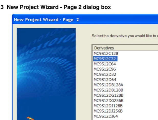
Let’s now rapidly create a project with CodeWarrior and analyze the assembly source and the Linker’s parameter files to calculate a Fibonacci series for a particular 16-bit microprocessor in the Freescale HC(S)12 family - in this case, the MC9S12C32.
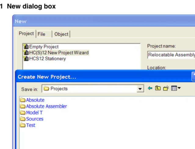
The New Project Wizard
Start the HC(S)12 CodeWarrior IDE application. Its path is:
<CodeWarrior installation folder>\bin\IDE.exe
Figure 1.1 New dialog box
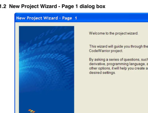
Figure 1.2 New Project Wizard - Page 1 dialog box
Figure 1.3 New Project Wizard - Page 2 dialog box
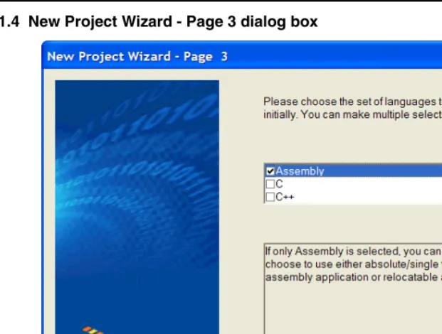
Figure 1.4 New Project Wizard - Page 3 dialog box
This is an assembly project, so HC(S)12 Assembly is the language. Check Assembly and be sure than C and C++ are unchecked. Press Next >. The New Project Wizard - Page 4
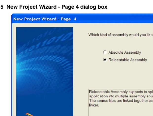
Figure 1.5 New Project Wizard - Page 4 dialog box
Select Relocatable Assembly. Although this project will only use one *.asm assembly source code file, it is more flexible to use relocatable assembly in case the project expands to include additional assembly source files. Because this project will use only one *.asm
file, the other option - Absolute Assembly - will be covered later in this chapter. The New Project Wizard - Page 5 dialog box appears (Figure 1.6 on page 25).
NOTE If an assembly project has two or more assembly source (*.asm) files, the
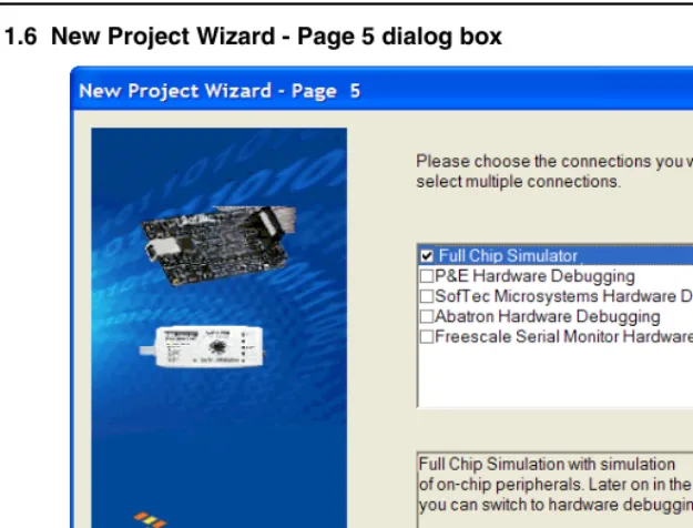
Figure 1.6 New Project Wizard - Page 5 dialog box
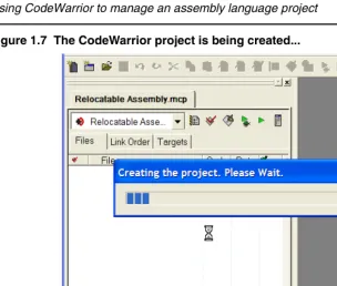
Figure 1.7 The CodeWarrior project is being created...
You can (but do it later) safely close the CodeWarrior IDE at any time after this point, and your project will be automatically configured in its previously-saved status when you work on the project later.
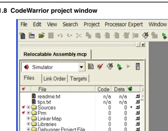
Figure 1.8 CodeWarrior project window
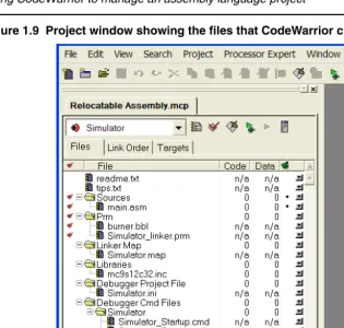
Figure 1.9 Project window showing the files that CodeWarrior created
You could use the Windows Explorer to examine the actual folders and files that CodeWarrior generated for your project and displays in the project window above, as in
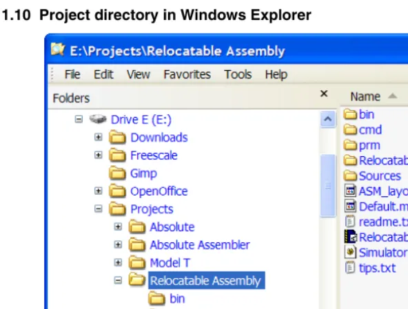
Figure 1.10 Project directory in Windows Explorer
The project directory holds a total of five subfolders and 16 files at this point. The major file for any CodeWarrior project is its <project_name>.mcp file. This is the file to reopen your project.
Figure 1.11 main.asm file in the project window
You can use this default main.asm file as a base to later rewrite your own assembly source program. Otherwise, you can import other assembly-code files into the project and instead delete the default main.asm file from the project. For this project, the
main.asm file contains the sample Fibonacci program.
Figure 1.12 Project window after a successful build
Notice that in the Code and Data columns in the project window show that the code size is 44 bytes and the data size is 4 bytes after assembling the main.asm file. If you checked the project directory after the first successful build (make) of the project with the Windows Explorer, you would see that another subfolder and five additional files were created. The new subfolder - ObjectCode - holds an object file for every assembly or C/C++ source code file. In this case, the main.asm.o file was generated.
Analysis of groups and files in the project
window
conveniently grouping files anyway you choose. You can add, rename, or delete files or groups, or you can move files or groups anywhere in the project window.
CodeWarrior groups
These groups and their usual functions are: • Sources
This group contains the assembly source code files. • Prm
This group holds the burner file and the Linker prm file. • Linker Map
This group has the Linker Map file. • Library
This group holds an include file. This project has an include file for the particular CPU derivative. In this case, the MC9S12C32.inc file is for the MC9S12C32 derivative.
• Debugger Project File
This group holds the project.ini file for configuring the debugger. • Debugger Cmd Files
A group with five debugger command files are located here.
NOTE The default configuration of the project by the Wizard does not generate an assembler output listing file for any *.asm file. However, you can afterwards select the Generate a listing file in the assembler options for the Assembler to generate a format-configurable listing file for the assembly source code and include files. Assembler listing files (with *.lst file extensions) are usually located in the bin subfolder in the project directory when *.asm files are assembled with this option set.
TIP To set up your project for generating assembler output listing files, select:
Writing your assembly source files
Once your project is configured, you can start writing your application’s assembly source code and the Linker’s PRM file.
NOTE You can write an assembly application using one or several assembly units. Each assembly unit performs one particular task. An assembly unit is comprised of an assembly source file and, perhaps, some additional include files. Variables are exported from or imported to the different assembly units so that a variable defined in an assembly unit can be used in another assembly unit. You create the application by linking all of the assembly units.
The usual procedure for writing an assembly source-code file is to use the editor that is integrated into CodeWarrior. You can begin a new file by pressing the New Text File icon on the Toolbar to open a new file, write your assembly-source code, and later save it with a *.asm file extension using the Save icon on the Toolbar to name and store it wherever you want it placed - usually in the Sources folder.
After the assembly-code file is written, it is added to the project using the Project menu. If the source file is still open in the project window, select the Sources group icon in the project window, single-click on the file that you are writing, and then select
Project > Add <filename> to Project. The newly created file is then added to the Sources
group in the project. If you do not first select the destination group’s icon (for example,
Sources) in the project window, the file will most likely be added to the bottom of the files and groups in the project window, which is OK. You can drag and drop the icon for any file wherever and whenever you want in the project window.
Analyzing the project files
We will analyze the default main.asm file that was generated when the project was created with the New Project Wizard. Listing 1.2 on page 33 is the default main.asm file that is located in the Sources folder created by the New Project Wizard.
Listing 1.2 main.asm file
;************************************************************** ;* This stationery serves as the framework for a * ;* user application. For a more comprehensive program that * ;* demonstrates the more advanced functionality of this * ;* processor, please see the demonstration applications * ;* located in the examples subdirectory of CodeWarrior for * ;* the HC12 Program directory. * ;************************************************************** ; export symbols
XDEF Entry, main
; allows us to reference 'Entry' either in ; the Linker *.prm file or from C/C++ later on. XREF __SEG_END_SSTACK ; symbol defined by the
; Linker for the end of ; the stack
; include derivative specific macros INCLUDE 'mc9s12c32.inc' ; variable/data section
MY_EXTENDED_RAM: SECTION
; Insert your data definition here. Counter ds.w 1
FiboRes ds.w 1 ; code section MyCode: SECTION main:
Entry:
LDS #__SEG_END_SSTACK ; initialize the stack pointer CLI ; enable interrupts
EndlessLoop:
LDX #1 ; X contains counter CounterLoop:
STX Counter ; update global. BSR CalcFibo
STD FiboRes ; store result LDX Counter
INX
CPX #24 ; Larger values cause overflow. BNE CounterLoop
BRA EndlessLoop ; restart
; Function to calculate Fibonacci numbers. Argument is in X. CalcFibo:
LDY #$00 ; second last LDD #$01 ; last
; loop once more (if X was 1, were done already) DBEQ X,FiboDone
LEAY D,Y
; exchange them -> order is correct again EXG D,Y
DBNE X,FiboLoop FiboDone:
RTS ; Result is in D.
When writing your assembly source code, pay special attention to the following: • Make sure that symbols outside of the current source file (in another source file or in
the linker configuration file) that are referenced from the current source file are externally visible. Notice that we have inserted the “XDEF Entry, main”
assembly directive where appropriate in the example.
• In order to make debugging from the application easier, we strongly recommend that you define separate sections for code, constant data (defined with DC) and variables (defined with DS). This will mean that the symbols located in the variable or constant data sections can be displayed in the data window component when using the Simulator/Debugger.
• Make sure to initialize the stack pointer when using BSR or JSR instructions in your application. The stack can be initialized in the assembly source code and allocated to RAM memory in the Linker parameter file, if a *.prm file is used.
NOTE The default assembly project using the New Project Wizard with CodeWarrior initializes the stack pointer automatically with a symbol defined by the Linker for the end of the stack “__SEG_END_SSTACK”.
NOTE An Absolute Assembly project does not require a Linker PRM file as the memory allocation is configured in the projects’s *.asm file instead.
Assembling your source files
Once an assembly source file is available, you can assemble it. You can either utilize CodeWarrior to assemble the *.asm files or alternatively you can use the standalone assembler that is located among the other Build Tools in the prog subfolder of the
<CodeWarrior installation> folder.
Assembling with CodeWarrior
• selecting one or more *.asm files in the project window and then select Compile
from the Project menu (Project > Compile). Only *.asm files that were preselected will generate updated *.o object files.
• select Project > Bring Up To Date. It is not necessary to preselect any assembly source files when using this command.
The object files are generated and placed into the ObjectCode subfolder in the project directory.
NOTE The target name can be changed to whatever you choose in the Target Settings
(preference) panels. Select Edit > <target_name> Settings... > Target > Target Settings and enter the revised target name into the Target Name: text box. The default <target_name> is Simulator.
Or, you can assemble all the *.asm files and link the resulting object files (and any appropriate library files) to generate the executable <target_name>.abs file by invoking either Make or Debug from the Project menu (Project > Make or Project > Debug). This results in the generation of the <target_name>.abs file in the bin
subfolder of the project directory.
Two other files generated by CodeWarrior after linking (Make) or Debug are:
• <target_name>.map
This Linker map file lists the names, load addresses, and lengths of all segments in your program. In addition, it lists the names and load addresses of any groups in the program, the start address, and messages about any errors the Linker encounters.
• <target_name>.abs.s19
This is an S-Record File that can be used for programming a ROM memory.
TIP The remaining file in the default bin subfolder is the main.dbg file that was generated back when the main.asm file was successfully assembled. This debugging file was generated because a bullet was present in the debugging column in the project window.
You can enter (or deselect by subsequently toggling) a debugging bullet by clicking at the intersection of the main.asm file (or whatever other source code file selected for debugging) and the debugging column in the project window. Whenever the Debugger or Simulator does not show a desired file in its Source
window, check first to see if the debugging bullet is present or not in the project window. The bullet must be present for debugging purposes.
TIP The New Project Wizard does not generate default assembler-output listing files. If you want such listing files generated, you have to select this option:
Edit > <target_name> Settings > Target > Assembler for HC12 > Options. Select the Output tab in the HC12 Assembler Option Settings dialog box. Check
Do not print included files in list file if you choose, but be advised that the include files for CPU derivatives are usually quite lengthy.) Now a *.lst file will be generated or updated in the bin subfolder of the project directory whenever a
*.asm file is assembled.
TIP You can also add the *.lst files to the project window for easier viewing. This way you do not have to continually hunt for them with your editor.
Assembling with the Assembler
It is also possible to use the HC(S)12 Assembler as a standalone assembler. (If you already have an assembled source file and prefer not to use the Assembler but do want to use the Linker, you can skip this section and proceed to “Linking the application” on page 50.) This tutorial does not create another project with the Build Tools, but instead makes use of a project already created by the CodeWarrior New Project Wizard. CodeWarrior can create, configure, and manage a project much easier and quicker than using the Build Tools. However, the Build Tools could also create and configure an entire project from scratch.
A Build Tool such as the Assembler uses a project directory file for configuring and locating its generated files. The folder that is set up for this purpose is referred to by a Build Tool as the “current directory.”
Figure 1.13 HC12 Assembler opens...
Read any of the Tips if you choose to and then press Close to close the Tip of the Day
dialog box.
Configuring the Assembler
A Build Tool, such as the Assembler, requires information from configuration files. There are two types of configuration data:
• Global
This data is common to all Build Tools and projects. There may be common data for each Build Tool (Assembler, Compiler, Linker, ...) such as listing the most recent projects, etc. All tools may store some global data in the mcutools.ini file. The tool first searches for this file in the directory of the tool itself (path of the
executable). If there is no mcutools.ini file in this directory, the tool looks for an mcutools.ini file located in the MS WINDOWS installation directory (e.g.
Listing 1.3 Typical locations for a global configuration file
\CW installation directory\prog\mcutools.ini - #1 priority C:\mcutools.ini - used if there is no mcutools.ini file above
For information about entries for the global configuration file, see
Global Configuration File Entries on page 399 in the Appendices. • Local
This file could be used by any Build Tool for a particular project. For information about entries for the local configuration file, see Local Configuration File Entries on page 409 in the Appendices.
[image:39.612.133.404.296.536.2]After opening the assembler, you would load the configuration file for your project if it already had one. In this case, you will create a new configuration file and save it so that whenever the project is reopened, its previously saved configuration state will be used. From the File menu, select New / Default Configuration. The HC12 Assembler Default Configuration dialog box appears (Figure 1.14 on page 39)
Figure 1.14 HC12 Assembler Default Configuration dialog box
dialog box appears. Navigate to the folder of your choice and create and name a folder and filename for the configuration file (Figure 1.15 on page 40).
Figure 1.15 Loading configuration dialog box
Press Open. The current directory for the HC(S)12 Assembler changes to your project directory (Figure 1.16 on page 40).
Figure 1.16 Assembler’s current directory switches to your project directory...
You now set the object-file format that you intend to use (HIWARE or
ELF/DWARF). Select the menu entry Assembler > Options. The Assembler displays the
[image:41.612.137.422.138.423.2]HC12 AssemblerOption Settings dialog box (Figure 1.17 on page 41).
Figure 1.17 HC12 Assembler Option Settings dialog box
In the Output panel, select the check boxes labeled Generate a listing file and Object File Format. For the Object File Format, select the ELF/DWARF 2.0 Object File Format in the pull-down menu. The listing file would be much shorter if the Do not print included files in list file check box is checked, so you may want to select that option also. Press OK to close the HC12 Assembler Option Settings dialog box.
Save the changes to the configuration by:
Input Files
Now that the project’s configuration is set, you can assemble an assembly-code file. However, the project does not contain any source-code files at this point. You could create assembly *.asm and include *.inc files from scratch for this project. However, for simplicity’s sake, you can copy and paste the Sources folder from the previous CodeWarrior project into the project directory (Figure 1.18 on page 42).
Figure 1.18 Project files
Now there are two files in the project:
• the project.ini configuration file and • main.asm in the Sources folder:
The contents of the main.asm file are displayed in Listing 1.4 on page 42.
Listing 1.4 main.asm file
;************************************************************** ;* This stationery serves as the framework for a * ;* user application. For a more comprehensive program that * ;* demonstrates the more advanced functionality of this * ;* processor, please see the demonstration applications * ;* located in the examples subdirectory of CodeWarrior for * ;* the HC12 Program directory. * ;************************************************************** ; export symbols
; We use 'Entry' as an export symbol. This ; allows us to reference 'Entry' either in ; the Linker *.prm file or from C/C++ later on. XREF __SEG_END_SSTACK ; symbol defined by the
; Linker for the end of ; the stack
; include derivative specific macros INCLUDE 'mc9s12c32.inc' ; variable/data section
MY_EXTENDED_RAM: SECTION
; Insert your data definition here. Counter ds.w 1
FiboRes ds.w 1 ; code section MyCode: SECTION main:
Entry:
LDS #__SEG_END_SSTACK ; initialize the stack pointer CLI ; enable interrupts
EndlessLoop:
LDX #1 ; X contains counter CounterLoop:
STX Counter ; update global. BSR CalcFibo
STD FiboRes ; store result LDX Counter
INX
CPX #24 ; Larger values cause overflow. BNE CounterLoop
BRA EndlessLoop ; restart
Assembling the Assembly source-code files
Figure 1.19 Select File to Assemble dialog box
Browse to the Sources folder in the project directory and select the main.asm file. Press Open and the main.asm file should start assembling (Figure 1.20 on page 44).
The project window provides positive information about the assembly process or generates error messages if the assembly was unsuccessful. In this case an error message is generated. - the A2309 File not found message. If you right-click on the text about the error message, a context menu appears (Figure 1.21 on page 45).
Figure 1.21 Context menu
Figure 1.22 A2309 error message help
You know that the file exists because it is included in the Sources folder that you imported into the project directory. The help message for the A2309 error states that the Assembler looks for this “missing” include file first in the current directory and then in the directory specified by the GENPATH environment variable. This implies that the
GENPATH environment variable should specify the location of the derivative.inc
include file.
NOTE If you read the main.asm file, you could have anticipated this on account of this statement on line 21: INCLUDE 'mc9s12c32.inc'.
Figure 1.23 Browsing for the Sources folder
Select the Environment tab and then General Path. Press the “...” button and navigate in the Browse for Folder dialog box for the folder that contains the missing file - the
include subfolder in the CodeWarrior installation’s lib folder. Press OK to close the
Figure 1.24 Adding a GENPATH
Press the Add button, and the path to the mc9s12c32.inc file
“{Compiler}\lib\hc12c\include” now appears in the lower panel. Press OK. An asterisk now appears in the Title bar, so save the change to the configuration by pressing the Save
button or by selecting File > Save Configuration. The asterisk disappears when the file is saved.
TIP You can clear the messages in the Assembler window at any time by selecting
View > Log > Clear Log.
Now that you have supplied the path to the derivative.inc file, let’s attempt again to assemble the main.asm file.
Select File > Assemble and again navigate to the main.asm file and press Open. After the GENPATH is set up for the include file, you can try to assemble the main.asm
Figure 1.25 Successful assembly - main.o object file created
Figure 1.26 Project directory after a successful assembly
The haphazard running of this project was intentionally designed to fail in order to illustrate what would occur if the path of any include file is not properly configured. Be aware that include files may be included by either *.asm or *.inc files. In addition, remember that the lib folder in the CodeWarrior installation contains several derivative-specific include and prm files available for inclusion into your projects.
So in the future, read through the *.asm files before assembling and set up whatever paths are required for any include (*.inc) files. If there were more than one *.asm file in the project, you could select any or all of them, and the selected *.asm files would be assembled simultaneously.
Linking the application
Once the object files are available you can link your application. The linker organizes the code and data sections into ROM and RAM memory areas according to the project’s linker parameter (PRM) file. The Linker’s input files are object-code files from the assembler or compiler, library files, and the Linker PRM file.
Linking with CodeWarrior
If you are using CodeWarrior to manage your project, a pre-configured PRM file for a particular derivative is already set up (Listing 1.5 on page 50).
Listing 1.5 Linker PRM file for the MC9S12C32 derivative
/* This is a linker parameter file for the MC9S12C32 */
NAMES END /* CodeWarrior will pass all the needed files to the
PLACEMENT below. */
RAM = READ_WRITE 0x0800 TO 0x0FFF; /* unbanked FLASH ROM */
ROM_4000 = READ_ONLY 0x4000 TO 0x7FFF; ROM_C000 = READ_ONLY 0xC000 TO 0xFEFF; /* banked FLASH ROM */
/* PAGE_3E = READ_ONLY 0x3E8000 TO 0x3EBFFF; not used: equivalent to ROM_4000 */
/* PAGE_3F = READ_ONLY 0x3F8000 TO 0x3FBFFF; not used: equivalent to ROM_C000 */
// OSVECTORS = READ_ONLY 0xFF8A TO 0xFFFF; /* OSEK interrupt vectors (use your vector.o) */ END
PLACEMENT /* All predefined and user segments are placed into the SEGMENTS defined above. */
_PRESTART, /* Used in HIWARE format: jump to _Startup at the code start */ STARTUP, /* startup data structures */ ROM_VAR, /* constant variables */ STRINGS, /* string literals */
VIRTUAL_TABLE_SEGMENT, /* C++ virtual table segment */ //.ostext, /* OSEK */
NON_BANKED, /* runtime routines which must not be banked */
DEFAULT_ROM,
COPY /* copy down information: how to initialize variables */
/* In case you want to use ROM_4000 here as well, make sure
that all files (incl. library files) are compiled with the option: -OnB=b */
INTO ROM_C000/*, ROM_4000*/; //.stackstart, /* eventually used for OSEK kernel
awareness: Main-Stack Start */ .stack, /* allocate stack first to avoid
overwriting variables on overflow */ //.stackend, /* eventually used for OSEK kernel
awareness: Main-Stack End */ DEFAULT_RAM INTO RAM;
//.vectors INTO OSVECTORS; /* OSEK */ END
ENTRIES /* keep the following unreferenced variables */
END
STACKSIZE 0x80
//VECTOR 0 _Startup /* reset vector: This is the default entry point for a C/C++ application. */
VECTOR 0 Entry /* reset vector: This is the default entry point for an Assembly application. */
INIT Entry /* for assembly applications: This is also the initialization entry point */
NOTE A number of entries in the PRM file in Listing 1.5 on page 50 are “commented-out” by the CodeWarrior IDE because they would not be utilized in this simple relocatable assembly project.
The Linker PRM file allocates memory for the stack and the sections named in the assembly source-code files. If the sections in the source code are not specifically referenced in the PLACEMENT section, then these sections are included in
DEFAULT_ROM or DEFAULT_RAM. You may use a different PRM file in place of the default PRM file that was generated by the New Project Wizard.
The Linker for HC12 preference panel controls which PRM file is used for your CodeWarrior project. The default PRM file for a CodeWarrior project is the PRM file in the project window. Let’s see what other options exist for the PRM file. From the Edit
Figure 1.27 Linker for HC12 preference panel
There are three radio buttons for selecting the PRM file and another for selecting an absolute, single-file assembly project:
• Use Custom PRM file (exists for backward compatibility) • Use Template PRM file (exists for backward compatibility) • Use PRM file from project - the default, or
• Absolute, Single-File Assembly project.
In case you want to change the filename of the application, you can determine the filename and its path with the Application Filename: text box. See the Smart Linker section of the “Build Tools” manual for details.
The ‘STACKSIZE’ entry is used to set the stack size. The size of the stack for this project is 80 bytes. The Entry symbol is used for both the entry point of the application and for the initialization entry point.
Linking the object-code files
You can run this relocatable assembly project from the Project menu: Select
Project > Make or Project > Debug. The Linker generates a *.abs file and a
Figure 1.28 Project directory in Windows Explorer after linking
The Full Chip Simulation option in CodeWarrior was selected when the project was created, so if Project > Debug is selected, the debugger opens and you can follow each assembly-code instruction during the execution of the program with the Simulator. You can single-step the simulator through the program’s assembly-source instructions from the
Run menu in the Simulator (Run > Assembly Step or Ctrl+F11).
Linking with the Linker
If you are using the standalone Linker, you will use a PRM file for the Linker to allocate memory.
• Start your editor and create the project’s linker parameter file. You can modify a
*.prm file from another project and rename it as <target_name>.prm. • Store the PRM file in a convenient location. A good spot would be directly into the
project directory.
• In the <target_name>.prm file, add the name of the executable (*.abs) file, say <target_name>.abs. In addition, you can also modify the start and end addresses for the ROM and RAM memory areas. The module’s Fibonacci.prm
file — a PRM file for an MC9S12C32 from another CodeWarrior project was adapted — is shown in Listing 1.6 on page 54.
Listing 1.6 Layout of a PRM file for the Linker - Fibonacci.prm
/* This is a linker parameter file for the MC9S12C32 */ LINK Fibonacci.abs
END
SEGMENTS /* All RAM/ROM areas of the device are listed. Used in PLACEMENT below. */
RAM = READ_WRITE 0x0800 TO 0x0FFF; /* unbanked FLASH ROM */
ROM_4000 = READ_ONLY 0x4000 TO 0x7FFF; ROM_C000 = READ_ONLY 0xC000 TO 0xFEFF; END
PLACEMENT /* All predefined and user segments are placed into the SEGMENTS defined above. */
ROM_VAR, /* constant variables */
NON_BANKED, /* runtime routines which must not be banked */
DEFAULT_ROM INTO ROM_C000/*, ROM_4000*/; .stack, /* allocate stack first to avoid
overwriting variables on overflow */ DEFAULT_RAM INTO RAM;
END
STACKSIZE 0x100
VECTOR 0 Entry /* reset vector: This is the default entry point for an Assembly application. */
INIT Entry /* for assembly applications: This is also the initialization entry point */
NOTE If you are adapting a PRM file from a CodeWarrior project, most of what you need to do is add object filenames that are to be linked in the LINK portion and
NAMES portion.
NOTE The default size for the stack using the CodeWarrior New Project Wizard for the MC9S12C32 is 256 bytes: (STACKSIZE 0x100). This command and
__SEG_END_SSTACK in the assembly code file determine the size and placement of the stack in RAM:
MyCode: SECTION main:
Entry:
The commands in the linker parameter file are described in the Linker portion of the Build Tools manual.
• Start the Linker.
The Smart Linker tool is located in the prog folder in the CodeWarrior installation:
proj\linker.exe
• Press Close to close the Tip of the Day dialog box.
• Load the project’s configuration file. Use the same <project>.ini that the Assembler used for its configuration - the project.ini file in the project directory:
[image:56.612.100.414.250.450.2]File > Load Configuration and navigate to the project’s configuration file (Figure 1.29 on page 56).
Figure 1.29 HC(S)12 Linker
• Press Open to load the configuration file. The project directory is now the current directory for the Linker. You can press the Save button to save the configuration if you choose. From the File menu in the Smart Linker, select Link: (File > Link
Figure 1.30 Select File to Link dialog box
Figure 1.31 Linker main window after linking
The messages in the linker’s project window indicate:
• The current directory for the Linker is the project directory,
E:\Projects\Fibonacci
• The Fibonacci.prm file was used to name the executable file, which object files were linked, and how the RAM and ROM memory areas are to be allocated for the relocatable sections. The Reset and application entry points were also specified in this file.
• There was one object-code file, main.o. • The output format was DWARF 2.0. • The Code Size was 46 bytes.
• A Linker Map file was generated - Fibonacci.map.
The Simulator/Debugger Build Tool, hiwave.exe, located in the prog folder in the CodeWarrior installation could be used to simulate the Fibonacci program in the
main.asm source-code file. The Simulator Build Tool can be operated in this manner: • Start the Simulator.
• Load the absolute executable file:
– File > Load Application... and browse to the appropriate *.abs file, or – Select the given path to the executable file, if it is appropriate as in this case
(Figure 1.32 on page 59):
E:\Projects\Fibonacci\Fibonacci.abs
Figure 1.32 HC(S)12 Simulator: Select the executable file
Figure 1.33 Assembly Stepping...
Directly generating an ABS file
You can also use CodeWarrior or the standalone assembler to generate an ABS file directly from your assembly source file. The Assembler may also be configured to generate an S-Record File at the same time. You can use the S-Record File for programming ROM memory.
When you use CodeWarrior or the standalone Assembler to directly generate an ABS file, there is no linker involved. This means that the source code for the application must be implemented in a single assembly unit and must contain only absolute sections.
Using CodeWarrior to generate an ABS file
You can use the Wizard to produce an absolute assembly project. To do so, you follow the same steps in creating a relocatable-assembly project given earlier. There are some differences:
• No PRM file is required, so no PRM file will be included in the Prm group in the project window.
• The memory area allocations are determined directly in the single *.asm assembly source-code file.
CodeWarrior project. However in the New Project Wizard - Page 4 dialog box, Absolute Assembly is selected. That is the only difference between relocatable and absolute assembly using the New Project Wizard (Figure 1.34 on page 61).
Figure 1.34 New Project Wizard - Page 4 dialog box
The single absolute-assembly main.asm file
Only one *.asm assembly source-code file can be used in an absolute-assembly project. The main.asm source code file differs slightly from a file used in relocatable assembly (Listing 1.7 on page 62).
Listing 1.7 main.asm file - absolute assembly
;***************************************************************** ;* This stationery serves as the framework for a * ;* user application (single file, absolute assembly application) * ;* For a more comprehensive program that * ;* demonstrates the more advanced functionality of this * ;* processor, please see the demonstration applications * ;* located in the examples subdirectory of the * ;* CodeWarrior for the HC12 Program directory * ;***************************************************************** ; export symbols
XDEF Entry ; export 'Entry' symbol
ABSENTRY Entry ; for absolute assembly: Mark this ; as the application entry point. ; include derivative specific macros
INCLUDE 'mc9s12c32.inc'
ROMStart EQU $4000 ; absolute address to place my code/constant ; variable/data section
ORG RAMStart ; Insert here your data definition. Counter DS.W 1
FiboRes DS.W 1 ; code section
ORG ROMStart Entry:
LDS #RAMEnd+1 ; initialize the stack pointer CLI ; enable interrupts
mainLoop:
LDX #1 ; X contains counter counterLoop:
STX Counter ; update global. BSR CalcFibo
STD FiboRes ; store result LDX Counter
INX
CPX #24 ; larger values cause overflow. BNE counterLoop
BRA mainLoop ; restart.
CalcFibo: ; Function to calculate Fibonacci numbers. Argument is in X LDY #$00 ; second last
DBEQ X,FiboDone ; loop once more (if X was 1, were FiboLoop:
LEAY D,Y ; overwrite second last with new va EXG D,Y ; exchange them -> order is correct DBNE X,FiboLoop
FiboDone:
RTS ; result in D
;************************************************************** ;* Interrupt Vectors * ;************************************************************** ORG $FFFE
DC.W Entry ; Reset Vector
Pay special attention to the following points:
• The Reset vector is usually initialized in the assembly source file with the application entry point. An absolute section containing the application’s entry point address is created at the Reset vector address. To set the entry point of the application at address $FFFE on the Entry symbol, the following code is used (Listing 1.9 on page 63):
Listing 1.8 Using ORG to set the Reset vector
ORG $FFFE
DC.W Entry ; Reset Vector
• The ABSENTRY directive is used to write the address of the application entry point in the generated absolute file. To set the entry point of the application on the Entry
label in the absolute file, the following code is used (Listing 1.9 on page 63).
Listing 1.9 Using ABSENTRY to enter the entry-point address
ABSENTRY Entry
Assembling main.asm
Listing 1.10 Assembler output listing file of main.asm
Freescale HC12-Assembler
(c) Copyright Freescale 1987-2005
Abs. Rel. Loc Obj. code Source line ---- ---- --- ---
---1 1 ;************************************ 2 2 ;* This stationery serves as the fram 3 3 ;* user application (single file, abs 4 4 ;* For a more comprehensive program t 5 5 ;* demonstrates the more advanced fun 6 6 ;* processor, please see the demonstr 7 7 ;* located in the examples subdirecto 8 8 ;* Freescale CodeWarrior for the HC1 9 9 ;************************************ 10 10
11 11 ; export symbols
12 12 XDEF Entry ; e 13 13 ABSENTRY Entry ; f
14 14 ; a
15 15
16 16 ; include derivative specific macros 17 17 INCLUDE 'mc9s12c32.inc' 5396 18
5397 19 0000 4000 ROMStart EQU $4000 ; absolute a 5398 20
5399 21 ; variable/data section
5400 22 ORG RAMStart ; I 5401 23 a000800 Counter DS.W 1
5402 24 a000802 FiboRes DS.W 1 5403 25
5404 26
5405 27 ; code section
5406 28 ORG ROMStart 5407 29 Entry:
5408 30 a004000 CF10 00 LDS #RAMEnd+1 ; i 5409 31 a004003 10EF CLI ; 5410 32 mainLoop:
5411 33 a004005 CE00 01 LDX #1 ; X 5412 34 counterLoop:
5413 35 a004008 7E08 00 STX Counter ; u 5414 36 a00400B 070E BSR CalcFibo
5415 37 a00400D 7C08 02 STD FiboRes ; s 5416 38 a004010 FE08 00 LDX Counter
5417 39 a004013 08 INX
5419 41 a004017 26EF BNE counterLoop
5420 42 a004019 20EA BRA mainLoop ; r 5421 43
5422 44 CalcFibo: ; Function to calculate Fi 5423 45 a00401B CD00 00 LDY #$00 ; s 5424 46 a00401E CC00 01 LDD #$01 ; l 5425 47 a004021 0405 07 DBEQ X,FiboDone ; l 5426 48 FiboLoop:
5427 49 a004024 19EE LEAY D,Y ; o 5428 50 a004026 B7C6 EXG D,Y ; e 5429 51 a004028 0435 F9 DBNE X,FiboLoop
5430 52 FiboDone:
5431 53 a00402B 3D RTS ; r 5432 54
5433 55
5434 56 ;************************************ 5435 57 ;* I
5436 58 ;************************************ 5437 59 ORG $FFFE
5438 60 a00FFFE 4000 DC.W Entry ; R
However, using the Bring Up To Date or Compile commands will not produce an executable (*.abs) output file. From the Project menu, select either Make or Debug
(Project > Make or Project > Debug) to generate the *.abs executable and
*.abs.s19 files in the bin subfolder. Be advised that it is not necessary to use the
Compile or Bring Up To Date commands used earlier to produce an assembler output listing file because using either the Make or Debug command also performs that functionality.
If you want to analyze the logic of the Fibonacci program, you can use the Simulator/ Debugger and assemble-step it through the program. If you select Project > Debug, the Simulator opens and you can follow the execution of the program while assemble-stepping the Simulator either from the Run menu in the Simulator (Run > Assembly Step
or Ctrl + F11).
Using the Assembler for absolute assembly
Create a new configuration project.ini file and directory for the absolute assembly project using the standalone Assembler Build Tool. This section does not go into the detail that was done for the relocatable assembly section. Use an absolute assembly source file of the type listed in Listing 1.11 on page 65.
Listing 1.11 Main.asm file for absolute assembly
; export symbols
XDEF Entry ; export 'Entry' symbol
ABSENTRY Entry ; for absolute assembly: Mark this ; as the application entry point. ; include derivative specific macros - RAMStart and RAMEnd data
INCLUDE 'mc9s12c32.inc'
ROMStart EQU $4000 ; absolute address to place my code/constants ; variable/data section
ORG RAMStart ; Insert here your data definition. Counter DS.W 1
FiboRes DS.W 1 ; code section
ORG ROMStart Entry:
LDS #RAMEnd+1 ; initialize the stack pointer to ; highest absolute RAM address CLI ; enable interrupts
mainLoop:
LDX #1 ; X contains counter counterLoop:
STX Counter ; update global. BSR CalcFibo
STD FiboRes ; store result LDX Counter
INX
CPX #24 ; larger values cause overflow. BNE counterLoop
BRA mainLoop ; restart.
CalcFibo: ; Function to calculate Fibonacci numbers. Argument is in X LDY #$00 ; second last
LDD #$01 ; last
DBEQ X,FiboDone ; loop once more (if X was 1, were FiboLoop:
LEAY D,Y ; overwrite second last with new va EXG D,Y ; exchange them -> order is correct DBNE X,FiboLoop
FiboDone:
RTS ; result in D
Figure
Related documents