IP Based Navigational Status Display System
Mrs. Sudha R1, Mr. Abishek H2, Mr. Aswin J3, Mr. Amudha Bharathi M4, Mr. Dhinesh Babu S5
1, 2, 3, 4, 5
Electronics and Communication Engineering, Anna University
Abstract: Airports generally make use of Navigational Aids to guide the pilot to properly land the aircraft when close to the runway. These NAV-AIDS send out electric signals to determine the status of the aircrafts. The CNS department at the airport collects these signals from each Navigational Aid and transmits them to a centralized station. Here, suitable algorithms are deployed to decipher the status with respect to each NAV-AID, from the payload. This system makes use of MQTT standard that works on the TCP/IP protocol to, carry out the technical procedures.
Keywords: Navigational Aids, ESP8266, MQTT, Optocoupler, Light Emitting Diode.
I. INTRODUCTION
A. Navigational Aids
A navigational aid (also known as aid to navigation, ATON, or NAV-AID) is any sort of marker which aids the traveller in navigation, usually nautical or aviation travel. Common types of such aids include lighthouses, buoys, compasses, fog signals and day beacons. It is any visual or electronic device, airborne or located on a surface that allows the pilot to fix his position or otherwise guides him in navigating the aircraft in flight, while landing or in taking off. A NAV-AID may be pilot-interpreted or ground- interpreted. On charts, NAV-AID information boxes contain the NAV-AID name, identifier, frequency, and Morse code. They are usually depicted on electronic charts.
Airports Authority of India (AAI) provides Air Navigational Services over the Indian continental Airspace and adjoining oceanic areas in accordance with ICAO Standards and Recommended Practices. In the process of fulfilling its commitments towards safe and efficient Air Navigation Services, AAI has installed and maintained CNS (Communication, Navigation & Surveillance) systems at various airports and en route stations. The parameters and health status of these facilities are continuously monitored by skilled Technical Personnel of Airports Authority of India. Some of the most important Navigational Aids used are, DVOR, DME, ILS, LLZ and NDB. These devices are usually located along the runway at regular intervals. Their operational status is extended to the various Air Traffic Units in the airport, in order to make sure that any failure of facility is immediately provided for information and necessary action to the Airport Personnel. In view of continuous monitoring and surveillance, these devices are frequently updated and registered. The signal status of each Navigational Aid is carried out by Remote Status Units (RSUs) from the runway to the centralized station.
B. Instrument Landing System
An Instrument Landing System enables a pilot to conduct an instrument approach to landing an aircraft if it is difficult to establish visual contact with the runway. An ILS is mainly comprised of two subsystems: The localizer that provides lateral guidance, the glide scope that provides vertical guidance. It is defined as a station service, by the International Telecommunication Union. An ILS is ground-interpreted instrument approach system that provides precision lateral and vertical guidance to an aircraft that is about to land on a runway. It employs a combination of radio signals and lighting arrays to ensure safe landing, even during strong weather conditions such as fog, rain or blowing snow. An instrument approach procedure chart is published for each ILS to provide the regulations based on which instrument flight rules (IFR) is to be operated. An electronic chart includes the radio frequencies used by the Navigational Aids under prescribed minimum visibility requirements. An aircraft approaching a runway is guided by the ILS receivers by means of modulation depth comparisons. The signals given out by an ILS can be directed into the autopilot to fly the approach automatically.
II. EXISTING SYSTEM
representation of information to make that information more easily understood and to allow decisions to be made correctly and promptly. The Radio Navigational Aids documentation consists of a detailed list of selected worldwide radio stations that provide services to the pilot. The publication is divided into sections according to the nature of service provided by the radio stations. The accessible services are radio direction finder, radar stations, broadcasting navigational warnings, time signals or medical advice. It also helps with communication traffic for distress, emergency and safety including the long range navigational aids. The content is also flooded with information related to the chapters describing procedures of the Automated Mutual-Assistance Vessel Rescue System, interim emergency procedures and communication instructions to be followed in times of crisis. Air Services has released an updated Fact Sheet: Noise Abatement Procedures for Gold Coast Airport. These regulations will ensure that alternative flight paths are used in preference to the ILS. The Administrative Appeals Tribunal (AAT) is a body that provides conditions requiring the Air Services to design NAPs to minimize the usage of the ILS under situations where poor weather conditions were prevalent affecting, visibility for operational requirements, and during emergencies. Moreover, status of NAV-AIDS is displayed at the Air Traffic Service Units through separate individual Remote Status Units. Each RSU derives the operational status separately by respective Remote Control & Status Units (RCSU) of navigational aids which is installed in the Equipment Room connected to Equipment site through Remote Control Cables.
But, the constraints of the present system are:
1) RCSU at equipment room can drive a limited number RSUs at various Air Traffic Service Units.
2) Different makes/models of the NAV-AIDS have their own system of RCSU & RSU and, cannot be interchangeably used.
3) At Air Traffic Service Units, status is not displayed in a collective manner and separate RSUs are required to be provided for NAV-AID facility. These RSUs consume a large amount of space at various Air Traffic Service Units especially at Control Tower.
4) Only a limited number of ATC working positions can be catered by RSUs and system is not extensible/flexible.
5) Visual Status Display provided by RSU is not proper and not integrated with the Controller Working Position. Due to installation of ATM Automation Systems and subsequent to Upper Airspace Harmonization/Sectorization there is a need of displaying and navigational aids status to all the Controller Working Position in an integrated manner and status provided should be integrated at CWP with other HMI(s).
6) System is hardwired i.e. separate signal cables are running from Equipment room to the ATC working position, hence difficult to manage. Distance up to which RCSU can drive RSU is also limited due to hard wiring.
III.PROPOSED SYSTEM
A. IP Based Navigational Status Display System
This system is proposed with an intent to overcome all the drawbacks of the existing system. The proposed system will collect the status of different NAV-AIDS facility from their respective RCSUs at Equipment room, integrate it, transmit it on a LAN and display the status in a collective manner at different ATC working positions as required. The system shall be easy to manage flexible and independent devices irrespective of the model/make, keeping in mind, the operationality of the NAV-AIDS. The system shall be based on commercially available industrial standard equipment that generally uses Programmable Logic Controllers/Encoders, Decoders and High Resolution-HMI Displays with standard Modbus signalling over RS485 & Ethernet.
1) The proposed IP based Navigational Aid Status Display System shall be provided at various ATC Working Positions (Consoles) installed as part of ATS Automation Systems at Airports. The status indications for the controllers are to be provided for the Navigational Aids such as ILS, LLZ, GP, GP (DME), DVOR/DME, NDB, Locators and Markers.
2) The system shall basically consists of Encoders/PLCs, Decoders, with status indicator panels (High Resolution HMIs) to provide a visual indication at the Air Traffic Controller working positions (Consoles) at various locations for the provision of status of availability/non availability of particular Navigational Facility operational at an airport from a remote location. The status indicator panel with decoder of required size is to be fitted on the ATC consoles provided for ATC Automation System at Airports.
4) There are many similar data for each of the Navigational Aids (Localizer, Glide Path, LP/DME, OM, OL, DVOR, DME, etc.) provided through respective Remote Control and Unit of the facility.
5) This data is collected, integrated and transmitted as encoded Modbus data over RS485 signals through a pair of shielded audio cable to the decoder/display module (HMI) located at the Air Traffic Controller Console positions for providing integrated STATUS indication.
6) The Navigational Status display system shall be of two components: The Microcontroller and The Decoder integrated with display module (HMI).
7) The Microcontroller shall be positioned at the Main Equipment Hall, from where the maintenance officers will monitor.
[image:3.612.135.471.262.358.2]8) The Decoder/Display (HMI) unit shall be positioned at a number of Air Traffic Controller operational positions (Consoles). The decoder with status indication panel shall be mounted at a pre-defined slot on the console.
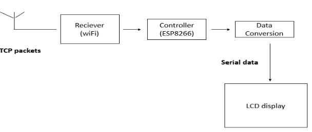
Fig. 1 The block diagram of the proposed system’s transmitter
There is an input electrical signal of 5V is fed to the optocoupler from the Navigational Aids. The optocoupler provides basic isolation from power surges (input signal). The optocoupler produces a 3V electrical output. After proper isolation is ensured, this signal is converted to the corresponding TCP packets and sent to the LAN via MQTT protocol. This establishes a basic communication platform between the ESP8266 from the transmitter’s circuit and that from the receiver’s circuit. It must be ensured that a constant internet connection is available to sustain this connection. The ESP8266 is a Wi-Fi Module that actually allows conversion of the electrical signals into TCP data packets before transmission.
The receiver is also a Wi-Fi Module which communicates with the sender over LAN and displays the signal status through the LED. Here, the ESP8266 converts the data packets back into electrical signals and they are now displayed on the electronic charts.
[image:3.612.160.464.571.700.2]IV.RESULT
[image:4.612.167.457.156.327.2] [image:4.612.142.473.549.721.2]Though, TCP/IP is not best suited for IoT applications due to packet overheads, still being the most common protocol stack on internet, it offers ubiquitous connectivity. An IoT device can be made to communicate with a cloud or server using TCP/IP protocol without the bother of network programming and network administration. In this project, a Wi-Fi Module will be designed that could transmit sensor data to the receiver platform which is yet another Wi-Fi Module using the TCP/IP protocol. Here, the ESP8266 is used as the Wi-Fi Module.
Fig. 3 Snapshot of the output’s sender part.
The ESP8266 designed in this project is exercised in a way that it acts both as a transmitter as well as a receiver. This reduces the complexity of the entire circuitry used with the added fact that, a bidirectional communication can be witnessed although, not simultaneously. The ESP8266 is a microcontroller board that can connect to an internet network on its own. For internet connectivity, the ESP8266 Fi Module uses a self-contained SoC with integrated TCP/IP protocol stack that can access to a Wi-Fi network. The ESP module allows any device to connect to a router and access internet network. In view of monitoring a secure and swift transmission, many technologies have been implemented at the airport. It is to be understood that, the signal status of Navigational Aids when distributed to the various stations, makes it easier for the technical supervisors and other personnel to careful observe the movement of aircrafts close to the runway. This evolution is now at the intersection of sensing, protection and communication technologies, providing the unique opportunity to develop a more reliable and maintainable communication system. The IP based Navigational Status Display System overcomes all the drawbacks and major setbacks experienced with the existing system. With a TCP/IP connection, the security is enhanced as, a local broker can be installed at the airport, making it available and accessible only to the airport personnel. The status of the different NAV-AIDS from their respective RCUs at the Equipment Room (Centralized Station) is integrated and, transmitted over a LAN. A collective display system presents the status in a collective manner at different ATC working positions as required. Now, a miniature prototype of this large scale extrapolation is executed wherein, 5V signals are generated using an ARDUINO-UNO. These signals are fed to the ESP8266 through connectors.
As mentioned in the earlier sections, the Wi-Fi Module proctors the signals and observes the status. All of this is taken care by the transmitter. The circuitry mostly consists of an ESP8266, connectors, a few resistors and optocouplers. This is exactly where the MQTT protocol comes into picture. The Wi-Fi module used at the transmitter’s side acts as the server/broker. It is capable of connecting to the different receivers available across the network. This proves that the use of Wi-Fi Modules has made it easier and efficient to implement the concept of dissemination of data. The receiver’s circuitry is pretty simpler when compared to the broker’s connection. LEDs are used to indicate the detection of the Navigational Aids at the different terminals along the runway. The signal status of each Navigational Aid is not just observed through the LEDs but, a computerized terminal is also capable of determining the status of each NAV-AID. Here, the On/Off condition is witnessed by the use of binary digits. 1 indicates the On state whereas,0 indicates the Off state. A more detailed explanation can be observed through the diagram. As shown above, it can be seen that the status of each NAV-AID is expressed in the form of binary values. This makes it easier to distinctly identify the position of the aircraft when it is hovering over the runway.
V. CONCLUSION
Though, GPS has made a prominent place in the world of technology, airports still use Navigational Aids at the airport. A few reasons can be because they serve as the sources for IVSI, flight path vectors, trend vectors, wind calculations, wind shear detection, etc. They also are capable of providing display with altitude information. Moreover, a GPS tends to glitch out or become inaccurate when aircrafts are in close proximity to high terrain such as The Alps, Rocky Mountains, Pyrenees, etc. A few improvements can be brought to this proposed system through the incorporation of Required Navigation performance in the Navigational Aids.
This allows the aircraft to fly a specific path between two 3D-defined points in space. Nevertheless, scientists are still sceptical about morphing the existing products for it may lead to further complications. But, with the promise of improved on-board performance and monitoring, any device with an RNAV specification can be overridden. Inspired by a 2011 white paper, the ICAO published in November 2018 the Establishment of RNP-Authorization Required (EoR) standard to reduce separation for parallel runways, improving traffic flow while reducing noise, emissions and distance flown.
VI.ACKNOWLEDGEMENT
In attempt to complete this project many people have graciously extended their guidance, knowledge and criticism to improve our work.
We sincerely express our deepest gratitude to Dr. S. THANGAVELU, Mr. T. DEEPAN, Secretary, SSIET for his encouragement and also to Mr. T. SHEELAN, Joint secretary, SSIET for their continuous encouragement and support throughout our course of study.
We would like to express our gratefulness to our Principal, Dr. PRAKASH for his magnanimity in allowing us to avail the facilities in this department.
We hereby acknowledging and express our deep most and sincere gratitude to Dr. B.VINODH KUMAR, Professor and Head of the Department, Department of Electronics and Communication Engineering for his continuous encouragement and support in carrying out the project work.
We would like to offer heartfelt thanks to our project coordinator Mrs. S YOGITHA, Assistant Professor and our project guide Mrs. R SUDHA, Professor of ECE Department for her valuable technical discussions and guidance during the project work.
We acknowledge our thanks to the teaching and non-teaching staff of our department, our beloved parents and friends, for their help provided during the development of our project.
REFERENCES
[1] https://ieeexplore.ieee.org/document/7906845
[2] https://ieeexplore.ieee.org/document/7917998
[3] https://iotbytes.wordpress.com/nodemcu-pinout/