Load Diode
Source
Electronic Design Automation Tool: a Comparative
Study
Poonam Dang1, Harshal Arolkar2
1
FCAIT-GLSU , 2FCT- GLSU
Abstract: Teaching and evaluation of questions related to computer programming, circuit designing, mathematical problems is a critical part in engineering courses. Lot of efforts and time needs to be put by the faculties to teach and evaluate such domains. The questions in this domain are considered to be logical and hence can be solved in multiple ways. In this scenario, evaluation becomes significantly more complex and hence more time consuming and tricky. After conducting an exam of 2 hours, faculty at times need to spend more than 5 to 6 hours to evaluate the submission properly. This takes huge efforts as well as lot of time is consumed to intimate the result. Circuit design is a one of the most common subject in engineering courses. Creation of physical circuits using hardware and testing their validity is expensive and time consuming for students as well as faculties. Alternative teaching method for creation of circuit is virtualization of hardware activities into software solutions. One such solution is EDA tool. An Electronic Design Automation (EDA) tool serves as a learning, experimentation and evaluation tool in teaching-learning environment. These modern electronic design methods help faculties and students to draw and simulate circuit designs effortlessly. Once a circuit has been designed, it can be saved and tested multiple times, with different inputs to check its validity.
In this research paper, we have done comparative study of three most widely used EDA tools namely QUCS, LT Spice and e-Sim.
Keywords: EDA, Rectifier, QUCS, LTspice IV, OSCAD
I. INTRODUCTIONTOEDA(ELECTRONICDESIGNAUTOMATION)TOOLS
Electronic chip designing is one of the complex tasks for chip designers. A prototype chip created using hardware involves high cost and at times high failure rates too. Today it is possible to simulate the design of a chip using computer and proper software tools. Electronic Design Automation is an approach, where a software tool used to design and simulate the working of an electronic circuit[2]. An EDA tool allows creation of proper engineering electronic design. The circuit designs creates a designs, simulates it, corrects problem if needed and implement the design. It provides flexibility and reduces the work of designer. EDA tool thus has a huge potential usage in teaching of circuit design. It can be used by teacher and student for simulating and evaluating a circuit design. In this research paper, we have studied some existing EDA tools. By doing this, we hope that this work would help other researchers to identify the strengths and weakness of different EDA tools compared here. The comparison has been done by simulating a half wave rectifier circuit design in different EDA tools. The circuit that has been simulated in this paper is half wave rectifier. The half wave rectifier is used to convert AC voltage to DC voltage. As electronic devices work on the DC voltage supply only, rectifiers are used in all electronic devices. Half wave rectifier is used to rectify only half cycle of the waveform. In the simulation scenario, AC input is given to the rectifier circuit. These inputs are for positive and negative cycles. The half wave rectifier works only on positive half cycle. It omits negative cycle. Fig. 1 shows the half wave rectifier circuit design.
Circuit simulation shows the behaviour of electronic devices or circuits. Traditionally, electronic circuits were modelled and simulated using special-purpose electronic circuit simulators. Although a number of such simulation tools have been made available over the years, the one tool that has been most successful in conquering the market is SPICE (Simulation Program with Integrated Circuit Emphasis) [1]. SPICE was released in 1972 by the University of California at Berkeley. It is a general-purpose circuit simulator. It can simulate broad range of circuit families, circuit sizes, and has many analysis options. Today over 10,000 copies of the program are in use world-wide, making it without doubt the most successful single program for electronic circuit design ever developed. SPICE simulator describes device models and circuit data in text format called netlist.
III.SIMULATIONOFHALFWAVERECTIFIERUSINGEXISTINGEDATOOLS
EDA tools like KiCAD, Logisim, ORCAD, PSPICE, NGSPICE and many more are widely used in academic environment. Each EDA tool has its own interface and working methodology. In this section we have discussed the characteristics, interface, input file format, output file format and simulation scenario of QUCS, LTspice IV and eSim EDA tools.
A. Quite Universal Circuit Simulator (QUCS)
The Quite Universal Circuit Simulator (QUCS) [4] is an educational and open source software program. It helps to generate schematic diagrams and check their performance. It has vital component library which includes lumped components, sources, probes, transmission lines, nonlinear components, digital components, various simulations, file components, diagrams and paintings. It takes a netlist file, checks it for errors, performs the required simulation actions, and finally produces a dataset. Simulation data
can be represented in various types of diagrams, including Smith-Chart, Cartesian, Tabular, Polar, Smith Polar combination,
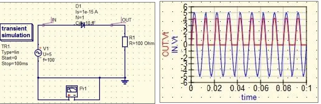
3D-Cartesian, Locus Curve, Timing Diagram and Truth Table. It uses FreeHDL and Icarus Verilog for VHDL and Verilog digital simulation respectively. Qucsator simulation engine is used for simulation of circuit designs in QUCS. SPICE netlists can be read and simulated by QUCS using conversion program Qucsconv. Recent version Qucs-0.0.19/S is compatible with ngspice and Xyce. It has spice4qucs structure which helps to simulate spice netlist format circuits. ngspice and Xyce are an open source spice compatible analog circuit simulator. Fig. 2 shows transient simulation of half wave rectifier. Fig. 3 shows half wave rectifier simulation using QUCS. In the Fig. 3 blue coloured signal is input while red coloured signal is output. In this diagram AC Voltage source with 5v and frequency=100Hz has been applied. Ideal diode and a load register with 100ohm are used. Labels "IN" and "OUT" are used for the input and output sides of the circuits. To simulate circuit transient analysis is used. In transient analysis, dataset contains voltage or current information over time. The start time of the transient simulation is set to 0 and the stop time to 100ms which will include 100 periods of the input signal. Fig. 3 shows peak output voltage 4.2 V due to the voltage drop 0.8V at diode while Fig. 4 shows same in .csv format. This .csv file can be used for evaluation of circuit design. Fig. 5 show the netlist file of half wave circuit design using QUCS. This file includes list of components which are taken in circuit design and interconnection information of components. QUCS cannot directly simulate standard SPICE circuit netlists but requires them to be converted to their QUCS equivalent prior to simulation.
[image:2.612.43.561.514.683.2]
Fig. 4 .csv file of simulated data of half wave circuit design using QUCS
Fig. 5 Netlist file of half wave circuit designed using QUCS
B. LTspice IV
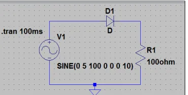
[image:3.612.208.393.634.728.2]Fig. 6 Transient simulation of half wave rectifier using LTspice
Fig. 7 Transient simulation of circuit design using LTspice
Fig. 8 .txt file of simulated data of half wave circuit design using LTspice Fig. 9 Netlist file of half wave circuit design
C. eSim (OSCAD)
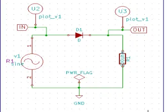
[image:4.612.215.380.616.727.2]Fig. 10 Half wave rectifier schematic design using eSim
[image:5.612.102.518.375.645.2]Fig. 11 Transient simulation of half wave rectifier using eSim Fig. 12 .txt file of simulated data of half wave circuit using eSim
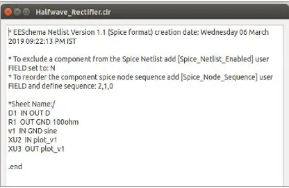
Fig. 13 Netlist file of half wave circuit design using eSim
IV.COMPARISONOFEDATOOLS
TABLEI
COMPARISON OF EDATOOLS
Types of Components QUCS LTspice IV eSim(OSCAD)
Passive Components (Register, Capacitor, Inductors, etc.)
Yes Yes Yes
Active Components (Diodes, Transistors, ICs)
Yes Yes Yes
Sources (Current and Volatge) Yes Yes Yes
Digital Components
AND, OR, XOR, NOT Gates Yes Yes Yes
NAND, NOR, XNOR Gates Yes No Yes
SR and D Flipflops Yes Yes Yes
JK, T Flipflops Yes No Yes
VHDL Files Yes No No
Verilog Files Yes No No
Analysis Types
Transient Yes Yes Yes
AC Yes Yes Yes
DC Yes Yes Yes
Digital Yes
(FreeHDL Packege Required)
Yes (not used for complex)
Yes
Harmonic balance Yes No No
S-Parameter Yes Yes No
Parameter Sweep Yes No No
Noise Yes Yes No
Optimization Yes No No
Subcircuit Simulation Yes Yes Yes
Others
Runs on Windows? Yes Yes No
Open Source tool Yes No Yes
Other Platforms? Linux, Solaris,
Mac
For linux Wine required
Linux
Spice Netlist Format No
QUCS Netlist Format
Yes Yes
PCB Creation No No Yes
Web App No No Yes
Circuit Equations for each simulation step
No No Yes
Check ERC No No Yes
BOM (Bills of Materials) No Yes Yes
After comparing the tool we have following observations. QUCS and SPICE differ significantly in their representation of circuit netlist file formats. QUCS does not generate standard SPICE netlist file as an output. The QUCS netlist files generated are difficult to understand and cannot be directly simulated on other simulators. Further it cannot be used design PCB also. It also does not provide web view. Hence it is not integrated directly to web view. Additionally for performing digital simulation third party HDL packages are required. Erroneous connections cannot be directly identified by using ERC check rule.
LT spice is used more for analog circuit designs. It has very few digital components hence it is not used for complex circuit design. Also it cannot be extended by researchers as source code is not available although usage is free. It has a constraint of platform as it is majorly used as window operating system.
eSim supports few types of analysis like AC, DC and Transient. Hence exhaustive circuit analysis cannot be done. It supports webapp hence it can be integrated into a website for creation of a virtual lab.
V. CONCLUSIONS
We have compared EDA tools using different parameters and a result is available in table 1. All the tools analyzed have proper GUI which can be easily understood and used by students as well as faculties for designing and testing analog circuits. From this paper we can conclude that it is a good option to use simulation techniques for the purpose of designing and testing new analog circuits. There is a still scope of new EDA tool that can perform more analysis as compared to the existing once.
REFERENCES
[1] Colin Warwick, Everything you always wanted to know about SPICE - But were afraid to ask, The EMC Journal May 2009 - Issue 82, Page 27-29. ISNN 1748-9253
[2] Dewey, A. , "Digital & Analog Electronic Design Automation", The electrical engineering handbook, CRC Press LLC, 2000. [3] J.-P. Charras and F. Tappero. (2013, May). [Online]. Available: http: //www.kicad-pcb.org/display/KICAD/KiCad+Documentationvv
[4] M. E. Brinson, R. Crozier, V. Kuznetsov, C. Novalk, B. Roucaries, F. Schreuder, G. B. Torri, "QUCS: An Introduction to the new simulation and compact device modelling features implemented in release 0.0.19/0.0.19Src2 of the popular GPL circuit simulator. ", MOS-AK Workshop, Graz, Sep. 2015.
[5] P. Nenzi and H. Vogt. (2013) Ngspice users manual version 25plus. [Online]. Available: http://ngspice.sourceforge.net/docs/ngspice-manual.pdf [6] Prasad, Guru (2016), Circuit Simulation Examples using LTspice, available on Research Gate