Twelve Pulse Inter Line Power Flow Controller
G. Sridhar Babu1, Dr. N. Ram Chandra2, G. Rohith Reddy3
1,2, 3
EEE Department, St. Martins Engineering College, Secunderabad, Telangana, India.
Abstract: Inter line power flow controller (IPFC) is a FACTS device which simultaneously controls the power flow in multiline systems. The major work of IPFC is to maintain or improve power flow and voltage profile at the receiving end of transmission system without burdening the generation system. The major part in construction of IPFC is designing of control technique for the converter placed in IPFC. There are different types of control techniques. In this paper we proposed the latest control technique i.e. SVPWM (Space Vector Pulse Width Modulation) which is implemented in 12 pulse voltage source inverter. By using IPFC-SVM different case studies and analyzed.
Keywords- 12 pulse converter, Inter line power flow controller (IPFC), control techniques, Space vector modulation
I. INTRODUCTION
With the increase in applications of nonlinear and electronically switched devices and industries, power quality (PQ) problems, such as harmonics, imbalance have become serious concerns. In addition to these there are several others causing PQ problems are, lightning strikes on lines, switching of capacitor banks etc., in order to meet PQ standard limits, we need to include some sort of compensation. In recent years, solutions based on flexible ac transmission systems (FACTS) have appeared. In this context, very fast reactive compensators, electronically controlled, and power flow controllers have been developed within the overall framework of the Flexible AC Transmission systems (FACTS) initiative [1]. The primary function of FACTS is to control power flow in transmission lines, the secondary functions can be voltage control, transient stability improvement and oscillation damping [2].The most versatile and powerful devices, which help in improving the transfer capability of transmission lines are FACTS devices. Among these, FACTS controllers using the self-commutated voltage sourced converters (VSC) [3], unified power flow controllers (UPFC) and interline power flow controllers (IPFC) are the latest generation FACTS controllers. Recently, multi converter FACTS devices, such as IPFC [8] and generalized unified power flow controller (GUPFC) [9] are introduced. The aim of these is to control power flow of multi lines rather than Control of power flow of single line by, for instance, a UPFC UPFC is a series-shunt controller. It has the combined function of both series and shunt compensation, it is capable to control both active and reactive power flows in transmission line [4]. It is used in power flow control, load shearing, voltage regulation and improve transient stability. In GUPFC since the source impedance is very low, a high amount of current would be needed to boost the bus voltage in case of a voltage sag or swell which is not feasible. In this paper a power flow management in interline (IPFC), capable of simultaneous compensation for voltage and current in multi-line system is presented. The proposed system can be used for compensation of both current and voltage imperfections.
II. POWER QUALITY PROBLEMS
We shall define power quality problem as: ‘any power problem that results in failure or mis-operation of customer equipment manifests itself as an economic burden to the user, or produces negative impacts on the environment.’
A. power Issues Which Degrade Power Quality Include 1) Power factor
2) Harmonic distortion
3) Voltage transients
4) Voltage sags or dips
5) Voltage swells
B. Power Quality Can be Improved Through 1) Power factor correction
2) Harmonic filtering
3) Special line notch filtering
III. INTRODUCTION TO FACTS
FACTS are well known for higher controllability in power systems by means of power electronic devices. Several devices have been introduced for various applications
A. The basic applications of FACTS Devices Are 1) Power flow control
2) Voltage control
3) Stability improvement
4) Reactive power compensation
5) Increase transmission capability
6) Power quality improvement
7) Power conditioning
8) Flicker mitigation
9) Interconnection of renewable and distributed generation and storages.
IV. ROLE OF FACTS DEVICES
A. The Benefits Of Employing Facts Are Mainly
1) power quality by power profile and voltage profile improvement
2) very fast control response time improvement of the dynamic and transient stability
3) voltage stability with security improvement
4) less power loss and efficiency
5) increasing power flow capability
6) voltage regulation of power system
7) phase control feasibility in individual phase
8) low maintenance requirement, since no rotating parts
B. Basically Controllers Are Divided into Following Categories 1) Series controllers like TCSC, TSSC, and SSSC etc.
2) Shunt controllers like STATCOM, SVC etc.
3) series shunt controllers like UPFC
4) series-series controllers like IPFC
V. ROLE OF IPFC IN FACTS
It is back to back connection of two SSSCs installed in two or more lines and connected at their DC terminals. Thus in addition to serially compensate the reactive power, each SSSC can provide real power to the common DC link from its own line. IPFC has the capability of controlling different transmission lines at a determined substation. It has the capability of transfer of power between under loaded and over loaded lines. Under-utilized lines make available surplus power which can be used by other lines for real power control. This ability of IPFC makes it
A. possible to equalize the flow of active and reactive power flow between the lines
B. helps in transfer of power demand from over loaded to under loaded lines,
C. compensate against resistive line voltage drops and corresponding line reactive power
D. increases the effectiveness of the system against dynamic disturbances
Therefore IPFC provides highly effective scheme for power transmission in a multi-line substation. IPFC is a multi-line FACTS device [5].
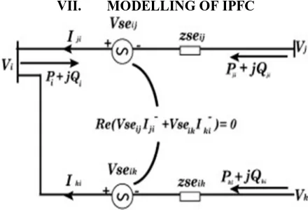
VI. OPERATING PRINCIPLE OF IPFC
Figure 1. Basic configuration of IPFC
Basic IPFC consists of two DC to AC, back to back connected converters, which are in series with the transmission line through series injection transformers and the DC terminals are connected through a common DC link. Thus in addition of providing reactive power compensation it also helps in supplying real power to the common DC link from its own transmission line [7].
A. Basic Power Flow Equations
S
p*
V
p*I
q (1) Where S – apparent powerV-voltage of a particular bus I-current in the transmission line
From equation 1 active and reactive power flow equations can be written as
n j
pq q p pq q p p
V
V
V
P
1
)
cos(
(2)
n j
pq q p pq q p q
V
V
V
Q
1
)
sin(
(3)Where
p
j p p
V
e
V
---voltage at bus Pq
j q q
V
e
V
---voltage at bus qpq
j pq pq
Y
e
Y
---admittance for transmission line p-q [image:3.612.195.415.569.719.2]The complex power injected by converter 1 is given by
1 1
1 se se
se
P
jQ
S
(4)
1 1 1 1 1 1 1 1 se i j se se i se se sejX
V
V
i
V
V
S
(5)The active power injected by converter 1 is given by:
)
90
cos(
)
90
cos(
1 1 1 1 1 11 1
1 i se i se se j j se
se
b
V
V
b
V
V
P
(6)The reactive power injected by converter 1 is given by:
)
90
sin(
)
90
sin(
1 1 1 1 12 1 1 1 1 1
1 i se i se se se j j se
se
b
V
V
b
V
b
V
V
Q
(7) Similarly the active and reactive power injected by converter 2 are given by:)
90
cos(
)
90
cos(
2 2 2 2 1 22 2
2 k se k se se k k se
se
b
V
V
b
V
V
P
(8))
90
sin(
)
90
sin(
2 2 22 2 2 2 2 22 2
2 k se k se se se k k se
se
b
V
V
b
V
b
V
V
Q
(9)VIII. CONTROL TECHNIQUES
Based on the ON and OFF states of switches output is generated by converters. However outputs of these converters may contain different frequency components in addition to the desired fundamental frequency component. Such frequency components are undesired in the ac outputs and create operational imperfections at various levels. Hence employing suitable modulation strategies is important for control of converters.
A. Main Objectives of Modulation Strategy are as Follows
1) capability of operating wide range of modulation index, preferably 0 to 1
2) less switching loss with improved overall converter efficiency
3) less harmonic distortions
IX. SVM
SVM is a modulation technique that calculates duty cycles of switches to synthesize a desired output voltage on average, without the use of carrier waveform.
SVM is advantageous because of increased flexibility in the choice of switching vector for both input current and output voltage control.
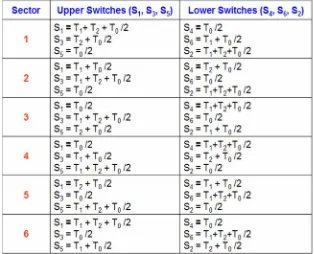
SVPWM refers to a special switching sequence of the upper three transistors of a three phase power inverter. There are two possible vectors called zero vector and active vector. the objective of space vector PWM technique is to approximate the reference voltage vector using eight switching patterns. One simple method of approximation is to generate average output of inverter in a small period, T to be the same as that of Vref in the same period.
SVM can be implemented by following steps:
A. Determination of Vd, Vq, Vref
2 2
q d ref
V
V
V
(11)B. Determination of T1, T2, T0
sin
3
cos
cos
3
sin
3
1
dc ref z
V
V
T
T
(12)
3
1
cos
.
sin
3
1
sin
.
cos
3
2
dc ref z
V
V
T
T
(13)
1 2
0
T
T
T
[image:5.612.170.484.480.734.2]T
Z
(14)Figure 4. Basic switching vectors and sectors
X. RESULTS
In this simulation we have considered a 33/11KV substation. We connected load of 100KVA for both transmission lines.
In this paper we have analyzed three cases they are
A. Effect on generation side due to heavy load on receiving side, in the absence of IPFC.
B. Effect on generation side due to heavy load on receiving side, in the presence of IPFC.
C. Effect of sudden increase in load on two transmission lines (both in presence & absence of IPFC).
[image:6.612.117.533.208.325.2]In all the three cases pulses are given to the 12 pulse converter by using space vector modulation (SVM) control technique. Voltage drop at the receiving end voltage of line 1 in the absence of IPFC
Figure.7 Voltage at Transmission line 1 in the absence of IPFC
From figure7 it is clear that there is a drop in receiving end voltage from 11KV to 5.6KV, which is due to heavy load on receiving end.
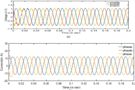
(a)
(b)
Figure 8(a) Voltage Waveform of Transmission line 1 in the presence of IPFC-SVM (b) Current Waveform of Transmission line 1 in the presence of IPFC-SVM
[image:6.612.81.525.368.665.2]D. Sudden Increase In Load On Transmission Line 1 And Transmission Line 2 Simultaneously
(a)
[image:7.612.68.535.87.342.2](b)
Figure.9 Voltage at Transmission line 1 and Transmission line 2 in the absence of IPFC
Figure 9 a &b represents the voltage at the end of both the transmission lines in the absence of IPFC and when a sudden load of 50KVA is added on the system at 0.1sec at the same time.it is observed that transmission voltage have been dropped from 4KVA to almost 2.8KVA when sudden load is added on the system.
(a)
(b)
Figure. 10(a) Voltage Waveform of Transmission line 1 and 2 in the presence of IPFC-SVM (b) Current Waveform of Transmission line 1 and 2in the presence of IPFC-SVM
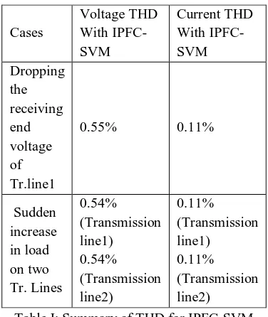
[image:7.612.72.534.415.669.2]Table I: Summary of THD for IPFC-SVM
XI. CONCLUSION
In this paper SVPWM controller for 12 pulse voltage source converter is proposed. The simulation results are analyzed using MATLAB 2017a software. Here we used PI control logic for three phase inverter proposed. Reduction of harmonics is better with the use of PI controller. It is useful in increasing DC bus utilization and reduction in THD values.
REFERENCES
[1] Povh D. Use of HVDC and FACTS. Proc. of the IEEE 2000; 88: 235-245.
[2] J. Guo, M. L. Crow and JagannathanSarangapani, “An Improved UPFC Control for Oscillation Damping”, Journal of IEEE Transactions on Power Systems,
Vol.24, No.1, pp.288-296, February 2009.
[3] Hingorani NG, Gyugyi L. Understanding FACTS: concepts and technology of flexible AC transmission systems. IEEEPress Marketing 2000: 2-16.
[4] Rosa N, Pires VF, Castro R. A New Model to Incorporate Unified Power Flow Controllers in Power Flow Studies. IEEE PES Transmission and Distribution
Conference and Exhibition 2006: 05TD0181.
[5] X. P. Zhang, “Modeling of the interline power flow controller and the generalized unified power flow controller in Newton power flow”,IEEE Proc.
Generation, Transmission and Distribution, vol. 150, No. 3,pp. 268-274, May 2003.
[6] Dr. Mary, D. and Ranjani, S. (March 2010) ‘Evaluation of Multiline FACTS Controller using Fuzzy Technology’, IE (I) Journal-EL Vol 90.
[7] Jianhong Chen. Vilathgamuwa, D.M. and Tjing T. Lie (2002) ‘Basic Control of Interline Power Flow Controller, IEEE Trans., 0-7803-73227/02.
[8] S.Devi, V.Suvitha, E.Mageswari, M.Yuvaleela, ―Simulation of Real and Reactive Power Coordination Using CSC Based IPFC for Power Quality Issues‖,
International Journal of Advanced Research in Electrical, Electronics and Instrumentation Engineering, ISSN (Online): 2278 – 8875 Vol. 3, Issue 11, and November 2014.
[9] Neha jain, ―IFTIPFC: an interactive functional toolkit related to Interline Power Flow Controller‖, IPASJ International Journal of Electrical Engineering
(IIJEE), ISSN 2321-600X, Volume 2, Issue 7, July 2014.
Cases
Voltage THD With IPFC-SVM
Current THD With IPFC-SVM Dropping
the receiving end voltage of Tr.line1
0.55% 0.11%
Sudden increase in load on two Tr. Lines
0.54% (Transmission line1)
0.54% (Transmission line2)
0.11% (Transmission line1)