Design of Efficient Binary Comparators using
Quantum-Dot Cellular Automata
Vikas Agrawal1, Shweta Agarwal2 1
Research scholar, 2Assistance Professor,RGPV Bhopal (M.P) Electronics and Comm. Dept., SRCEM Banmore, Morena, India
Abstract: In the era of technology development the reversible computation have reached the new level for better and efficient fabrication. The integration processes also become more changing job than the last decade. The new approach of QCA getting popular in the circuit designing. Due to this there is dramatically reduction in energy losses. The unique mapping of inputs and output helps to consumes less power. As well as the better performance is observed compare to the existing counterparts. In the presented algorithm the construction of reversible n-bit signed comparator circuit becomes more optimized. All the parameter of the comparator is improved. The proposed algorithm has achieved the enhanced result with more efficient with considering less area.
Keywords: Quantum-dot cellular automata, Computing, Signed Arithmetic, Low Power, Binary comparators, majority gates.
I. INTRODUCTION
In the present technology world every sort of computation is getting complicated. Due to this the researchers are in challenging situation to design the circuits which are formed by billions of transistors and execute the number of operation per second [1]. The count of transistor in the circuit become double in every two years and this process will continue till the semiconductor reaches its maximum physical limitations. In order to achieve higher speed of computation various kinds of computing technology such as QCA Processing [2], DNA Computing [3], microprocessor [4-5] etc. But the current architecture is getting huge power losses due to dissipation. By the effort of Landauer [6] the calculation of every bit of information dissipated the minimum KT × ln2 joules of energy here K is the Boltzamann's constant and T is the absolute temperature at which the operation is being performed. Bennet had proposed the work according to which the issue of dissipation of energy in VLSI circuits can be overcome by using QCA logic. By this the information is maintained as it was without losing a single bit. Reversible logic allows performing Boolean operations having same number of inputs and outputs where input combinations are uniquely mapped to individual output combinations [7]. Reversible logic does not permit feedbacks. Reversible logic can perform multiple operations per cycle without compromising in input bits. In order to get zero power dissipation QCA technology is employed [8].
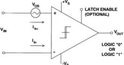
In the comparator two inputs are available, in which first input is set point and other is used to provide the user-adjustable, depending on the design. In Figure 1 the basic comparator is given. The uncertain input voltage, such as a speed of vehicle, is continually compared to the setpoint; if the input is more than the setpoint, the output terminal provide high; if the input is less than the input, the output terminal provide low.
[image:1.612.207.409.542.649.2]Fig 1: A comparator implements a simple and very nonlinear transfer function:
Fig. 2 Block Diagram of Comparator.
II. FUNDAMENTALS OF QCA
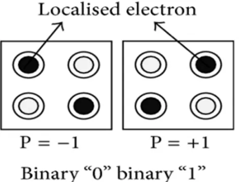
[image:2.612.183.433.317.459.2]In the QCA the information is stored and transports the data by just changing local position. There is no actual transport of any charge carrier from unit to another unit. As in case of electrical system the storage is only possible by continue rotation of value. The two charges binary 1 and binary 0 can be represented by arrangement of quantum dots [9-11]. There are only two quantum dots are presented in the QCA cell. The orientation of quantum dots is altering by the coulombic interaction between them. In the figure 3 structure of QCA is shown. It works as the smallest block of the QCA. The QCA cell has four dots at all its corner [12]. In the structure there are two free electrons. The structure of the QCA in provided in the figure 4.
Fig. 3 Structure of a QCA Cell
Because of the coulombic force of repulsion the two electrons can be in two stable states [13]. The electrons are always presented in diagonally opposite corners of the QCA cell. The diagonally opposite corners have maximum distance. The stable states are called as polarization. As per the locations of the electrons in the cell two states can be take place [14]. These states are considered as binary states 1 and 0. For the purpose of explanation the figure 2 is shown.
[image:2.612.193.428.530.709.2]The diagonally opposite electrons interact to each other by the electrostatic forces and due to this force the electrons maintain its polarization [15].
The input cell is driving the other cells. If logic 1 is provided as input then other cell due to colomibic effect get the logic 1. Similarly if logic 0 is provided other cell gets logic 0. The data can be transfer and propagate in a path consisting of the cell automata [16-17]. Figure 1 shows the available two cell types.
There are two logics gates which are using in QCA technology are the inverter and the majority gate (MG) [18]. In the available MG gate there are three inputs a, b, and c. These are responsible for logic operations. All the operations are associated with clock. The different blocks are controlled by the same clock. Let clock be named as clk x, whereas the remaining cells of the MG are associated with the clock signal clk x+1.
M (a, b, c) = a·b + a·c + b·c. (1)
The 1-digit BCD adder earlier proposed in use the top-level architecture in Fig. 3. In this the inputs are added in the binary format and then perform the conversion of BCD. If the output is greater than the 9 than 6 is added in it, else the addition of 0 is take place [19].
III. PROPOSED COMPARATOR USING QCA IMPLEMENTATIONS
The proposedwork has the two theorems and corollaries. This proposed concept is helpful for enhancing the speed and performance of the full comparators. By using this theorem the number of LUTs reduces so that the size of the overall device is reduced. As the QCA having majority gate and inverter are basic building block [20]. The following theorems are presented in such a manner that the full comparators are splitting into A(n−1:0)=an−1...a0 and B(n−1:0)=bn−1...b0 operands. It can be done by comparing as well as applying Theorems 1 and 2.
1) Theorem 1: If A(k−1:k−2)=ak−1ak−2 and B(k−1:k−2)= bk−1bk−2, with k=2, 4,..., n–2,n, are two 2-bit sub words of then-bit numbers A(n−1:0)and B(n−1:0), respectively, then A big B(k−1:k−2) as defined in (2) is equal to 1 if and only if A(k−1:k−2)>B(k−1:k−2);B big A(k−1:k−2)as defined in (3) is equal to 0 if and only if A(k−1:k−2) < B(k−1:k−2) .
IV. DESIGNING BINARY COMPARATORS EXPLOITING THE NEW THEOREMS
The proposed work is shown in figure 5 in form of circuit. The circuits illustrated the design to implement in QCA the novel equations demonstrated. The overall design is shown as generic module. Here the inputs are A and B. The output gives the comparative values in form of greater than, equal to and less than. The Ti, with I ranging between 1 and 4, implements the equations enunciated in the ith theorem, whereas C1 and C2 compute the signals AbigB(k−1:0), BbigA(k−1:0), and A eqB(k−1:0)as shown in figurer 5. The application of this comparator can be observed in cascade-based and TB architectures. However, many other design can be developed by combining the basic modules in different manners. Cascade – based (CB) architecture is firstly proposed using novel QCA technology. For better understanding the figure 5 has explain with different angle of observation [9].By using these theories the implementation of 16 bit of comparator is designed.
In figure 5 the criterion are explained. C1 and C2 of Figure 5 provide the circuit implementation of criterion. The n-bit cascade based architecture of full comparator design is proposed here it uses: n/3 instances of T1 and T2 n/3 cascaded instances of T4 through which the signals AbigB(n−1:0) and BbigA(n−1:0) are computed; and C2 is used for computing AeqB(n−1:0). The circles design shown in figure 5 indicates the additional clock phases that have to be inserted on wires to guarantee the correct synchronization of the overall design [10].
Fig. 5. QCA modules: (a) T1; (b) T2; (c) T3; (d) T4; (e) C1; and (f) C2
Table 1 – Splitting Criterion adopted in the CB comparators
N Splitting of the Operands
4 A(3:2)A(1:0) B(3:2)B(1:0)
8 A(7:5)A(4:2)A(1:0) B(7:5)B(4:2) B(1:0)
16 A(15:14)A(13:11)A(10:8) A(7:5)A(4:2) A(1:0)
B(15:14)B(13:11)B(10:8) B(7:5)B(4:2) B(1:0)
V. RESULT
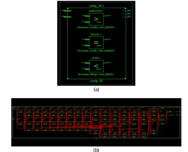
After apply such innovative comparator we got the following result. The delay is reduced. The comparator is having very much efficient then the exiting comparator. The result is shown in figure 6 is the RTL designing. This designed is provided by which the implantation is shown.
(a)
(b)
[image:5.612.111.492.410.717.2]In the figure 6 (b) the internal schematic views is shown. Here the buffer, multiplexer and other component are given which are arranged in the different combination. The wires are used to connect the parts.
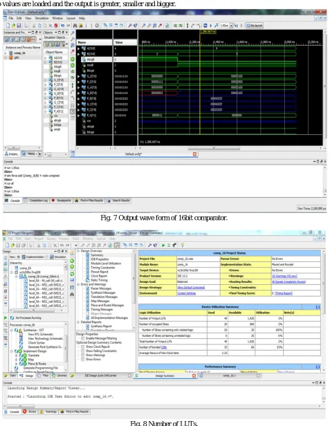
[image:6.612.69.546.117.733.2]In fig. 5 the wave form of the comparator is given. The different values as has been applied to test the working of the device. Here the two values are loaded and the output is greater, smaller and bigger.
[image:6.612.70.542.437.721.2]Fig. 7 Output wave form of 16bit comparator.
VI. CONCLUSION
This paper presents a systematic approach to design an n-bit signed comparator. The comparator which is designed is capable to work with high end devices. It can work by integrate in any device as it is very much efficient to perform the required operations. By examining the efficiency in different parameters it is found that presented comparator is efficient than other presented area. The key feature of this technology is that the QCA is very easy to implement and work effectively. Able to work under Quantum cost minimization is the strength of the proposed architecture. Since comparison of two numbers can be useful in many operations inside the microcontroller, system of communication, etc.
REFERENCES
[1] Moore, Gordon E, (1975) “Progress in digital integrated electronics”, Electron Devices Meeting, Vol. 21(1975), IEEE 11-13.
[2] Steane, Andrew, Feb(1998) “Quantum computing”, Reports on Progress in Physics, Vol. 61. No. 2, pp117-173.DOI: http://dx.doi.org/10.1088/0034-4885/61/2/002
[3] Paun, Gheorghe, Grzegorz Rozenberg, and Arto Salomaa, (1998) “DNA computing: new computing paradigms”, Springer-Verlag New York Inc. Secaucus,NJ. USA(1998), ISBN:3540641963.
[4] B. Sinharoy et al., “IBM POWER8 processor core microarchitecture,” IBM J. Res. Dev., vol. 59, no. 1, pp. 1–21, Jan./Feb. 2015. [5] L. Eisen et al., “IBM POWER6 accelerators: VMX and DFU,” IBM J.Res. Dev., vol. 51, no. 6, pp. 1–21, Nov. 2007.
[6] Rolf Landauer, (1961) “Irreversibility and heat generation in the computing process”, IBM journal of research and development, Vol. 44. No. 1(1961), pp261-269.DOI: http://dx.doi.org/10.1147/rd.441.0261
[7] Patel, Ketan N., John P. Hayes, and Igor L. Markov, (2004)“Fault testing for reversible circuits",Computer-Aided Design of Integrated Circuits and Systems, IEEE Transactions, Vol. 23. No. 8 (2004),pp1220-1230.
[8] Tommaso Toffoli, (1980) “ Reversible computing”, MIT Lab for Computer Science. Seventh Colloquium Noordwijkerhout, The Netherlands. Vol. 85.Jul(1980), pp632–644. DOI: http://dx.doi.org/10.1007/3-540-10003-2_104
[9] Morita, Kenichi, (2001) “A simple universal logic element and cellular automata for reversible computing”, Machines, Computations, and Universality, Springer Berlin Heidelberg, 2001, pp102-113.
[10] Voyiatzis, Ioannis, Dimitris Gizopoulos, and Antonis Paschalis, (2005)“Accumulator-based test generation for robust sequential fault testing in DSP cores in near-optimal time”,Very Large Scale Integration (VLSI) Systems, IEEE Transactions, Vol 13.No. 9 (2005),pp1079-1086.
[11] Snider, G. L., et al,(1999) “Quantum-dot cellular automata: Review and recent experiments”,Journal of Applied Physics, Vol. 85.No. 8 (1999),pp4283-4285. [12] WALUS, Konrad, et al, (2004)“QCA Designer: A rapid design and simulation tool for quantum-dot cellular automata”, IEEE transactions on nanotechnology,
Vol. 3.No. 1 (2004), pp26-31.
[13] S.P.Singh and S.Agrawal (2018), “ Design of Efficient 32bits of BCD adder in QCA”, International journal for research in applied science & engineering technology, Vol 6 Issue II (2018).
[14] Naresh and P.Ashok (2016), “Implementation of QCA Comparator Arch. for Power Critical Applications”, IJITR, Vol. no 4, Issue No. 5.
[15] R.Nithiyanandham, et al, “Adder Design Using QCA Technique with Area Delay Efficient”, International Journal of Innovation Research in Science, Engg. And Tech.
[16] H. Cho and E. E. Swartzlander Jr., “Serial parallel multiplier design in quantum-dot cellular automata,” inProc. IEEE Symp. Comput. Arithmetic, 2007, pp. 7– 15.
[17] T.Rajeswari and V.P.Reddy, “Design of Efficient Binary Comparators In QCA”, International Journal of Research.
[18] G. Cocorullo, P. Corsonello, F. Frustaci, and S. Perri, “Design of Efficient BCD Adders in Quantum-Dot Cellular Automata”,IEEE Transactions On Circuits And Systems—Ii: Express Briefs, Vol. 64, No. 5, May 2017.
[19] V. Pudi and K. Sridharan, “Low complexity design of ripple carry and Brent-Kung adders in QCA,”IEEE Trans. Nanotechnol., vol. 11, no. 1,pp. 105–119,Jan. 2012.