Optimization of Double Pipe Eccentric Heat
Exchanger using Taguchi Method and CFD
Modeling
Bhanvendra Singh1, Hari Mohan Sharma2
1
M.Tech Student, 2Assistant Prof. Apex Institute of Engineering and Technology, Jaipur
Abstract: In present research work a double pipe heat exchanger is selected for CFD based simulation work using design of experiment (DOE) technique called “taguchi method”. Total experiments are set for 32 run using mixed taguchi method. Total five factors are selected which are type of insert, type of tube, type of fluid, temperature of cold fluid and mass flow rate having four levels each. One response is generated for this which is effectiveness. The results are set as per stat tools and specially signal to noise ratio analysis and ANOVA analysis. CD based optimization is used to find optimization results for effectiveness. Keywords: double pipe heat exchanger, CFD simulation, DOE, taguchi method, CD function optimization
I. INTRODUCTION
Heat exchanger is mechanical equipment which is used to transfer thermal energy between two or more fluid, between fluid and solid surface (Practical), at different temperature in thermally contact. It does not required any external heat and work interaction. The purpose of constructing a heat exchanger is to get an efficient method of heat transfer from one fluid to another, by direct contact or by indirect contact. It is using in various practical application filed such as heating and cooling of fluids, space heating, refrigeration, air conditioning, power stations, chemical plant, petroleum refinery, sewage treatment etc. Some common heat exchangers are shell and tube, condensers, evaporator, automobile radiator, cooling tower and air-pre heater. In heat exchanger, tube is important role play to transfer energy therefore many research works is carried out to improved heat exchanger tube by using heat enhancement techniques.
The heat transfer occurs by three manners: conduction, convection and radiation. In a heat exchanger, the heat transfer through radiation is not taken into account as it is negligible in comparison to conduction and convection. Conduction takes place when the heat from the high temperature fluid flows through the surrounding solid wall.
II. AIM OF RESEARCH
The aim of research study is to develop a customized tube and tube heat exchanger which work on different fluid flow conditions. The warm fluid will be collected using solar water heater or other alternative energy sources, so this heat exchanger is work on renewable energy concept also. Every research is based on DOE methodologies, so in this current research work, taguchi Method and optimization technique will be used for more advanced results. Total 32 experiments cases will be designed for this research work. Advanced numerical simulation work will also conduct in this research work using commercial CFD software Ansys Fluent. Optimization of model equation developed for this research work will optimize using MATLAB software by using ANN/MOGA/Fuzzy Logic technique. Some important parameters which will be selected for research work are following: like mass flow rate of fluid, heat transfer, design variable of heat exchanger, material type of HE device and Installation of HE as per flow conditions, which will finalized after literature review of research work and local market survey.
III. CFD MODELING STEPS
Experimental and simulation both studies are investigated for one fluid having cold and hot fluid condition flow heat exchanger All important steps are present in following section.
A. Step I: Formulation of flow Problem
Tube without insert Tube with insert
Fig.1 CFD Flow Problem
B. Step II: Making of Flow Domain
ETHE is to be analyzed using CFD simulation, so geometrical modeling of this body is required for CFD simulation. This CAD modeling is generally done by using CAD software. This task is completed by using Ansys DM software. Some assumption or approximations on geometry are selected by researchers for this step like mechanical joints available in experimental setup, some unwanted curvature etc. It is common assumption take care in CFD modeling steps. Grid generation is highly dependent on this step so require expertise knowledge in CAD modeling of CFD domain.
Fig.2 CFD Domain CAD diagram
C. Step III: Formulation of Boundary Conditions
Fig.3 Boundary of ETHE (a) inflow BC (b) outflow BC
D. Step IV: Grid Generation
Flow domain of ETHE is required to discretize into grids to solve fluid governing equations using Ansys Fluent software. This task is completed using Ansys ICEM CFD grid generation software. Finite structured grids are generated using this software.
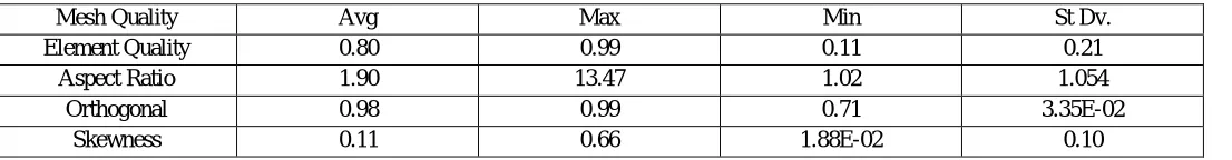
TABLE 1
Grid Quality Index For Discretized Domain Of Ethe
Mesh Quality Avg Max Min St Dv.
Element Quality 0.80 0.99 0.11 0.21
Aspect Ratio 1.90 13.47 1.02 1.054
Orthogonal 0.98 0.99 0.71 3.35E-02
Skewness 0.11 0.66 1.88E-02 0.10
E. Step V: Establish CFD simulation
[image:2.612.37.590.595.667.2]Fig.4 GUI of Ansys Fluent software
F. Step VI: Set Solution Controls
After selection of proper selection of data inputs time to select proper solution techniques to solve governing equations. This step is solved using Ansys Fluent software.
G. Step VII: Monitor Simulation parameters (Residuals)
H. Step VIII: Post Processing of Simulation
[image:4.612.191.424.125.241.2]In this step required results are extracting from solved files of Ansys Fluent software. The main results extracted from CFD simulation are contours
Fig.6 Contours for ETHE (Temperature)
1) Factor And Levels
TABLE 2
Process Parameters And Their Levels
Factor Parameter Unit Level
L1 L2 L3 L4
A TOI - 1 2 - -
B PD - 1 2 3 4
C FT - 1 2 3 4
D C-MFR L.min 1.0 1.5 2.0 2.5
E COLD-TEMP K 290 295 300 305
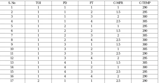
2) Orthogonal Array
TABLE 3
L32 Oa For Present Research Work
S. No TOI PD FT C-MFR C-TEMP
1 1 1 1 1 290
2 1 1 2 1.5 295
3 1 1 3 2 300
4 1 1 4 2.5 305
5 1 2 1 1 295
6 1 2 2 1.5 290
7 1 2 3 2 305
8 1 2 4 2.5 300
9 1 3 1 1.5 300
10 1 3 2 1 305
11 1 3 3 2.5 290
12 1 3 4 2 295
13 1 4 1 1.5 305
14 1 4 2 1 300
15 1 4 3 2.5 295
16 1 4 4 2 290
[image:4.612.45.576.453.731.2]S. No TOI PD FT C-MFR C-TEMP
18 2 1 2 2 295
19 2 1 3 1.5 300
20 2 1 4 1 305
21 2 2 1 2.5 295
22 2 2 2 2 290
23 2 2 3 1.5 305
24 2 2 4 1 300
25 2 3 1 2 300
26 2 3 2 2.5 305
27 2 3 3 1 290
28 2 3 4 1.5 295
29 2 4 1 2 305
30 2 4 2 2.5 300
31 2 4 3 1 295
32 2 4 4 1.5 290
IV. RESULT AND DISCUSSION
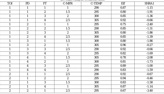
A. Effect Of Signal To Noise (S/N) Ratio On Effectiveness
[image:5.612.35.577.427.738.2]S/N ratio analysis for effectiveness is performed using “larger is better” option and results are present in table 5.3. These individual S.N ratio results are used for rank identification and optimal solution for effectiveness
TABLE 4
S/N Ratio Analysis Of Effectiveness
TOI PD FT C-MFR C-TEMP Eff SNRA1
1 1 1 1 290 0.87 -1.15
1 1 2 1.5 295 0.80 -1.91
1 1 3 2 300 0.85 -1.36
1 1 4 2.5 305 0.92 -0.66
1 2 1 1 295 0.75 -2.40
1 2 2 1.5 290 0.85 -1.31
1 2 3 2 305 0.80 -1.86
1 2 4 2.5 300 0.85 -1.39
1 3 1 1.5 300 0.80 -1.86
1 3 2 1 305 0.96 -0.27
1 3 3 2.5 290 0.92 -0.66
1 3 4 2 295 0.82 -1.69
1 4 1 1.5 305 0.78 -2.08
1 4 2 1 300 0.81 -1.73
1 4 3 2.5 295 0.89 -1.00
1 4 4 2 290 0.83 -1.59
2 1 1 2.5 290 0.92 -0.67
2 1 2 2 295 0.94 -0.46
2 1 3 1.5 300 0.83 -1.58
TOI PD FT C-MFR C-TEMP Eff SNRA1
2 2 2 2 290 0.86 -1.23
2 2 3 1.5 305 0.65 -3.63
2 2 4 1 300 0.64 -3.84
2 3 1 2 300 0.69 -3.10
2 3 2 2.5 305 0.93 -0.58
2 3 3 1 290 0.90 -0.84
2 3 4 1.5 295 0.84 -1.43
2 4 1 2 305 0.80 -1.90
2 4 2 2.5 300 0.89 -0.96
2 4 3 1 295 0.74 -2.56
[image:6.612.35.577.68.562.2]2 4 4 1.5 290 0.78 -2.08
Fig.7 Full matrix of interaction plots for Effectiveness
B. Optimal Solution for Effectiveness
TABLE 5
Rank Identification Of Effectiveness (Raw Data)
Level TOI PD FT C-MFR C-TEMP
1 0.84 0.88 0.79 0.82 0.87
2 0.81 0.76 0.88 0.79 0.81
3 0.86 0.82 0.82 0.80
4 0.81 0.82 0.87 0.84
Delta 0.03 0.11 0.09 0.08 0.07
Rank 5 1 2 3 4
0.9 0.8 0.7 305 300 295 290 4 3 2
1 1.0 1.5 2.0 2.5
0.9 0.8 0.7 0.9 0.8 0.7 0.9 0.8 0.7 2 1 0.9 0.8 0.7 4 3 2 1 TOI PD FT C-MFR C-TEMP 1 2 TOI 1 2 3 4 PD 1 2 3 4 F T 1.0 1.5 2.0 2.5 C-MFR 290 295 300 305 C-TEMP
Interaction Plot for Eff
[image:6.612.39.580.621.721.2]TABLE 6
Rank Of Each Factor For Each Response Variable
Response A B C D E
Eff. 5 1 2 3 4
TABLE 7
MULTI RESPONSE FOR ALL RESPONSES
Solution A B C D E Effectiveness CD
1 1 1 4 2.5 290 1.1332 0.729783
V. CONCLUSION
Double pipe heat exchanger is used in this research work. The work is completed using CFD modeling technique. Design of experiment method called “Taguchi method” and the main conclusion is present here:
A. Signal to noise ratio analysis is performed for effectiveness and the best factor pipe design and least factor is type of design
B. Interaction plots are generated for effectiveness to show the relation among any two factors.
C. CD function based optimization is also performed and the results are present in previous section of this research work.
REFERENCES
[1] Miss Sneha.H.Dhoria, Mr E. Manoj Kumar, I.V.S.Yeswanth3, Miss Lakshmi Jayanti ISSN: 2248- 9622, Vol. 8, Issue 6 (Part -II) June 2018, [2] Byung-Hee Chun, Hyun Uk Kang, and Sung Hyun Kim Korean Journal of Chemical Engineering September 2008, Volume 25,Issue5,pp 966–971 [3] SamiD.Salman, AbdulAmirH. Kadhum, MohdS.Takriff, and AbuBakarMohamad Hindawi Publishing Corporation, Mathematical Problemsin
Engineering.Volume2013.
[4] Praveen Kumar Kanti, Karthika.U.P, Sabeer Ali, SanathKumar.N, ShyamChandran C “CFD analysis of shell and tube heat exchanger”, ISSN: 2319-6890)(online), 2347-5013(print) Volume No.5 Issue: Special 6, pp: 1129 -1254, 20 May 2016.
[5] Jibin Johnson, Abdul Anzar V M, Abith Shani, Harif Rahiman P, Hashmi Hameed T S, Nithin V S International Journal of Science, E ngineering and Technology Research (IJSETR), Volume 4, Issue 5, May 2015.
[6] D.Bhanuchandrarao, M.Ashokchakravarthy, Dr. Y. Krishna, Dr. V .V. SubbaRao, T.Hari Krishna “CFD Analysis And Performance Of Parallel And Counter Flow In Concentric Tube Heat Exchangers”, ISSN: 22780181,Vol. 2 Issue 11, November – 2013.
[7] S.D.Salman, A.H. Kadhum, M.S.Takriff, and A. Mohamad B.,“CFD simulation of heat transfer and friction factor augmentation in a circular tube fitted with elliptic-cut twisted tape inserts,” Mathematical Problems in Engineering, vol. 2013, ArticleID163839,7pages,2013.
[8] Bharat Bhushan Verma, Saurabh Kumar IOSR Journal of Mechanical and Civil Engineering (IOSR-JMCE) e-ISSN: 2278-1684,p-ISSN: 2320-334X, Volume 13, Issue 3 Ver. VII (May- Jun. 2016).