Object Manipulation Using
Cooperative Mobile Multi-Robot Systems
Ignacio Mas and Christopher Kitts
Abstract—Transportation of large objects or their manipula-tion in hazardous environments are tasks where the utilizamanipula-tion of groups of mobile robots working in a cooperative fashion can be of great advantage. To execute such tasks, a multi-robot formation control framework is necessary in order to coordinate the motions of the robots in the group. In this article, a particular formation control approach called cluster space control is utilized to control a group of four non-holonomic wheeled robots. A single operator using a joystick input controls in run time the position of all the robots in the formation. We first present the application of the cluster space framework to a group of four robots and show how it is used in a closed loop controller that facilitates a pilot to appropriately control all the degrees of freedom of the formation. Then, the tasks of cooperatively manipulating and transporting an object are implemented and verified using a hardware experimental testbed.
Index Terms—multi-robot, robot cooperation, object trans-portation, cluster space control, mobile robots.
I. INTRODUCTION
S
YSTEMS of multiple robots have the potential to im-prove application-specific performance by offering re-dundancy, increased coverage and throughput, flexible recon-figuration, or spatially diverse functionality [1]. For mobile systems, a driving consideration is the method by which the motions of the individual vehicles are coordinated. Central-ized control approaches have been successfully demonstrated [2] and have been found to be useful for material transport, regional synoptic sampling, and sensing techniques where ac-tive stimulus and/or signal reception are spatially distributed [3], [4], [5]. Such approaches, however, typically suffer from limited scalability and the need for global information. As an alternative, developments in decentralized approaches have been shown to hold great promise in addressing scalability and limited information exchange [6], [7]; such approaches often employ control strategies that are behavioral [8], [9], biologically inspired [10], optimization-based [11], or poten-tial field-based [12], [13], [14], [15].Large object transportation and manipulation of objects in hazardous environments are tasks that can benefit from the utilization of groups of mobile robots working in a coop-erative fashion. The group surrounds or entraps the object of interest and then transports it to a desired destination by applying pushing forces upon it [16]. A multi-robot
Manuscript received July 06, 2012; revised August 10, 2012. This work has been sponsored through a variety of funding sources to include Santa Clara University Technology Steering Committee grant TSC131 and National Science Foundation Grant No. CNS-0619940.
I. Mas is with the National Scientific and Technical Research Coun-cil (CONICET) and the Center for Systems and Control (CeSyC), Buenos Aires Institute of Technology (ITBA), Buenos Aires, Argentina.
C. Kitts is with the Robotic Systems Lab, Santa Clara University, Santa Clara, CA 95053, [email protected]
formation control framework is necessary to coordinate the motions of the robots in the group.
Reports in the literature regarding multi-robot transporta-tion of objects show different techniques implementing this task, using approaches from behavioral-based methods [17] to lead-follower techniques [18] or potential field-based entrapments [19], [20], [21], [22].
In this article, a particular formation control approach called cluster space control framework [23] is utilized to control a group of four non-holonomic wheeled robots. A single operator using a joystick input controls in run time the position of all the robots in the formation. This is made possible by the level of abstraction introduced by the control framework, which allows for specification, control and mon-itoring of formation parameters such as position, orientation and shape of the group, instead of those positions of the individual members. In this work, we first apply the cluster space control methodology to a group of four robots, defining an appropriate set of formation parameters that represent the system, and show how they are implemented in a closed loop controller that allows a pilot to control all the degrees of freedom (DOF) of the formation in a simplified fashion. Then, cooperative object manipulation and transportation tasks are verified using a hardware experimental testbed.
A discussion of the results reveals the advantages of using the cluster space control framework to conduct this task, showing that only one pilot is required to perform the complex simultaneous motions of four non-holonomic mobile robots.
We have successfully used the cluster space control ap-proach in experiments with surface vessel systems [24] and aerial blimps [25], for robots that are both holonomic and non-holonomic, for robots negotiating obstacle fields [26], and for target applications such as escorting and patrolling [27]. Preliminary simulation results applying this technique to object manipulation were presented in [28].
II. CONTROLAPPROACH
The cluster space approach to controlling formations of multiple robots was first introduced in [23]. The first step in the implementation of the cluster space control architecture is the selection of an appropriate set of cluster space state variables. To do this, we introduce a cluster reference frame and select a set of state variables that capture key pose and geometric elements of the cluster.
Fig. 1. Reference frame and cluster space variables definition for a four-robot planar system
articulated. This leads to the use of several general categories of cluster pose variables (and their derivatives) that specify cluster position, cluster orientation, relative robot-to-cluster orientation, and cluster shape. A general methodology for selecting the number of variables corresponding to each category given the number of robots and their DOF is described in [23]. Furthermore, an appropriate selection of cluster variables allows for centralized or distributed control architectures [29].
For a planar four-rover system, the robot space pose is defined as:
r= (x1,y1,θ1,x2,y2,θ2,x3,y3,θ3,x4,y4,θ4) T
, (1)
where(xi,yi,θi)
T defines the position and orientation of robot
i. The cluster space variables are defined as:
c= (xc,yc,θc,φ1,φ2,φ3,φ4,o´,p,q,s,β) T
. (2)
Figure 1 depicts the relevant reference frames for the planar four-robot problem indicating the definitions of the cluster space variables. These variables describe the cluster position (xc,yc), orientation (θc), and shape ( ´o,p,q,s,β), as
well as the relative orientation of the robots with respect to the orientation of the cluster (φi). It should be noted that the resulting space definition conserves the 12 DOF–equivalent to the original system of four 3-DOF robots–therefore, the resulting system is fully articulated and any pose can be attained.
We wish to specify multi-robot system motion and com-pute required control actions in the cluster space using the cluster state variables selected. Given that these control actions will be implemented by each individual robot (and ultimately by the actuators within each robot), we develop formal kinematic relationships relating the cluster space variables and robot space variables.
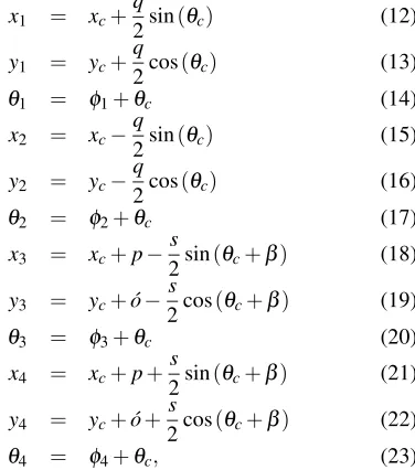
Given the aforementioned selection of cluster space state variables, we can express the cluster forward and inverse position kinematics of the four-robot system. The forward position kinematics are given by:
q = (x1−x2)2+ (y1−y2)2 (9)
s =
q
(x3−x4)2+ (y3−y4)2 (10) β = atan2(x4−x3,y4−y3)
−atan2(x1−x2,y1−y2), (11)
where atan2(y,x) is the 4-quadrant arctangent [30]. The
inverse position kinematics are therefore defined by:
x1 = xc+
q
2sin(θc) (12)
y1 = yc+
q
2cos(θc) (13)
θ1 = φ1+θc (14)
x2 = xc−
q
2sin(θc) (15)
y2 = yc−
q
2cos(θc) (16)
θ2 = φ2+θc (17)
x3 = xc+p−
s
2sin(θc+β) (18) y3 = yc+o´−
s
2cos(θc+β) (19)
θ3 = φ3+θc (20)
x4 = xc+p+
s
2sin(θc+β) (21) y4 = yc+o´+
s
2cos(θc+β) (22)
θ4 = φ4+θc, (23)
We may also consider the formal relationship between the robot and cluster space velocities, ˙rand ˙c. By differentiating the forward and inverse position kinematics, the forward and inverse velocity kinematics can easily be derived, obtaining the cluster Jacobian and Inverse Jacobian matrices,J(r)and J−1(c)that verify ˙c=J(r)r˙and ˙r=J−1(c)c˙.
The particular selection of cluster space variables is not unique, and different sets of variables may be chosen fol-lowing the same methodology when more convenient for a given task.
[image:2.595.345.551.68.257.2]III. CONTROLARCHITECTURE
[image:2.595.360.548.293.506.2]Fig. 2. Cluster Space Control Architecture. Desired positions and velocities are input by the pilot through a joystick interface. Control actions are computed in the cluster space and converted to the robot space through the use of the inverse Jacobian relationship. Robot sensor information is converted back to cluster space through the forward kinematics and Jacobian matrix to close the loop.
[image:3.595.61.278.362.531.2]The non-holonomic constraints given by the unicycle-like differential-drive motion of the robots effectively reduce the number of independently specified cluster pose variables to eight. As a consequence, inner-loop robot-level heading control is implemented on each robot and the cluster space controller does not regulate the four cluster parameters corresponding to yaw orientation of the robots relative to the cluster, specificallyφi.
Fig. 3. Boe-Bot robots retrofitted with wireless communication units and vision-based tracking system tags.
IV. EXPERIMENTS
To verify the functionality of the method, a testbed con-sisting of four non-holonomic mobile robots is utilized to perform object transportation tasks. The robots used are Boe-Bots, off-the-shelf miniature rovers from Parallax Inc. The rovers are differentially-driven and carry Parallax BA-SIC Stamp microprocessors. These commercial units were retrofitted with X-Bee RF communication modules from Digi International Inc. Robot position and orientation were sensed using the OptiTrack Vision system from NaturalPoint Inc. The Vision-based tracking system relays position information to a central computer running a Matlab implementation of the cluster space controller. The resulting sensing accuracy is under 1cm and the controller servo rate is 10Hz. Desired cluster position and orientation are input by the operator with a joystick and compensation commands are sent wirelessly to
the robots for actuation. Figure 3 shows the Boe-Bot mobile robots in their test configuration.
Figure 4 shows screen shots of an object transportation task performed with four robots controlled by a single operator. The robots come into contact with the square object, and the cluster follows a U-shaped trajectory specified by the operator in real-time using a joystick.
Desired and measured values of the cluster parameters over time are shown in Figure 5. For simplicity, only relevant variables for the particular task are represented, specifically, position (xc,yc), orientation (θc) and two shape variables
(q,s). It can be seen how the operator changes the desiredx
andyposition of the formation and the controller generates compensation commands that produce trajectory tracking. The delay between desired and measured values is due to the non-holonomic nature of the robots and their velocity limitations. When the formation changes its direction of motion, the heading control takes some time to change the bearings of the individual robots to move forward in a different direction.
The position of the object during the experiment is shown from an overhead view in Figure 6, together with the com-manded cluster position that produces the object trajectory.
A different experiment is shown in Figure 7 where the formation changes the object’s orientation. The robots sur-round the object and a cluster orientation trajectory produces a torque on the object. This trajectory is easily specified by the operator by varying the cluster orientation parameter,θc, which results in complex motions of the individual robots.
Figure 8 shows the desired and measured values of the relevant cluster space parameters over time. After an initial transient, the formation attains the desired position and shape, and the orientation variable follows a trajectory input by the operator in real-time through a joystick. At the end of the task, the size parameters (q and s) are increased for the formation to release the object.
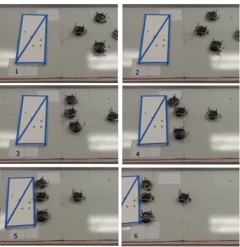
In the last experiment, a rectangular object is transported. To evenly apply pushing forces, the formation shape variable
´
Fig. 4. Experimental results of the transportation of a large object using a 4-robot cluster. The robots entrap the object and push it following a U-shaped trajectory. The video of the experiment can be found at http://youtu.be/4eDFdNmscAg
V. DISCUSSION
Applying cluster space control to object transportation and manipulation tasks has some advantages and shortcomings compared to other methods found in the literature. For example, our proposed method allows for the robots to simultaneously move in the workspace, with no need to take turns to perform discrete actions as in [17]. In contrast to lead-follower methods [18], [31] , our approach allows for a higher level of abstraction in the definition of the group. Consequently, specifying motions like ‘rotate formation’ or ‘increase formation size’ can be achieved through a smaller number of control variables. As a drawback, a higher level of communication is needed and robustness to robot failure decreases. Compared to potential field-based approaches [19], cluster space control does not needa prioriknowledge of the shape of the object to be transported, a requirement to create a suitable potential function. The operator can modify the shape and orientation of the formation in run time to perform the task.
Finally, different sets of cluster space variables can be defined for a given formation. The operator can benefit from a particular selection of variables that responds to the control needs of the task. In the example presented in this article, the selection of the centroid of the robots as the cluster position simplifies the task of surrounding the object, as the position of the cluster and that of the object coincide, and the rotation task is performed by changing the orientation of the formation around the centroid.
[image:4.595.303.544.52.310.2]Fig. 5. Time history of the relevant cluster space variables for the transportation of a large object shown in Fig 4. The position of the formation follows the input trajectory set by the user and the orientation and shape variables stay regulated.
Fig. 6. Overhead plot of the position of the object and the commanded position of the cluster centroid for the transportation of a large object shown in Fig 4. The position of the box follows the input trajectory set by the user.
VI. CONCLUSION
[image:4.595.322.531.370.568.2]Fig. 7. Experimental results of the rotation of a large object using a 4-robot cluster. The robots entrap the object and change its orientation. The video of the experiment can be found at http://youtu.be/4eDFdNmscAg
ACKNOWLEDGMENT
The authors gratefully thank Steve Li for his help de-veloping and maintaining the experimental testbed used in this publication and Mike Rasay for improving the robot bumper systems. Any opinions, findings, and conclusions or recommendations expressed in this material are those of the authors and do not necessarily reflect the views of the National Science Foundation.
REFERENCES
[1] C. Kitts and M. Egerstedt, “Design, control, and applications of real-world multirobot systems [from the guest editors],”Robotics & Automation Magazine, IEEE, vol. 15, no. 1, pp. 8–8, March 2008. [2] K.-H. Tan and M. Lewis, “Virtual structures for high-precision
coop-erative mobile robotic control,”Intelligent Robots and Systems, IROS, Proceedings of the IEEE/RSJ International Conference on, vol. 1, pp. 132–139, Nov 1996.
[3] M. Hashimoto, F. Oba, and T. Eguchi, “Dynamic control approach for motion coordination of multiple wheeled mobile robots transporting a single object,” Intelligent Robots and Systems ’93, IROS ’93. Proceedings of the 1993 IEEE/RSJ International Conference on, vol. 3, pp. 1944–1951 vol.3, Jul 1993.
[4] D. Rus, B. Donald, and J. Jennings, “Moving furniture with teams of autonomous robots,”Intelligent Robots and Systems 95. ’Human Robot Interaction and Cooperative Robots’, Proceedings. 1995 IEEE/RSJ International Conference on, vol. 1, pp. 235–242 vol.1, Aug 1995. [5] C. P. Tang, R. Bhatt, M. Abou-Samah, and V. Krovi, “Screw-theoretic
analysis framework for cooperative payload transport by mobile ma-nipulator collectives,” Mechatronics, IEEE/ASME Transactions on, vol. 11, no. 2, pp. 169 –178, april 2006.
[6] D. Siljak, Decentralized Control of Complex Systems. New York: Academic, 1991.
[image:5.595.47.287.52.371.2][7] T. Yang, H. Yu, M. Fei, and L. Li, “Networked control systems: a historical review and current research topics,” Measurement and Control, vol. 38, no. 1, pp. 12–16, Feb. 2005.
Fig. 8. Time history of the relevant cluster space variables for the experimental results shown in Fig 7 of the rotation of a large object using a 4-robot cluster. After a transient, the position and shape of the formation is regulated and the orientation follows an input trajectory. At the end, the shape parameters are increased for the formation to release the object.
Fig. 9. Experimental results of the transportation of a rectangular object using a 4-robot cluster. The formation changes its shape to apply an even force on the side of the object. The video of the experiment can be found at http://youtu.be/4eDFdNmscAg
[8] T. Balch and M. Hybinette, “Behavior-based coordination of large-scale robot formations,” MultiAgent Systems, 2000. Proceedings. Fourth International Conference on, pp. 363–364, 2000.
[9] E. Flinn, “Testing for the ‘boids’,”Aerospace America, vol. 43, no. 6, pp. 28–29, Jun. 2005.
[10] R. M. Murray, “Recent research in cooperative control of multi-vehicle systems,” Journal of Dynamics Systems, Measurement and Control, vol. 129, no. 5, pp. 571–583, 2007.
[image:5.595.309.546.52.317.2] [image:5.595.305.542.379.623.2]Fig. 10. Time history of the relevant cluster space variables for the rectangular object transportation task shown in Fig 9.
pp. 549–558, 2006.
[12] N. Leonard and E. Fiorelli, “Virtual leaders, artificial potentials and coordinated control of groups,”Decision and Control. Proceedings of the 40th IEEE Conference on, vol. 3, pp. 2968–2973 vol.3, 2001. [13] P. Ogren, E. Fiorelli, and N. Leonard, “Cooperative control of mobile
sensor networks:adaptive gradient climbing in a distributed environ-ment,”Automatic Control, IEEE Transactions on, vol. 49, no. 8, pp. 1292 – 1302, aug. 2004.
[14] E. W. Justh and P. S. Krishnaprasad, “Equilibria and steering laws for planar formations,”Systems and Control Letters, vol. 52, pp. 25 – 38, 2004.
[15] D. Stipanovic, G. Inalhan, R. Teo, and C. Tomlin, “Decentralized overlapping control of a formation of unmanned aerial vehicles,” Automatica, vol. 40, no. 8, pp. 1285 – 1296, 2004.
[16] G. A. S. Pereira, V. Kumar, J. Spletzer, C. J. Taylor, and M. F. M. Campos, “Cooperative transport of planar objects by multiple mobile robots using object closure,” inExperimental Robotics VIII. Springer, 2002, pp. 275–284.
[17] M. Mataric, M. Nilsson, and K. Simsarian, “Cooperative multi-robot box-pushing,”Intelligent Robots and Systems. IEEE/RSJ International Conference on, pp. 556–561, 1995.
[18] Z. Wang, Y. Takano, Y. Hirata, and K. Kosuge, “Decentralized cooperative object transportation by multiple mobile robots with a pushing leader,”Distributed Autonomous Robotic Systems 6, pp. 453– 462, January 2007.
[19] P. Song and V. Kumar, “A potential field based approach to multi-robot manipulation,” Robotics and Automation. IEEE International Conference on, vol. 2, pp. 1217 –1222, 2002.
[20] Z. Wang and V. Kumar, “Object closure and manipulation by multiple cooperating mobile robots,” inRobotics and Automation, 2002. Pro-ceedings. ICRA ’02. IEEE International Conference on, vol. 1, 2002, pp. 394 – 399 vol.1.
[21] J. Fink, M. Hsieh, and V. Kumar, “Multi-robot manipulation via caging in environments with obstacles,” inRobotics and Automation, 2008. ICRA 2008. IEEE International Conference on, 19-23 2008, pp. 1471 –1476.
[22] A. Yamashita, J. Ota, T. Arai, K. Ichikawa, K. Kamata, and H. Asama,
2009.
[27] I. Mas, S. Li, J. Acain, and C. Kitts, “Entrapment/escorting and patrolling missions in multi-robot cluster space control,” Intelligent Robots and Systems. IEEE/RSJ International Conference on, pp. 5855– 5861, Oct 2009.
[28] I. Mas and C. Kitts, “Multi-robot object manipulation using cluster space control,” inProceedings of the 20th ASME Annual Conference on Information Storage and Processing Systems, June 2010. [29] ——, “Centralized and decentralized multi-robot control methods
using the cluster space control framework,” Advanced Intelligent Mechatronics (AIM), 2010 IEEE/ASME International Conference on, pp. 115 –122, July 2010.
[30] J. Craig,Introduction to Robotics, Mechanics and Control. Pearson Prentice Hall, Third Edition, 2005.