Abstract— This paper presents an effective use of User Transducer Electronic Data Sheet (TEDS) of IEEE 1451.0-2007 standard in obtaining an integrated architecture for sensing / actuation and control of DC/DC converter module. Modularity is the major advantage of the proposed architecture, which allows application of the proposed concept to any system with new sensors / actuators. Implementation of the proposed integrated Transducer Interface Module (TIM) architecture is achieved in Field Programmable Gate Array (FPGA).
Index Terms— DC/DC Converter, Field Programmable Gate Array, IEEE 1451.0-2007 Standard, Smart readout, Transducer Electronic Data Sheet (TEDS), Transducer Interface Module (TIM)
I. INTRODUCTION
ROWTH in electronic industries is tremendous in recent years, which makes the consumer to buy new electronic products to get better performance and services. Modular/reconfigurable systems are preferred for easy up gradation and reduced electronic wastage. IEEE 1451.0-2007 [1] is the IEEE standard for a Smart Transducer Interface for sensors/actuators, which allows plug-and-play capability for sensors/actuators and effective use of the electronic data sheets. The standard describes structure of Transducer Interface Module (TIM) and the corresponding Transducer Electronic Data Sheet (TEDS). TIM architecture in general enables reconfiguration of sensors/actuators without major change in the system architecture. Availability of TEDS information as part of TIM provides a lot of advantages like online calibration, self monitoring, diagnostics, international access of data through internet, etc.
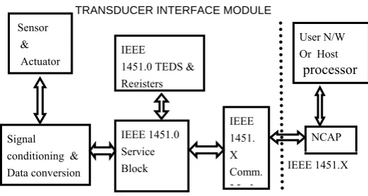
The IEEE 1451.0-2007 standard provides the reference model describing common functions, communication protocols and TEDS formats. The functional blocks of the reference model are shown in figure 1. Transducers (sensors and actuators) along with the signal conditioning and data conversion units form the major part of the TIM. There is a separate storage area for the TEDS. Service commands are executed by a suitable architecture and serve for calibration, triggering and synchronous sampling of sensors and actuators,
B.Umamaheswari is with the Electrical and Electronics Engineering Department, College of Engineering Guindy, Anna University, Chennai- 25, Tamil Nadu, India. (Corresponding author – phone – 91 044 22357803, email – [email protected])
J.Kamala is with the Electronics and Communication Engineering Department, College of Engineering Guindy, Anna University, Chennai- 25, Tamil Nadu, India. (email – [email protected])
read, write and update of TEDS information. NCAP is an external unit to TIM, which supports all standard communication protocols and physical media defined by the host.
Research literature available in the area of smart transducer interface can be classified into three major categories namely, 1. Application of TIM into various fields 2. Proposal of dedicated electronic data sheets for specific applications. 3. Effective utilization of electronic data sheets. This paper falls in effective use of the standard.
These smart transducers and actuators find various applications ranging from simple traffic signal controllers to complex rocket system. K. Lee et al developed an IEEE 1451 based smart motor for vehicles and showed that the IEEE based smart module, supports modular architecture for easy replacement of sensor in case of failure [2]. However an increase in delay time is reported due to processing involved. Kularatna et al designed, a low cost IEEE 1451 based system to monitor gas pollutants with plug-and-play capability, using microconvertor [3]. Depari et.al proposed, a single chip Smart Transducer Interface Module (STIM) architecture capable of communicating through USB interface, for gas and vapor detection, which has advantage over the usual Transducer Independent Interface (TII) [4]. Wall et al designed, a traffic signal control system with better operating frequency, that provides detailed information of sensor to the controller, which is not part of TIM [5]. A low power, transmit only wireless sensor, capable of transmitting TEDS information in SNAP (Scaleable Node Addressable Protocol) format is developed and tested for medical application by Wobshall et al [6].
Transducer Interface Module for Smart Control
of DC/DC Converter System
B. Umamaheswari and J. Kamala
G
Sensor &
Actuator
Signal conditioning & Dataconversion
IEEE 1451.0 Service Block
IEEE 1451. X Comm.
M d
IEEE 1451.0 TEDS & Registers
NCAP User N/W Or Host
[image:1.595.306.567.264.403.2]processor TRANSDUCER INTERFACE MODULE
Figure 1. IEEE 1451.0-2007Standard
Jethwa et al developed a dedicated electronic data sheet namely Health Electronic Data Sheet (HEDS), to detect faulty sensors. Control algorithms are developed for two cases of faulty sensors, namely the dead sensor and the noisy sensor. According to the type of fault identified, corresponding activating signals are applied to actuators [7]. In the earlier paper of authors, the effective use of TEDS is demonstrated for storing of system parameters and for estimation of the system variables [8]. The IEEE 1451.0-2007 standard describes variety of TEDS like Transfer Function TEDS, Frequency Response TEDS, Calibration TEDS etc all meant for Sensors / Actuators. The purpose of incorporating a sensor actuator in a system is to control the system itself. Also the processing capability of TIM can be utilized beyond sensor / actuator calibration for the purpose of control. This has been the motivation for this paper to propose an integrated structure with an additional supervisory layer to switch between services and user application function. The novelty of the proposal lies in the use of User TEDS of IEEE standard for additional function. Application of sensor / actuator data sheet into various fields can be found in [9-15].
Integrating the control algorithm along with calibration/estimation of system parameters is considered in this paper. Implementation of single integrated TIM for control of DC/DC Converter system is presented. The novelty of the proposal lies in making effective use of IEEE 1451.0 service block and User TEDS for diagnostics and control of the given system. The TIM architecture can be reconfigured to suite any system by changing TEDS contents and controller parameters. The TEDS and control functions are configured to be complementary which eliminates the delay in controller performance. Section II describes the functional blocks of the DC/DC converter control system. Section III explains the proposed TIM architecture, formation of TEDS and memory allocation for each sensor/actuator TEDS. Implementation of various functional blocks in Field Programmable Gate Array (FPGA) is presented in section IV. Section V presents simulation results. Section VI concludes with the features, advantages and drawbacks of the proposed architecture.
II. DC/DCCONVERTERSYSTEM
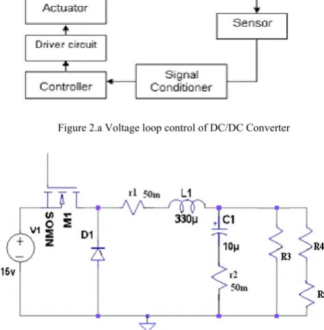
Let us consider the control of the DC/DC Converter system described in figure 2.a. The objective is to supply regulated voltage to the load. The actuating element is a thyristor switch of appropriate rating. Depending on the type of converter, the number of switching devices may vary. Depending on the cost and importance of application, type of sensors may vary from simple resistive sensor to Hall effect sensor. Resistive sensor is chosen when cost effective solution is opted. Current mode control of DC/DC converter requires two sensors, whereas the voltage mode control requires one sensor only.
A buck type of DC-DC converter as shown in figure 2.b is chosen with L = 330µH, C = 100µF to get regulated voltage of 3Vat 1A at the output. The load is considered to be resistive with R3= 3Ω. Voltage is sensed with the help of a potential divider. The important parameters of the voltage sensor are temperature coefficient, tolerance and the nominal values.
[image:2.595.320.526.72.226.2]The Power MOSFET IRFP 150N is used as actuator. The device is triggered by a driver circuit with proper isolation.
[image:2.595.311.548.126.368.2]Figure 2.a Voltage loop control of DC/DC Converter
Figure 2.b DC/DC Converter
III. THE PROPOSED TIMARCHITECTURE
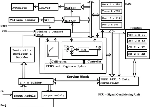
The detailed architecture of the proposed TIM is shown in figure 4. TIM includes sensors, actuators, signal conditioning blocks, memory for TEDS storage, registers and service area along with IEEE 1451.0 service routine. An input signal called ‘Mode’ decides the operating modes of the TIM, namely the IEEE 1451.0 Services and the User defined service. Either Command is applied / Data input is applied through input pin ‘Din’ and data output through ‘Dout’ signal.
A. Command ExecutionUnit
The command execution unit consists of input / output modules, buffers, instruction register and decoder, Timing and control unit and IEEE 1451.0 data formatter.
Timing and control unit provides two operating modes based on the input signal ‘mode’ as follows.
‘Mode’ =
Services
d
UserDefine
Services
IEEE
:
'
1
'
Figure 3. Proposed Integrated TIM Architecture
Service commands are decoded in the instruction decoder to activate memory blocks. Each command is of 56 bits (C0 –
C55) in length, which is grouped into eight octets (8 bits).
Instruction is formed according to destination transducer, command class, command function, length of command and the checksum. Major commands of the standard are Read/Write operation of TEDS, Registers, Transducers and TIM status. Instruction decoder provides appropriate control signals according to the instruction. Complete Architecture is developed to execute all necessary commands
A. Transducer Electronic Data Sheet Formation
TEDS are classified into 10 categories as per the IEEE standard, out of which, four are mandatory for each sensor / actuator. Table I lists the details of required TEDS for each sensor/actuator. The User Transducer name TEDS is one among them.
Basically User TEDS is not given any structure. Normally it is used to store the name of the transducer/actuator by which the system identifies it.
Effective use of User TEDS for storing the system data for state estimation and disturbance cancellation is presented in [16]. In this paper, it is utilized to provide smart readout of sensor and smart control through actuator. A standard format is presented for universal access of User TEDS. The proposed User TEDS of sensor is formed with the calibration details whereas the User TEDS of actuator is augmented with controller coefficients. For the DC/DC Converter example described in the previous section, User TEDS of size 160 bits will be sufficient for the actuator controlled by a first order system and 112 bits for the voltage sensor with linear calibration curve as described in Table II.a. The user TEDS is given a structure as given in Table II.b. In this structure the number of bits for length, identifier and checksum is fixed at 32, 48 and 16 respectively. Specific structure as given by Table II.b is introduced to store the calibration data and controller coefficients for universal access of data. Size of TEDS varies with the order of controller and calibration data of actuators and sensors. Controller is presented in the form of pulse transfer function and the calibration curve is considered as polynomial.
Instruction Register &
Decoder
Timing & Control Unit
I / O Buffer
Output Module
IEEE 1451.0 Data Formatting
Dout
Actuator Driver Buffer
Voltage Sensor
TSR 1 x 32
ESR 2 x 32
MR 2 x 32 CR 2 x 32
Meta 1 x 320
Trans 2 x768
User 2 x 112
PHY 2 x 10⁴
Input Module
Din Dclk Mode
SCU
TEDS
Registers
Buffer
TEDS and Register – Update
Service Block
∑ H(Z)
Calibration Controller
SCU – Signal Conditioning Unit
X(Z) Y(Z)
+
TABLE I:BASIC TEDS
TEDS Data Description Parameters used TEDS size Meta – TEDS Worst-case timing parameters,
number of transducers in TIM
Manufacturer name, place and id, time out operation 320 bits (pre defined) Transducer
Channel TEDS
Parameter being measured Operating range Characteristics of I/O Worst case error Timing information
Voltage sensor Sensor input – voltage Resistor values – ohms ADC bit size – 8 bits
Resistor tolerance – Deviation in O/P Actuator
Actuator output – voltage
Max. Gate Input Voltage & Drain current – I/O limits Rise Time and Fall Time – conversion time
768 bits (pre defined)
User’s Transducer Name TEDS
User Defined Voltage sensor Calibration details Actuator
Controller coefficients
80 + XX bits (User defined) 80 + XX bits (User defined) PHY TEDS Physical communication
medium
Host Interface
TABLE II.A. USER DEFINED PARAMETERS OF USER TEDS
Actuator Voltage sensor
Field number
Number of bits
Description Field number
Number of bits
Description
1 8 Number of Zeros 1 8 Number of polynomial coefficients 2 8 Bit size of numerator coefficients
3 8 Number of Poles 2 8 Bit size of coefficients 4 8 Bit size of denominator coefficients
TABLE II.B USER TEDS OF SENSORS / ACTUATORS
USER TRANSDUCER TEDS–160 BITS (ACTUATOR) USER TRANSDUCER TEDS–112 BITS (VOLTAGE SENSOR)
00 00 00 13 (32 bits) 03 04 00 0C 01 01 (48 bits) 01 10 01 10 0733 1000 (64 bits) FD 70 (16 bits)
Length
User transducer TEDS identifier User defined – Controller Coefficients Check sum
00 00 00 0E (32 bits) 03 04 00 0C 01 01 (48 bits) 01 10 1000 (16 bits) FF C7 (16 bits)
Length
User transducer TEDS identifier User defined – Sensor calibration data Check sum
IV.IMPLEMENTATION OF TIM IN FPGA
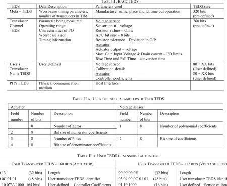
DC/DC converter described in figure 2.b is developed as per the choice of components presented in the earlier section. The voltage sensor output is interfaced to the system using ADC0804. The digital PWM output is applied to the gate of MOSFET with the help of appropriate driver circuits. FPGA implementation and the
complete experimental set up are shown in figures 4 and 5.
[image:4.595.68.519.53.422.2]
[image:4.595.322.553.457.694.2]
Figure 5 Experimental Set-up
Figure 4 FPGA implementation
Input Buffer
Signal Conditioning
Actuator IRPF 150N din
FPGA
TEDS & Registers IEEE 1451.0 Services & Command Decoder
IEEE 1451.0 compatible controller
ADC 0804
PWM Output
dout dclk
mode
Voltage Sensor
Atlys Spartan 6 FPGA Buck Converter
[image:4.595.45.283.560.728.2]Controller determines the error signal using reference input and output. Inputs are received through ADC 0804 chip and are of 8 bits in precision. Output of the controller is derived using Equation 1, which provide the PWM signal for actuator. Controller is designed to implement simple PI controller for voltage mode control of Buck converter.
e(n) = y(n) - ref (1) y(n) = a1e(n) + a2e(n-1) + b1y(n-1)
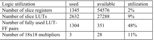
Hardware utilization of the Atlys Spartan 6 FPGA (XC6SLX45) [16] is provided in the synthesis report generated by the Xilinx tool [17] provided in Table III.
TABLE III :DEVICE UTILIZATION SUMMARY
Logic utilization used available utilization Number of slice registers 1345 54576 2% Number of slice LUTs 2632 27288 9% Number of fully used
LUT-FF pairs 1304 351 48%
Number of 18x18 multipliers 3 28 11%
V.SIMULATION RESULTS
Architecture is simulated for various IEEE 1451.0 service commands such as accessing TEDS, registers, sensors and activation of actuators. Execution of command is performed after receiving 56 bits of command (with offset field = 0) in the signal ‘din’ serial input line. Signals of interest are shown in the diagram 6. Command ‘Read Service Request Mask’ places the contents of service request mask on the output signal ‘dout’ and it is shown in Figure 6.
Figure 6 Execution of command “Read Service Request Mask”
VI.CONCLUSION
The complete service function, calibration and control operations of TIM are implemented in FPGA. The proposed architecture effectively incorporates the end use of sensor/actuator functions in calibration and control of the given system. With parallel interface and processing, faster operations of functional modules are achieved. TEDS of smart transducers are configured within the FPGA for fast access and is very useful to store the details of system. Single chip solution of the architecture is possible with moderate design effort. The architecture is supported by all the advantages of FPGA.
REFERENCES
[1] IEEE Standard for a Smart Transducer Interface for Sensors and Actuators – Common Functions, Communication Protocols, and Transducer Electronic Data Sheet (TEDS) Formats, IEEE Standard 1451.0-2007.
[2] Kyung Chang Lee, Man Ho Kim, Suk Lee, Hong Hee Lee, “ IEEE-1451-Bsed smart Module for In-vehicle Networking Systems of Intelligent Vehicles”, IEEE Transactions on Industrial Electronics, Vol. 51, No. 6, pp. 1150-1158, Dec. 2004.
[3] Nihal Kularatna, B. H. Sudantha “An Environmental air Pollution Monitoring System Based on the IEEE 1451 Standard for Low Cost Requirements”, IEEE Sensors Journal, Vol. 8, no. 4, pp. 415-422, Apr.2008.
[4] Alessandro Depari, Paolo Ferrari, Alessandra Flammini, Daniele Marioli, Andrea Taroni, “A VHDL Model of IEEE1451.2 Smart Sensor: Characterization and Applications,” IEEE Sensors Journal, Vol. 8, No. 5, pp. 619-625, May 2007.
[5] Richard W. Wall, Andrew Huska, “Design Platform for Plug-and-Play IEEE 1451 Traffic Signal”,
”
Industrial Electronics Society, pp. 427-432, IECON2005.[6] Darold Wobshall and S. Mupparaju, “ A Low-Power Wireless Sensor with SNAP and IEEE 1451 Protocol”, Sensors Applications Symposium – 2008, Atlanta, Georgia,USA, Feb 12-14, 2008.
[7] Dipan Jethwa, Rastko R. Selmic and Fernando Figueroa, “Real-Time Implementation of Intelligent Actuator Control with a Transducer Health Monitoring Capability”, 16th Mediterrannanean Conference on Control and Automation, Congress Centre, Ajascio, France, June 25-27, 2008.
[8] J. Kamala and B. Umamaheswari, “ IEEE 1451.0-2007 Compatible Smart Sensor Readout with Error Compensation using FPGA”, Sensors and Tranducers Journal, Vol. 102, Issue 3, pp. 10-21, Mar. 2009.
[9] J. Kim, K. Lim, J. Hu and W. Kim, “ A Study on the implementation of the IEEE 1451 on a biomedical sensor network for e-Health” ICACT2006, Feb. 20-22, 2006.
[10] L. E. Eccles, “The Need for Smart Transducers: An Aerospace Test and Evaluation Perspective”, IEEE Instrumentation and Measurement Magazine, pp. 23-28, Apr. 2008
[11] Anuj Kumar, I. P. Singh, and S. K. Sud, “Energy Efficient and Low-Cost Indoor Environment Monitoring System Based on the IEEE 1451 Standard”, IEEE Sensors Journal, Vol. 11, No. 10, pp. – 2598-2610, October 2011
[12] A. Stepanenko, K. Lee, R. Kochan, V. Kochan and A. Sachenko, “Development of a Minimal IEEE 1451.1 Model for Microcontroller Implementation”, SAS 2006- IEEE Sensors Applications Symposium, Houston, Texas, USA,7-9 Feb. 2006.
[13] L. Bissi, P. Placidi, A. Scorzoni, I. Elmi, and S. Zampolli, “Environmental monitoring system compliant with the IEEE 1451 standard and featuring a simplified transducer interface”, Sensors and Actuators A 137, pp. 175–184, 2007
[14] J. D. Kim, J. H. Lee, Y. K. Ham, C. H. Hong, B. W. Min, and S. G. Lee, “Sensor-Ball system based on IEEE 1451 for monitoring the condition of power transmission lines”, Sensors and Actuators A 154, pp. 157–168, 2009.
[15] P. Ferrari, A. Flammini, D. Marioli, and A.T aroni, “A low-cost Internet-enabled smart sensor,” in Proc. IEEE Sensors 2002, Orlando, FL. Jun. 12-14, 2002, vol. 2, pp. 1459-1554.
[16] Xilinx Spartan®-6 LX45 FPGA, Atlys Board Reference Manual [Online] Available : www.digilentinc.com
[image:5.595.44.292.239.303.2]