132
©IJRASET: All Rights are Reserved
Effect of various Design Parameters and
Development of Engine Muffler in IC Engine
Prof. Saurabh Wanjari1, Swapnil Nikam2 1
Mechanical Engineering Department RMD Sinhgad Technical Campus, Savitribai Phule Pune University
Abstract:In our present time, chop-chop increasing setting one amongst the developing issues is that of "Noise". the aim of this seminar is to check the harmful effects of noise on groups of people. In India, the transportation sector is growing chop-chop and range of vehicles on Indian roads is increasing at in no time rate. This has cause overcrowded roads and pollution. Engine noise is one amongst the key sources of noise in vehicles. Mufflers area unit unremarkably wont to minimize sound transmissions caused by exhaust gases. The muffler is a vital part of the trendy vehicle exhaust. so muffler style becomes a lot of and a lot of vital in noise reduction. the acceptable style and development can facilitate to cut back the amplitude, however at same time the performance of the engine mustn't be hampered by the rear pressure caused by the muffler
Keywords:Muffler; petrol engine; design parameters; development.
I. INTRODUCTION
Social surveys have shown that a predominant think about nuisance estimate is that the noise. By definition noise is unwanted sound. Noise affects creature in variety of the way. there's impact of noise on speech. there's bound physiological impact of noise. Noise has the link with the annoyance and performance of creature. Noise could be a nuisance for gift day urban society. Because the invention of the interior combustion engine, the noise created by it's been a continuing supply of downside to the atmosphere. therefore the issues of reducing engine noise consist, principally in attenuating exhaust noise. smart style of the muffler ought to provide the simplest noise reduction and provide optimum backpressure for the engine. the method for planning a muffler can be prolonged and troublesome because it involves a a lot of iteration with totally different prototypes. sound pollution created by engines becomes an important concern once utilized in residential areas or areas wherever noise creates hazard. Mufflers are developed over the previous few years supported electro- acoustic analogies and experimental trial and error.
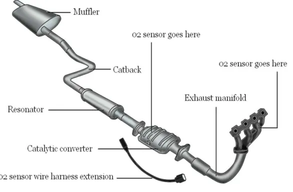
Main Components Of Exhaust System
A. Exhaust manifold , placed at the initial position of exhaust system.
B. Catalytic converters , placed just after manifolds.
C. Mufflers and Resonator.
[image:1.612.165.458.514.706.2]D. Tail Pipe.
133
©IJRASET: All Rights are Reserved
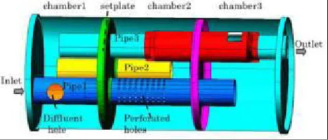
[image:2.612.191.430.78.180.2]Fig 2 : Schematic diagram of muffler
The basic constructions of muffler sometimes carries with it the hollow metal jacket, perforated tubes and therefore the enlargement chamber. The arrangement of those parts can guide the exhaust gas to ensue the recess pipe of the muffler to the outlet (tail pipe). within the muffler, the noise from the exhaust gas are reduced by dissipation of the wave energy, reflection of the wave energy towards the engine or the mix of the 2. Today's vehicles square measure equipped with 2 styles of muffler, either the reflective muffler that consists of variety of hollow components of various thwart wise dimensions joined along thus on cause, at each junction, electric resistance match and thence reflection of considerable a part of the incident acoustic energy back to the supply or the dissipative muffler that carries with it ducts lined on the within with acoustically assimilating materials. each mufflers square measure having completely different construction, geometry, and principles in their application. The performance of a muffler is represented by the Insertion loss, Transmission loss and Back pressure.
Generally Associate in Nursing exhaust muffler ought to satisfy some basic needs like adequate insertion loss, low back pressure, ideal muffler size that may have an effect on the price and accommodation and also the last one might be the sturdiness to face up to rough conditions and intensely high temperatures. therefore some style issues ought to be taken so as to come back up with Associate in Nursing optimum muffler style. The parameters that govern the performance of the muffler area unit the muffler chamber style, restrictions of the flow of the exhaust gasses and also the material of the muffler itself. the link between the noise and also the back pressure is reciprocally proportional; lowering the amplitude at the tip can end in high back pressure. However, this relationship is undesirable because the demand is to own a quiet muffler with a tiny low back pressure. the upper the rear pressure created by the system, the less is that the web power offered on the shaft and therefore the a lot of is that the specific fuel consumption. Vehicle engines generate noise as a result of the pressure wave created throughout the (sudden) gap of the exhaust valves of the engine. The noise is unwanted. as a result of exhaust noise should meet legislation targets, client expectations and price reduction that imply style optimisation of the exhaust systems within the style section. One of the elements within the system of a vehicle is that the muffler. The arrangement of those elements can guide the exhaust gas to ensue the water pipe of the muffler to the outlet (tail pipe) within the muffler; the sound/noise energy is absorbed by muffler lining, or mirrored back to the engine before the gas flows bent on the atmosphere. The noise cancellation can scale back the noise that radiated by the vehicle to the encompassing. The noise from the system consists of 3 elements : 1. Pulsation noise 2. Flow generated noise returning from the passage of the muffler outlet 3. Generally, mufflers fitted to such engines area unit basically reactive devices as opposition being dissipative devices. much reactive mufflers even have some dissipative operate. a perfect muffler for reciprocal burning engines functions as a coffee pass filter. The mean flow ought to be allowed to pass unobstructed through the muffler with the acoustic pressure fluctuation is reduced. If the steady flow is obstructed the so-called’ back pressure’ are higher and also the engine can operate less with efficiency. It is desirable to be able to predict the pressure drop related to the steady flow through the muffler. it's additionally desirable to be able to predict the acoustic performance of the muffler. basically this suggests deciding as a operate of frequency however harmonically varied pressure fluctuations at the water of the muffler area unit attenuated before they emerge at the outlet.
II. LITERATUREREVIEW
" Ankit Singh, Dr. Nitin Shrivastava " , in the paper titled "Study of noise behaviour on mufflers for IC engines" states that , by using mufflers we can save the power and reduce the knock in the IC engine. [1]
" M. Rahman, T. Sharmin, A F M E. Hassan, and M. Al Nur", in the paper titled " Design and construction of muffler for engine exhaust noise reduction" states that, the conventional design of side branch resonator makes the muffler usable with engines having limited space. [2]
134
©IJRASET: All Rights are Reserved
characteristics of its exhaust muffler predicted using one dimensional computational fluid dynamics validates the results of the simulation. [3]
III. ACOUSTICANDMUFFLER
Acoustic may be a science of sound, which incorporates its generation, transmission and reception of energy as waves in matter. A muffler is also represented as any section of duct or pipe that has been formed or treated with intention of reducing transmission of sound.
A. The Nature of Sound
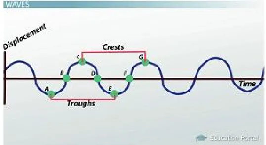
[image:3.612.176.445.218.365.2]Sound waves can't be transmitted through vacuum. The transmission of sound needs a minimum of a medium, which may be solid, liquid, or gas.
Fig. 1.Vibration waves with respect to time
B. Basic properties of Waves 1) Frequency
2) Period 3) Wavelength 4) Speed of Sound
5) Partical Velocity 6) Acoustic Impedence 7) Sound Intensity
C. Levels
The fundamental purpose of grade scale is to relate power, intensity, or energy density to a log of the magnitude relation of that amount to the reference amount to the reference amount. To preserve constant proportion accuracies in measure or describing these quantities and to avoid massive exponents in numbers concerned, exponent scales square measure used. The log most typically related to acoustics is that the sound unit. The argument in log is that the dimensionless and scale is alleged to offer the extent of sound in decibels(dB), higher than or below the reference level that's determined by reference amount.
1) Sound power level: Sound power level is defined as
Lw = 10 dB
where,
W = sound power, watts, = Reference sound power, ,watts
2) Sound intensity level: Sound intensity level in decibels is defined by
135
©IJRASET: All Rights are Reserved
where,
I = Sound intensity, in watt/ , = Reference intensity standardized as watt/
3) Sound pressure level: The ratio between the greatest sound pressure that person with normal hearing may tolerate without pain. Most sound measuring instruments respond to sound pressure and the word decibel is commonly associated with sound pressure level. Sound pressure level is usually shortened
SPL = = 20
= 10
where,
= Reference rms sound pressure usually 2 x N/ , P = Sound pressure in N/ .
4) Mechanism of exhaust Noise Generation: The engine exhaust noise is the noise radiated from the engine exhaust pipe by the pressure pulsations due to sudden opening of the exhaust value and the turbulent motion of exhaust gas in the pipe. The exhaust process generates a series of noise pulses with the largest component at the firing frequency . An analysis of exhaust noise pattern of a petrol engine showed large peaks just above and below firing frequency. There may be some harmonies of the firing frequency present.
= Hz (four stroke engine)
= Hz (two stroke engine)
where,
N = Engine speed in rpm , Z = Number of cylinder in exhaust system.
D. Theory of Acoustical Mufflers
The muffler quiets the noise of the exhaust by "muffling" the sound waves created by the gap and shutting of the exhaust valves. once Associate in Nursing valve opens, it discharges the burned gases at high pressures into the piping, that is at depression. this sort of action creates sound waves that travel through the flowing gas, moving abundant quicker than the gas itself ,that the resonator and muffler should silence.
1) Absorptive Muffler: Absorptive mufflers are those mufflers that uses for sound attenuation by sound engrossing materials. They dissipate the acoustic energy into energy through the utilization of porous materials as mineral fiber. The necessary tools of thirsty mufflers ar absorbent material modelling and numerical computation. These mufflers that incorporate sound engrossing materials to remodel acoustic energy into heat. not like reactive mufflers that use damaging interference to attenuate radiated sound power, thirsty mufflers ar usually straight through pipes lined with multiple layers of thirsty materials to scale back radiated sound power. the foremost necessary property of thirsty mufflers is that the attenuation constant. higher attenuation constants cause additional energy dissipation and lower radiated sound power.
2) Advantages of Absorptive Mufflers
a) High quantity of absorption at larger frequencies.
b) sensible for applications involving broadband (constant across the spectrum) and narrowband noise.
3) Disadvantages of Absorptive Mufflers:- a) Poor performance at low frequencies.
136
©IJRASET: All Rights are Reserved
E. Applications of Absorptive Mufflers:-
There unit form of applications for spongy mufflers. the foremost documented application is in race cars, where engine performance is desired. spongy mufflers don't manufacture Associate in Nursing outsized amount of back pressure to attenuate the sound, that ends up in higher muffler performance. It got to be noted however, that the radiate sound is far higher. completely different applications embody plenum chambers , line ducts, and ventilation systems.
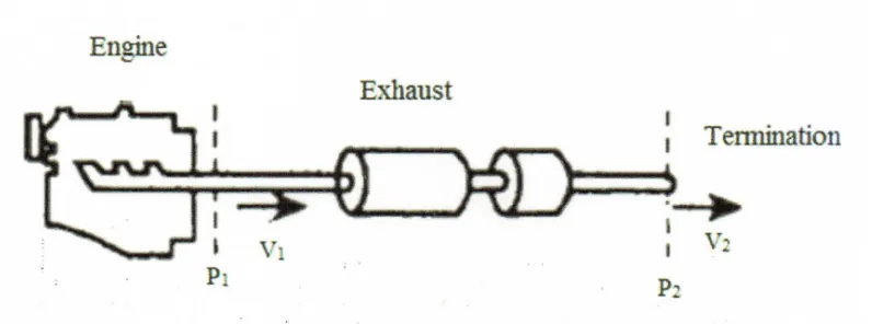
[image:5.612.110.508.185.333.2]It usually can this by ever-changing the wave energy into heat by passing the exhaust gas and its connected wave pattern, through perforated tubes and standardization chambers. Passing into perforations and reflectors within the chamber forces the sound waves to dissipate the energy.
[image:5.612.127.490.365.498.2]Fig. 2 Typical engine exhaust system
Fig.3 Dissipative (absorption) muffler
There is a number of empirical formula for quick hand calculation of transmission loss of lined ducts. One popular example is pining empirical formula according to which
TL = 1.5 α l
where,
P = Perimeter of ducts (inside the lining), in m.
S = Cross sectional area of duct (inside the lining), in m. l = Length of duct, in m.
α = Absorption coefficient of lining material obtained from laboratory measurement.
F. Reactive muffler
137
©IJRASET: All Rights are Reserved
energy back toward the engine accomplished by introducing changes in cross sectional areas i.e discontinuities and by suggests that of short branches gap into massive chambers. reflective the incident sound waves back toward the engine end in the formation of the standing waves within the exhaust pie between manifold and mufflers. The standing waves ar unceasingly bolstered throughout the operation of engine till non-lineraties take over and therefore the sound energy is dissipated within the sort of heat. These mufflers ar created with the series of chambers, that ar interconnected with pipes, perforated plates. due to reactive muffler in observe tends to own the next back pressure than dissipative muffler. However, the rear pressure of most offered muffler is therefore low that the result on engine HP is tokenish.
Fig.4 Reactive Muffler
1) Advantages of Reactive Muffler a) Good noise reduction.
b) Better attenuation.
2) Disadvantages of Reactive Mufflers a) Poor performance at low frequencies.
b) Material can degrade under certain circumstances (high heat, etc ).
IV. DESIGNPARAMETERS
A. Design considerations of Mufflers: 1) Acoustical considerations
a) Larger the area ratio of the chamber, the greater would be insertion loss.
b) In general, the sharper the discontinuity the more the insertion loss.
c) Muffler with extended tube chamber is on the whole better than those with simple chamber.
d) Better performance at lower frequencies is obtained as the thickness of the absorbing material is increased.
2) Acoustical performance parameters:
Following are the parameters used to describe the acoustical performance of muffler.
a) Insertion Loss[IL]: Insertion loss is the difference between two sound pressure levels measured at the same points in the space before and after a muffler as shown in fig .4 . Insertion loss depends on source and terminating impedance. Mathematically insertion loss can be expressed as
IL = - dB
where,
= Sound pressure level measure at the same point in space with no muffler, dB.
138
©IJRASET: All Rights are Reserved
b) Transmission Loss[TL]: Transmission loss is the ratio of the sound power incident on the muffler to the sound power transmitted by the muffler. The transmission loss is not affected by the terminating impedance. Mathematically transmission loss can be expressed as
TL = 10 dB
where,
= Sound power incident on the muffler, dB.
= Sound power transmitted by the muffler, dB.
c) Noise Reduction [NR]: Noise reduction is the difference between the sound pressure level as measured at source side of a muffler and the sound pressure level measured at the receiving side. Noise reduction can be expressed mathematically as
NR = - dB
where,
= Sound pressure at the source side of muffler, dB.
= Sound pressure level at the receiving or exit side, dB.
IL = - dB
Fig.5. Definition of insertion loss
B) Aero-dynamic considerations
a) In several applications, the incoming flow distribution into a silencer isn't uniform, to Illustrate, for silencers set at downstream of elbows, diffusers, or valves, etc. If the recess flow for a silencer isn't uniform, adverse effects square measure to expected.
b) Secondly, the pressure drop across the silencer are higher; this may have an effect on the system performance.
c) If pressure drop isn't a difficulty, to Illustrate, in engine check cell flow and gas vent flow, the flow will be created uniform by adding correct flow resistance.
C) Mechanical considerations
a) Mechanics of manifold seal Design: The mechanisms of seal style formation is especially depends on the protection stress is generated at a protection joint. the desired pressure and cargo should be generated at contact place by the bolts therefore offer the adequate protection, for face up to the opposite masses too-vibrations and thermal expansions. The manifold behaviour can be understanding through vibration, compressive load of bolt and thermal growth mechanisms.
b) Vibrations: manifold is subjected to vibrations attributable to the mechanical phenomenon reciprocator associated motion of elements gift in an engine assembly. The manifold has its own natural frequency that resulted in vibrations. This natural vibration produces deflection within the manifold which can seem as bulging of headers at high temperatures. The unsteady thermal mass across the manifold ends up in vibrations likewise. so the seal style needs to be created so as to see the resilience of waterproofing. The vibration mechanics area unit thought of by finding out natural frequency and vibration fatigue mechanism.
139
©IJRASET: All Rights are Reserved
D) Geometrical considerations
a) Adequate Insertion Loss: the most practical of a muffler is to “muffle” or attenuate sound. an efficient muffler can cut back the force per unit area of the noise supply to the desired level.
b) Backpressure: Backpressure represents the additional static pressure exerted by the muffler on the engine through the restriction in flow of exhaust gasses. usually the higher a muffler is at attenuating sound the a lot of backpressure is generated.
c) Size :The out there house encompasses a nice influence on the scale and so style of a muffler which will be used. A muffler might have its pure mathematics designed for optimum attenuation but if it doesn't meet the house constraints, it's useless.
d) Durability: The lifespan of a muffler is another vital practical demand particularly once coping with hot exhaust gasses and absorbent silencers that ar found in performance vehicles.
E) Economical considerations
a) The size of production of a product can influence its fastened prices like machinery. notwithstanding the amount created, there'll continually be constant value for the machine. Therefore, the a lot of product one will turn out at constant prices, the a lot of the charge per unit can decrease, that ultimately allows the corporate to relish economies of scale.
b) These economies of scale ar advantageous for an organization as a result of it will build them charge constant costs and increase profits per unit or it will decrease its product's value and consequently sell a lot of of it, that additionally will increase profit.
c) Advertising associate degreed selling is additionally an example of a set value as a result of notwithstanding what number units an organization sells of a product, the promotion can continually be constant value, i.e. it's not correlative with the increase/decrease of producing.
d) Variable prices on the opposite hand ar prices in correlation with the assembly. Examples are the wages of the workmen, since the a lot of they work, the a lot of they get paid.
e) the prices of raw materials, sales and distribution also are samples of variable costs. Production prices like the quantity of materials used for producing also are variable costs.
V. CONCLUSION
Different types of muffler and planning parameters like acoustic, Aero-dynamical, Mechanical, Geometrical and Economical and it's effects on the performance of engine area unit studied. The vehicle muffler ought to be designed to fulfil all useful needs as mentioned higher than, particularly adequate insertion loss, minimum back pressure, house constraints, be durable, turn out the required sound, be price effective, and be esthetical pleasing there'll be several potential muffler style solutions for a selected state of affairs and plenty of potential ways in which to predict a mufflers insertion loss however the look is established by its performance on associate automobile. Reasonably, selecting the lengths of extended inlet/outlet tubes and inter-connecting tube could acquire desired broadband high noise attenuation characteristics the twin inter-connecting tubes improve the acoustic attenuation performance of the silencer at higher frequencies.
REFERENCES
[1] "DESIGN AND CONSTRUCTION OF A MUFFLER FOR ENGINE EXHAUST NOISE REDUCTION" by M. Rahman, T. Sharmin, A F M E. Hassan, and M. Al Nur.
[2] "STUDY OF NOISE BEHAVIOR ON MUFFLERS FOR IC ENGINE: A REVIEW " by Ankit Singh*, Dr. Nitin Shrivastava.
[3] The efficient acoustic analysis of silencers of any general geometry by John F. Dowling, Keith S.Peat.