Abstract — In this paper we are presenting some results of the singularity analysis of the new parallel manipulator with cylindrical joints. We have derived the differential kinematic relations between two vectors: mobile-platform velocity and the active-joint rates. These relations comprise two matrices, the forward - and the inverse - kinematics Jacobians. The analytical approach to the research of these relations, based only on linear algebra, has yielded interesting results on identification of the singular configurations of the parallel manipulator.
Index Terms — Jacobian matrix, mobile platform, parallel manipulator, singularity analysis.
I. INTRODUCTION
Parallel manipulators in comparison with serial manipulators have big carrying capacity, high velocities and positioning accuracy [1]. However, parallel manipulators have many singularity configurations in which they cannot carry out their functional tasks [2]. Gosselin and Angeles [3], Tsai [4] describe three types of singularity, based on the properties of the Jacobian matrices. The Jacobian of a parallel manipulator can be divided into two matrix: one matrix Jx
associated with the direct kinematics and the other matrix Jq
associated with the inverse kinematics.
In this paper some results for identification of the singularity configuration of a parallel manipulator with cylindrical joints (PM 3CCC) based on research of degeneration of Jacobian matrices are presented.
II. GEOMETRY OF A PM3CCC
A PM 3CCC is formed by connection of a mobile platform 3 with a base 0 by three spatial dyads АВС, DEF, GHI of kind СCС, where C - cylindrical joint (Fig. 1). A spatial kinematic chain with two links and three kinematic pairs is called a spatial dyad which has zero degree-of-freedom. As a spatial dyad has zero degree-of-freedom it does not impose restriction on a mobile platform 3 and six degree-of-freedom of a mobile platform is remained. Each cylindrical joint has two degree-of-freedom: one rotation and one translation. Six movements of input cylindrical joints A, F, I (three rotations and three translations) are generalized coordinates of a
Manuscript received March 22, 2012; revised April 13, 2012.
Zh. Zh. Baigunchekov is with the Department of Science, Kazakh-British Technical University, Almaty, Kazakhstan (phone: +7(727)-2-727-572; fax: +7(727)-2-720-489; e-mail: [email protected]).
M. B. Izmambetov is with the Research Laboratory of Mechatronics and Robotics, Kazakh-British Technical University, Almaty, Kazakhstan (e-mail: [email protected]).
parallel manipulator with cylindrical joints PM 3CCC.
A PM 3CCC is intended for reproduction of movement of a mobile platform 3 or the frame PXPYPZP attached to it with respect to base frame UoVoWo
(),
(),
() , ) ( ,) ( ,
) (
0 0 0
0 0
0
0 0 0
0 0
0
t t
t
t W W t V V t U U
P P P
P P
P
P P P
P P
P
q q
q
q q
q
(1)
where q(t)=[7(t), s7(t),8(t), s8(t),9(t), s9(t),]T - a vector of
[image:1.595.320.542.349.564.2]the input generalized coordinates; 0P, 0P и 0P - the components of relative orientation of coordinate systems PXPYPZP and OUoVoWo.
Fig. 1. Parallel manipulator with cylindrical joints PM 3CCC
For definition of constant and variable parameters of parallel manipulator we fixed the right Cartesian coordinate systems UVW and XYZ to each element of each joint. The axes W and Z of coordinate systems UVW and XYZ are directed on a axis of rotation and translation of cylindrical joints.
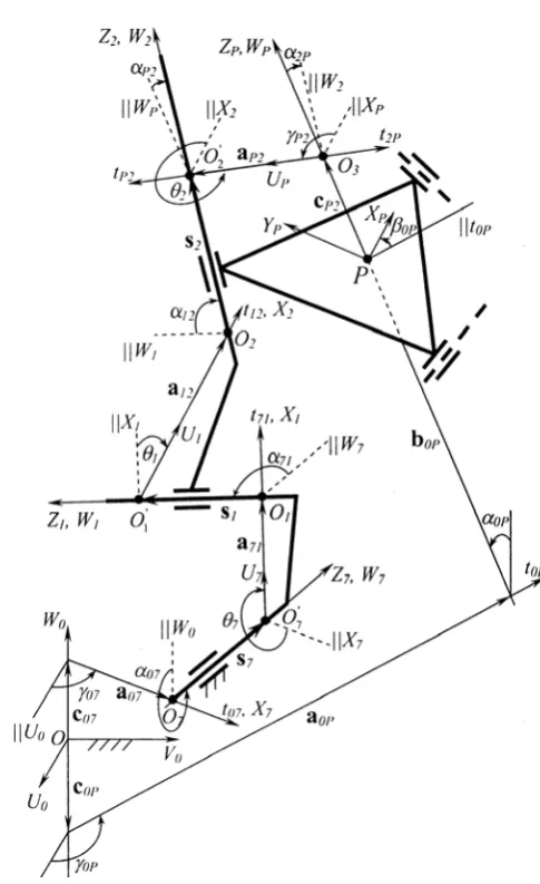
Transformation matrix Tjk between coordinate systems UjVjWj and XkYkZk fixed on the ends of binary link jk has a view (Fig. 2)
jk( jk, jk, jk, jk, jk, jk)
jk T a b c
T
Singularity Analysis of a Parallel Manipulator
with Cylindrical Joints
Zhumadil Zh. Baigunchekov, and Myrzabay B. Izmambetov
U0
V0 W0
O
A 0
5
2 6
4 3
9
8
9
s
8
s
7
s
1 7
B C
D
E
F
G
H
I
7
Р XP
Fig. 2. Binary link jk of kindCC
=
44 43 42 41
34 33 32 31
24 23 22 21
14 13 12 11
t t t t
t t t t
t t t t
t t t t
=
k j k jτ R
0 1
, (2)
where t111,t12 t13t140,
jk jk
jk jk
jk b
a
t21 cos sin sin , jk jk jk
jk jk
t22cos cos sin cos sin , jk jk
jk jk
jk
t23cos sin sin cos cos , jk
jk
t24 sin sin ,
jk jk
jk jk
jk b
a
t31 sin cos sin , jk jk
jk jk
jk
t32sin cos cos cos sin , jk jk jk
jk jk
t33cos cos cos sin sin , jk
jk
t34cos sin , t41cjkbjkcosjk , jk
jk
t42sin sin , t43sinjkcosjk, t44cosjk. The following six parameters define the relative positions of the two coordinate systems
U
jV
jW
jand XkYkZk:ajk- a distance from axis Wj to axis Zk which is measured along the direction of tjk; tjk – a common perpendicular between axes Wj and Zk; jk- an angle between positive directions of axes Wj and Zk which is measured counter clockwise relatively to positive direction of tjk; bjk - a distance from direction of tjk to direction of the axis Xk which is measured along positive direction of an axis Zk; jk - an angle between positive directions of tjk and axis Xk which is measured counter clockwise relatively tо positive direction of axis Zk; cjk- a distance from direction of an axis Uj to direction of tjk which is measured along positive direction of an axis Wj; jk- an angle between positive directions of axis Uj and tjk which is measured counter clockwise relatively to positive direction of an axis Wj.III. GENERATION OF JACOBIAN MATRICES
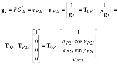
3PMCCC has same three legs of kind CCC. Let’s consider the i-th leg which has a kinematic chain
P
O
O
O
O
O
O
OO
i i i i i 'i 3i2 2 ' 1 1 ' 7
7 (Fig. 3). A loop-closure
equation for the kinematic chain
PO O O O O O O
OO7i 7'i 1i 1'i 2i 2'i 3i can be written as
i i i i i i O
P r i s a s a s g
r 7 71 1 12 2
[image:2.595.320.563.274.671.2]7 , i1,2,3 , (3)
Fig. 3. Geometryof the i-th leg of a PM 3CCC
where
P P P
P P P
P P P P
c a a
0 0 0
0 0 0
0 sin
cos 1
0 0 0 1 1
1
T
r T
r (4)
k
Y
) ( jk k t Х
l
jk k О j
W
//
jk
а k
j
О
j
U j
j
V
k
Z
j
i P P i i P i P i
i PO c a g T g
g 2' 2 2 1 0 1
= i P i P i P i P i P P i P P c a a 2 2 2 2 2 0 2
0 sincos
1 0 0 0 1 T T
T (5)
Differentiating (3) with respect to time, we obtain
i i i i i i i i
P s7e7 θ7 r7 s1e1 θ1 a12
r
s2ie2i ωPfi, i1,2,3 (6)
where
T P P P T P P P
P U V W U V0 W0
0, ,
,
, 0 0
0
r - a vector
of velocity of a point Р; s7i s7ie7i , θ7i 7ie7i - vectors of velocity of the active joints;
i i i
i 71 1 12
7 a s a
r ; s1ie1i, θ1i 1ie1i , s2ie2i -
vectors of velocity of the passive joints;
TP P P
P U0, V0, W0
- a vector of angular velocity of a
mobile platform; fi PO2i gi s2i.
Dot-multiplying both sides of (6) by a12i leads to
7 ( 12 7 )
12Ti rP s i aTi e i
a
θ7ieT7i(r7ia12i)PT(fia12i), i1, 2,3 (7) Equation (7) can be presented in the matrix form
q J x
Jx q (8)
by using the notation
T
T P T P,r
x , q
s71,71,s72,72,s73,73
T,where the Jacobian matrices Jx and Jq are defined as follows
,
)
(
)
(
)
(
3 , 12 3 3 , 12 2 , 12 2 2 , 12 1 , 12 1 1 , 12
T T T T T Ta
f
a
a
f
a
a
f
a
J
x T T T T T T T ) ( 0 0 0 0 0 ) ( 0 0 0 0 0 ) ( 0 0 3 , 12 73 73 73 3 , 12 2 , 12 72 72 72 2 , 12 1 , 12 71 71 71 1 , 12 a r e e a a r e e a a r e e a JqIV. SINGULARITY ANALYSIS OF THE PMWITH 6DOF
For a PM 3CCC the first type of singularity corresponds to
the case when the matrix Jq has rank deficiency, i.e. when at
least the elements one of the rows of this matrix are zero. Then shall be fulfilled the following conditions
0 7 12 i T
i e
a , (9)
0 ) ( 7 12
7 i i
T i r a
e . (10)
From the first condition (9) a12ie7i is followed i.e. the
vector a12i determining the shortest distance between the
axes of passive cylindrical joints is perpendicular to the axis of the input cylindrical joint. It is easy to see that this is possible in cases
а) if 71i 0or , in always, (11)
b) if 071i , in only
1i
0
or
. (12)The case (11) defines the third type of singularity
configuration when a finite change of the coordinate s7i has
no effect on the movement of the platform (Fig. 4).
Fig. 4. The third type of singularity of the PM 3CCC
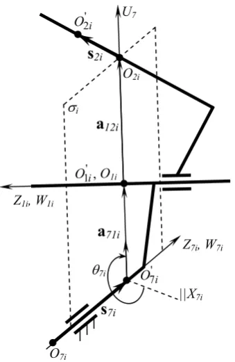
The case (12) implies that a12i ||a71i. At the same time the
condition (10) implies that the three vectors e7i, r7i, a12i
must lie either in parallel planes or in the same plane. This arrangement of these vectors, subject to (12) holds only when
the point O2i defining the end of the vector r7i lies in the
plane O7'iU7iW7i (this plane is denoted by i) (Fig. 5).
' 7i O U7 7i a71i O7i ||X7i Z7i, W7i O1i
s
7i a12iZ1i, W1i
[image:3.595.46.247.50.160.2]Fig. 5. The first type of singularity of the PM 3CCC
Since the vectors a12i, a71i determine the shortest
distance between the cylindrical joints, in this type of configuration the i-th leg is fully stretched or folded position. Therefore the set of Cartesian velocities of platform which
corresponds to the velocities of point O2i parallel to the
vectors a12i, a71i may not be reproduced. This set of the
Cartesian velocities is given by the set of rotation of platform around an arbitrary line in the plane containing the point
i
O2 and orthogonal to the vectors a12i, a71i. In addition,
any force applied to the platform and line of action which lies
in the i, and a pair of forces applied parallel to this plane do
not affect the rotational component of the i-th cylindrical actuator. This is explained by the fact that the moments of
force and a pair of forces with respect to the axis O7iZ7i, i.e.
relative to the axis of rotation of the input joint are zero.
The second type of singularity occurs when matrix Jx lacks
the range, that is when rows or columns of this matrix are linearly dependent. This type of singularities in contrast to the first is located inside the workspace. For the corresponding configuration of the PM3CCC the nonzero
output Cartesian velocities x of the platform are displayed in
the zero vector by conversion Jx. These speeds of platform
are possible even in still actuators of input joints. Let’s
rewrite the matrix Jx in the form
Z Y X Z Y X
Z Y X Z Y X
Z Y X Z Y X
n n n a a a
n n n a a a
n n n a a a
3 3 3 3 , 12 3 , 12 3 , 12
2 2 2 2 , 12 2 , 12 2 , 12
1 1 1 1 , 12 1 , 12 1 , 12
x
J , (13)
where the elements of the first three columns are the
components of one group of vectors a12i, and elements of
the last three columns - the second group of components of
the vectors ni fia12i relative to an inertial coordinate
system, i.e.
T iZ iY iX
i [a12 , a12 , a12 ]
12
a ,
T iZ iY iX i i
i f a12 [n ,n ,n ]
n , i1,2,3., (14)
For definiteness assume that the vectors gi lie in a plane
perpendicular to the axes of the platform and kinematic cylindrical joints of platform.
Consider the case where the three columns of vectors are linearly dependent. This case means that all the vectors of this group are parallel to each other and parallel to a common plane.
Let’s assume without proof the the following theorem.
Theorem. Two vectors laying in different and mutually intersecting planes are parallel if and only if each of these vectors are parallel to the line along which their planes are intersected.
The statement 1. The parallelism of all vectors ni ,
3 , 2 , 1
i is possible only if each of these vectors are parallel
to the axis PZP of the coordinate system PXPYPZP associated
with the mobile platform.
This statement means that in this case the vectors fi
anda12i, i1,2,3according to the definition of the vector
product of two vectors must lie in the plane РХРУР. Then all
cylindrical joints axis of the platform must also lie in the
plane РХРУР (this plane is denoted by Ω) (Fig. 6). Thus we
find that the last z-components of vectors a12i, i1,2,3
with respect to the local coordinate system PXPYPZP should
be zero, i.e. Pa12iZ 0, i1,2,3.
We can get the form (8) with respect to the coordinate
system PXPYPZP associated with the platform. For this case
the third, fourth and fifth columns of the matrix Jx will be
zero. Then the zero space of the matrix Jx is generated by the
vector [0, 0, 1, 1, 1, 0]T. This zero space corresponds to the
set of local rotations of the platform relative to an arbitrary
axis of plane PXPYP and local displacement along the axis PzP
with fixed actuators. In addition, the force acting along the
axis PzP and a pair of forces applied to the platform in a
parallel axis PzP of plane do not affect to actuators, i.e.
manipulator is not able to resist these loads.
The statement 2. All vectors ni , i1,2,3 can be
simultaneously parallel to one arbitrary plane if all axis of cylindrical joints of platform are orthogonal to this plane.
Assume that all axis of cylindrical joints are orthogonal to
the plane PXPYP of the platform (Fig.7). Then the vectors
i 12
a and ni i1,2,3 lie in planes parallel to the plane PXPYP
and therefore Pa12iZ 0 and PniZ 0, i1,2,3. That is
the third and fourth columns of the matrix Jx, compiled on a
system of coordinates PXPYPZP, will be zero. In this case the
zero space of matrix Jx is generated by vector [0, 0, 1, 1, 0,
0]T. This zero space corresponds to a local rotation of the
platform relative to the axis PZP and its finite movement
along the axis PZP with fixed actuators. In addition, the
i
' 7i
O U7
7i
a
71iO7i
||X7i Z7i, W7i O1i
s
7ia
12iZ1i, W1i ,
' 1i
O
' 2i
O
s
2iFig. 6. The second type of singularity of the PM 3CCC
Fig 7. The third type of singularity of the PM 3CCC
force acting along the axis PZP and a pair of forces applied to
the platform in a parallel axis PZP of a plane do not affect to
the actuators, i.e. parallel manipulator is not able to resist these loads.
Thus, we found another case that led to the singularity of the third kind when the axis of the cylindrical joints of the platform are perpendicular to its plane, which leads to the finite no controlled movements of platform in the orthogonal direction to the plane of platform in the fixed actuators.
V. CONCLUSION
On the basis of the equations of closed kinematic chains of the legs of a PM3CCC the velocity vectors are formed.
On the basis of the Jacobi matrix the conditions for the existence of singular configurations are defined and their geometrical and physical interpretations are given. These
results can be used in designing of construction of such manipulators. Besides the obtained conditions of configuration singularities can be expressed through constants and variable parameters of the parallel manipulator that is important for the control of such configurations.
REFERENCES
[1] J. P. Merlet, Parallel Robots, Kluwer Academic Publishers, London, 2000.
[2] Zh. Baigunchekov, and M.Izmambetov, "Singularity Analysis of the New Parallel Manipulator with 6 Degree-of-Freedom", World Congress on Engineering WCE2010, Proceedings, Vol. II, 2010, pp. 1472-1477.
[3] C. Gosselin, and J. Angeles, "Singularity analysis of closed-loop kinematic chains," IEEE Trans. Robotics & Autom., Vol. 6, No. 3, 1990, pp. 281-290.
[4] L. W. Tsai, Robot analysis: the mechanics of serial and parallel manipulators, John Wiley & Sons, Inc., New York, 1999.
Ω
XP YP
ZP
g2 а12,1
P а12,2
а12,3
g3 g1
XP YP
ZP
g1 а12,1
P g2
а12,2
g3
а12,3
[image:5.595.111.483.317.539.2]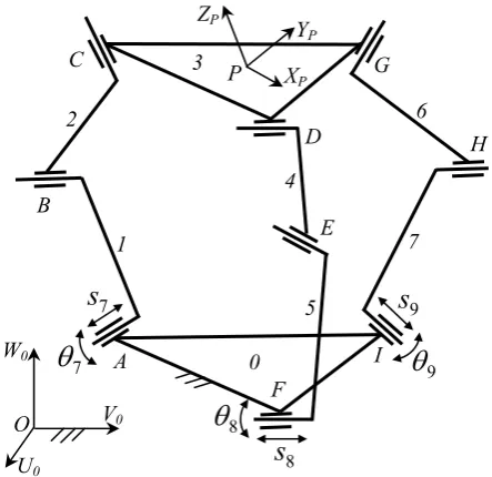

![Aand B are simultaneously singular. Tsai [2] has noted that matrix A is associated with the direct kinematics and matrix is](data:image/gif;base64,R0lGODlhAQABAIAAAP///wAAACH5BAEAAAAALAAAAAABAAEAAAICRAEAOw==)