NONRESIDENT
TRAINING
COURSE
December 1993
Electronics Technician
Volume 4—Radar Systems
DISTRIBUTION STATEMENT A: Approved for public release; distribution is unlimited.
Although the words “he,” “him,” and
PREFACE
By enrolling in this self-study course, you have demonstrated a desire to improve yourself and the Navy.
Remember, however, this self-study course is only one part of the total Navy training program. Practical
experience, schools, selected reading, and your desire to succeed are also necessary to successfully round
out a fully meaningful training program.
COURSE OVERVIEW
: In completing this nonresident training course, you will demonstrate a
knowledge of the subject matter by correctly answering questions on the following subjects:
Define
the
basic terms associated with radar and radar systems;
identify
the basic components of and
explain
the
operation of the Navy’s standard surface search radars, air search radars, three-coordinate air search radars,
carrier controlled approach (CCA) and ground controlled approach (GCA) radars, and planned position
indicators (PPI) and repeaters;
identify
the basic components of and
explain
the operation of identification,
friend or foe (IFF) systems, direct altitude and identity readout (DAIR) systems, naval tactical data (NTDS)
systems, and radar distribution switchboards; and
identify
and
explain
the safety hazards associated with
radar systems.
THE COURSE
: This self-study course is organized into subject matter areas, each containing learning
objectives to help you determine what you should learn along with text and illustrations to help you
understand the information. The subject matter reflects day-to-day requirements and experiences of
personnel in the rating or skill area. It also reflects guidance provided by Enlisted Community Managers
(ECMs) and other senior personnel, technical references, instructions, etc., and either the occupational or
naval standards, which are listed in the
Manual of Navy Enlisted Manpower Personnel Classifications
and Occupational Standards
, NAVPERS 18068.
THE QUESTIONS
: The questions that appear in this course are designed to help you understand the
material in the text.
VALUE
: In completing this course, you will improve your military and professional knowledge.
Importantly, it can also help you study for the Navy-wide advancement in rate examination. If you are
studying and discover a reference in the text to another publication for further information, look it up.
1993 Edition Prepared by
ETCS(SW) Linda Villareal
Published by
NAVAL EDUCATION AND TRAINING
PROFESSIONAL DEVELOPMENT
AND TECHNOLOGY CENTER
Sailor’s Creed
“
I am a United States Sailor.
I will support and defend the
Constitution of the United States of
America and I will obey the orders
of those appointed over me.
I represent the fighting spirit of the
Navy and those who have gone
before me to defend freedom and
democracy around the world.
I proudly serve my country’s Navy
combat team with honor, courage
and commitment.
CONTENTS
CHAPTER Page
1. Introduction to Basic Radar Systems. . . 1-1
2. Radar Systems Equipment Conjurations . . . 2-1
3. Radar System Interfacing . . . 3-1
4. Safety . . . 4-1
APPENDIX
I. Glossary . . . AI-1
II. References . . . AII-1
SUMMARY OF THE ELECTRONICS TECHNICIAN
TRAINING SERIES
This series of training manuals was developed to replace the Electronics
Technician 3 & 2 TRAMAN. The content is directed toward personnel working
toward advancement to Electronics Technician Second Class.
The nine volumes in the series are based on major topic areas with which the ET2 should be familiar. Volume 1, Safety, provides an introduction to general safety as it relates to the ET rating. It also provides both general and specific information on electronic tag-out procedures, man-aloft procedures, hazardous materials (i.e., solvents, batteries, and vacuum tubes), and radiation hazards. Volume 2,
Administration, discusses COSAL updates, 3-M documentation, supply paperwork,
and other associated administrative topics. Volume 3, Communications Systems, provides a basic introduction to shipboard and shore-based communication systems. Systems covered include man-pac radios (i.e., PRC-104, PSC-3) in the hf, vhf, uhf, SATCOM, and shf ranges. Also provided is an introduction to the Communications Link Interoperability System (CLIPS). Volume 4, Radar Systems, is a basic introduction to air search, surface search, ground controlled approach, and carrier controlled approach radar systems. Volume 5, Navigation Systems, is a basic introduction to navigation systems, such as OMEGA, SATNAV, TACAN, and man-pac systems. Volume 6, Digital Data System, is a basic introduction to digital data systems and incIudes discussions about SNAP II, laptop computers, and desktop computers. Volume 7, Antennas and Wave Propagation, is an introduction to wave propagation, as it pertains to Electronics Technicians, and shipboard and shore-based antennas. Volume 8, System Concepts, discusses system interfaces, troubleshooting, sub-systems, dry air, cooling, and power systems. Volume 9,
Electro-Optics, is an introduction to night vision equipment, lasers, thermal imaging,
INSTRUCTIONS FOR TAKING THE COURSE
ASSIGNMENTS
The text pages that you are to study are listed at
the beginning of each assignment. Study these
pages carefully before attempting to answer the
questions. Pay close attention to tables and
illustrations and read the learning objectives.
The learning objectives state what you should be
able to do after studying the material. Answering
the questions correctly helps you accomplish the
objectives.
SELECTING YOUR ANSWERS
Read each question carefully, then select the
BEST answer. You may refer freely to the text.
The answers must be the result of your own
work and decisions. You are prohibited from
referring to or copying the answers of others and
from giving answers to anyone else taking the
course.
SUBMITTING YOUR ASSIGNMENTS
To have your assignments graded, you must be
enrolled in the course with the Nonresident
Training Course Administration Branch at the
Naval Education and Training Professional
Development
and
Technology
Center
(NETPDTC). Following enrollment, there are
two ways of having your assignments graded:
(1) use the Internet to submit your assignments
as you complete them, or (2) send all the
assignments at one time by mail to NETPDTC.
Grading on the Internet:
Advantages to
Internet grading are:
•
you may submit your answers as soon as
you complete an assignment, and
•
you get your results faster; usually by the
next working day (approximately 24 hours).
In addition to receiving grade results for each
assignment, you will receive course completion
confirmation once you have completed all the
assignments.
To
submit
your
assignment
answers via the Internet, go to:
http://courses.cnet.navy.mil
Grading by Mail:
When you submit answer
sheets by mail, send all of your assignments at
one time. Do NOT submit individual answer
sheets for grading. Mail all of your assignments
in an envelope, which you either provide
yourself or obtain from your nearest Educational
Services Officer (ESO). Submit answer sheets
to:
COMMANDING OFFICER
NETPDTC N331
6490 SAUFLEY FIELD ROAD
PENSACOLA FL 32559-5000
Answer Sheets:
All courses include one
“scannable” answer sheet for each assignment.
These answer sheets are preprinted with your
SSN, name, assignment number, and course
number. Explanations for completing the answer
sheets are on the answer sheet.
Do not use answer sheet reproductions:
Use
only the original
answer
sheets that
we
provide—reproductions will not work with our
scanning equipment and cannot be processed.
Follow the instructions for marking your
answers on the answer sheet. Be sure that blocks
1, 2, and 3 are filled in correctly. This
information is necessary for your course to be
properly processed and for you to receive credit
for your work.
COMPLETION TIME
PASS/FAIL ASSIGNMENT PROCEDURES
If your overall course score is 3.2 or higher, you
will pass the course and will not be required to
resubmit assignments. Once your assignments
have been graded you will receive course
completion confirmation.
If you receive less than a 3.2 on any assignment
and your overall course score is below 3.2, you
will be given the opportunity to resubmit failed
assignments.
You
may
resubmit
failed
assignments only once.
Internet students will
receive notification when they have failed an
assignment--they may then resubmit failed
assignments on the web site. Internet students
may
view
and
results
for
failed
assignments from the web site. Students who
submit by mail will receive a failing result letter
and a new answer sheet for resubmission of each
failed assignment.
COMPLETION CONFIRMATION
After successfully completing this course, you
will receive a letter of completion.
ERRATA
Errata are used to correct minor errors or delete
obsolete information in a course. Errata may
also be used to provide instructions to the
student.
If a course has an errata, it will be
included as the first page(s) after the front cover.
Errata for all courses can be accessed and
viewed/downloaded at:
http://www.advancement.cnet.navy.mil
STUDENT FEEDBACK QUESTIONS
We value your suggestions, questions, and
criticisms on our courses. If you would like to
communicate with us regarding this course, we
encourage you, if possible, to use e-mail. If you
write or fax, please use a copy of the Student
Comment form that follows this page.
For subject matter questions:
E-mail:
n315.products@cnet.navy.mil
Phone:
Comm: (850) 452-1001, Ext. 1713
DSN: 922-1001, Ext. 1713
FAX: (850) 452-1370
(Do not fax answer sheets.)
Address:
COMMANDING OFFICER
NETPDTC N315
6490 SAUFLEY FIELD ROAD
PENSACOLA FL 32509-5237
For
enrollment,
shipping,
grading,
or
completion letter questions
E-mail:
fleetservices@cnet.navy.mil
Phone:
Toll Free: 877-264-8583
Comm: (850) 452-1511/1181/1859
DSN: 922-1511/1181/1859
FAX: (850) 452-1370
(Do not fax answer sheets.)
Address:
COMMANDING OFFICER
NETPDTC N331
6490 SAUFLEY FIELD ROAD
PENSACOLA FL 32559-5000
NAVAL RESERVE RETIREMENT CREDIT
Student Comments
Course Title:
Electronics Technician, Volume 4—Radar Systems
NAVEDTRA:
14089
Date
:
We need some information about you
:
Rate/Rank and Name: SSN: Command/Unit
Street Address: City: State/FPO: Zip
Your comments, suggestions, etc
.:
Privacy Act Statement: Under authority of Title 5, USC 301, information regarding your military status is requested in processing your comments and in preparing a reply. This information will not be divulged without written authorization to anyone other than those within DOD for official use in determining performance.
CHAPTER 1
INTRODUCTION TO BASIC RADAR
The Navy Electricity and Electronics Training Series (NEETS) modules, especially module 18, Radar
Principles, provide information that is basic to your
understanding of this volume. This volume will discuss radar and radar systems as you may encounter them as an Electronics Technician at your command. You should refer to NEETS module 18 and Electronics Installation and Maintenance Book (EIMB), Radar and
Electronic Circuits, on a regular basis to ensure that you
have a complete understanding of the subject matter covered in this volume.
As an Electronics Technician, Second Class, and possible work center supervisor, you must understand the basic radar principles and safety requirements for radar maintenance. However, due to luck of the draw, your first assignment may not afford you exposure to radar systems. Our intention with this volume is NOT to teach you every radar system the Navy uses, but simply to familiarize you with the radars and their general maintenance principles.
You will be able to identify the equipment requirements and general operation of the three basic radar systems covered in chapter 1. You’ll become familiar with the nomenclature of specific radars used in the Navy today as we discuss them in chapter 2. Then, armed with all that knowledge you will easily grasp the system concepts addressed in chapter 3. And before you go out to tackle the radar world, chapter 4 will give you necessary safety information specific to radar maintenance.
When you arrive at your next command as a second class with work center responsibilities for a radar maintenance shop, you will be ready.
BASIC RADAR CONCEPTS
The term radar is an acronym made up of the words
radio, detection, and ranging. It refers to electronic
equipment that detects the presence, direction, height, and distance of objects by using reflected electromagnetic energy. The frequency of electromagnetic energy used for radar is unaffected by darkness and also penetrates weather. This permits radar systems to determine the position of ships, planes,
and land masses that are invisible to the naked eye because of distance, darkness, or weather.
Radar systems provide only a limited field of view and require reference coordinate systems to define the positions of the detected objects. Radar surface angular measurements are normally made in a clockwise direction from TRUE NORTH, as shown in figure 1-1, or from the heading line of a ship or aircraft. The actual radar location is the center of this coordinate system.
Figure 1-1 contains the basic terms that you need to know to understand the coordinate system. Those terms are defined in the following paragraph.
The surface of the earth is represented by an imaginary flat plane, known as the HORIZONTAL
PLANE, which is tangent (or parallel) to the earth’s
[image:11.612.308.540.426.677.2]surface at that location. All angles in the up direction are measured in a secondary imaginary plane, known as the VERTICAL PLANE, which is perpendicular to the horizontal plane. The line from the radar set directly to the object is referred to as the LINE OF SIGHT (LOS). The length of this line is called RANGE. The angle
between the horizontal plane and the LOS is the
ELEVATION ANGLE. The angle measured
clockwise from true north in the horizontal plane is called the TRUE BEARING or AZIMUTH angle. Information based on these terms describes the location of an object with respect to the antenna, giving the operator data on range, bearing, and altitude.
RANGE/BEARING/ALTITUDE
Using the coordinate system discussed above, radar systems provide early detection of surface or air objects, giving extremely accurate information on distance, direction, height, and speed of the objects. The visual radar data required to determine a target’s position and to track the target is usually displayed on a specially designed cathode-ray tube (crt) installed in a unit known as a planned position indicator (ppi).
Radar is also used to guide missiles to targets and to direct the firing of gun systems. Other types of radar provide long-distance surveillance and navigation information.
Bearing and range (and in the case of aircraft, altitude) are necessary to determine target movement. It is very important that you understand the limitations of your radar system in the areas of range, hewing, and altitude.
Range
Radar measurement of range (or distance) is made possible because of the properties of radiated electromagnetic energy. This energy normally travels through space in a straight line, at a constant speed, and will vary only slightly because of atmospheric and weather conditions. The range to an object, in nautical miles, can be determined by measuring the elapsed time (in microseconds) during the round trip of a radar pulse and dividing this quantity by the number of microseconds required for a radar pulse to travel 2 nautical miles (12.36). In equation form this is:
elapsed time range (nautical miles) =
12.36
MINIMUM RANGE.— Radar duplexers
alternately switch the antenna between the transmitter and receiver so that one antenna can be used for both functions. The timing of this switching is critical to the operation of the radar and directly affects the minimum range of the radar system. A reflected pulse will not be received during the transmit pulse and subsequent receiver recovery time. Therefore, any reflected pulses
from close targets that return before the receiver is connected to the antenna will be undetected.
MAXIMUM RANGE.— The maximum range of a
pulse radar system depends upon carrier frequency peak power of the transmitted pulse, pulse repetition frequency (prf), or pulse repetition rate (prr), and receiver sensitivity.
The peak power of the pulse determines what maximum range the pulse can travel to a target and still return a usable echo. A usable echo is the smallest signal detectable by a receiver that can be processed and presented on an indicator.
The prr will determine the frequency that the indicator is reset to the zero range. With the leading edge of each transmitted pulse, the indicator time base used to measure the returned echoes is reset, and a new sweep appears on the screen. If the transmitted pulse is shorter than the time required for an echo to return, that target will be indicated at a false range in a different sweep. For example, the interval between pulses is 610 sec with a repetition rate of 1640 pulses per second. Within this time the radar pulse can go out and come back a distance equal to 610 sec ’ 164 yards per sec, or 100,000 yards, which becomes the scope’s sweep limit. Echoes from targets beyond this distance appear at a false range. Whether an echo is a true target or a false target can be determined by simply changing the prr.
RANGE ACCURACY.— The shape and width of
the rf pulse influences minimum range, range accuracy, and maximum range. The ideal pulse shape is a square wave that has vertical leading and trailing edges. A sloping trailing edge lengthens the pulse width. A sloping leading edge provides no definite point from which to measure elapsed time on the indicator time base.
Other factors affecting range are the antenna height, antenna beam width, and antenna rotation rate. A higher antenna will create a longer radar horizon, which allows a greater range of detection. Likewise, a more concentrated beam has a greater range capability since it provides higher energy density per unit area. Also, because the energy beam would strike each target more times, a slower antenna rotation provides stronger echo returns and a greater detection range for the radar.
Bearing
Radar bearing is determined by the echo signal strength as the radiated energy lobe moves past the target. Since search radar antennas move continuously, the point of maximum echo return is determined either by the detection circuitry as the beam passes the target or visually by the operator. Weapons control and guidance radar systems are positioned to the point of maximum signal return and maintained at that position either manually or by automatic tracking circuits.
TRUE BEARING.— The angle between true north
and a line pointed directly at a target is called the true
bearing (referenced to true north) of a radar target. This
angle is measured in the horizontal plane and in a clockwise direction from true north.
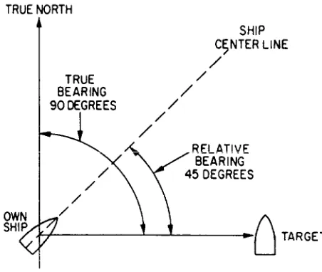
RELATIVE BEARING.— The angle between the
centerline of your own ship or aircraft and a line pointed directly at a target is called the relative bearing of the radar target. This angle is measured in a clockwise direction from the centerline.
Both true and relative bearing angles are illustrated in figure 1-2.
Most surface search radars will provide only range and bearing information. If the operator had a need to direct air traffic or to track incoming missiles, the radar would also have to provide altitude.
Altitude
[image:13.612.48.274.496.687.2]An operator can determine the altitude of a target by adjusting a movable height line on a height indicator to
Figure 1-2.—True and relative bearings.
the point where it bisects the center of the target. The altitude is then displayed by an altitude dial or digital readout. A search radar system that detects altitude as well as range and bearing is called a three-dimensional (3D) radar.
Altitude or height-finding radars use a very narrow beam in the vertical plane. This beam is scanned in elevation, either mechanically or electronically, to pinpoint targets. Tracking and weapons-control radar systems commonly use mechanical elevation scanning techniques. This requires moving the antenna or radiation source mechanically. Most air search radars use electronic elevation scanning techniques. Some older air search radar systems use a mechanical elevation scanning device; however, these are being replaced by electronically-scanned radar systems.
RADAR DETECTING METHODS
Radar systems are normally divided into operational categories based on energy transmission methods. Although the pulse methcd is the most common method of transmitting radar energy, two other methods are sometimes used in special applications. These are the continuous wave (cw) method and the frequency modulation (fm) method.
Continuous Wave
The continuous wave (cw) method uses the Doppler effect to detect the presence and speed of an object moving toward or away from the radar. The system is unable to determine the range of the object or to differentiate between objects that lie in the same direction and are traveling at the same speed. It is usually used by fire control systems to track fast moving targets at close range.
Frequency Modulation
Pulse Modulation
With the pulse modulation method, depending on the type of radar, energy is transmitted in pulses that vary from less than 1 microsecond to 200 microseconds. The time interval between transmission and reception is computed and converted into a visual indication of range in miles or yards. Pulse radar systems can also be modified to use the Doppler effect to detect a moving object. The Navy uses pulse modulation radars to a great extent.
FACTORS AFFECTING RADAR PERFORMANCE
Radar accuracy is a measure of the ability of a radar system to determine the correct range, bearing, and in some cases, altitude of an object. The degree of accuracy is primarily determined by the resolution of the radar system and atmospheric conditions.
Range Resolution
Range resolution is the ability of a radar to resolve between two targets on the same bearing, but at slightly different ranges. The degree of range resolution depends on the width of the transmitted pulse, the types and sizes of targets, and the efficiency of the receiver and indicator.
Bearing Resolution
Bearing, or azimuth, resolution is the ability of a radar system to separate objects at the same range but at slightly different bearings. The degree of bearing resolution depends on radar beamwidth and the range of the targets. The physical size and shape of the antenna determines beamwidth. Two targets at the same range must be separated by at least one beamwidth to be distinguished as two objects.
Earlier in this chapter, we talked about other internal characteristics of radar equipment that affect range performance. But there are also external factors that effect radar performance. Some of those are the skill of the operator; size, composition, angle, and altitude of the target; possible electronic-countermeasure (ECM) activity; readiness of equipment (completed PMS requirements); and weather conditions
Atmospheric Conditions
Several conditions within the atmosphere can have an adverse effect on radar performance. A few of these
are temperature inversion, moisture lapse, water droplets, and dust particles.
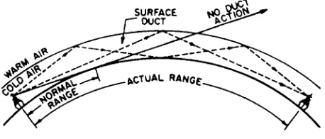
Either temperature inversion or moisture lapse, alone or in combination, can cause a huge change in the refraction index of the lowest few-hundred feet of atmosphere. The result is a greater bending of the radar waves passing through the abnormal condition. The increased bending in such a situation is referred to as
DUCTING, and may greatly affect radar performance.
The radar horizon may be extended or reduced, depending on the direction in which the radar waves are bent. The effect of ducting is illustrated in figure 1-3.
Water droplets and dust particles diffuse radar energy through absorption, reflection, and scattering. This leaves less energy to strike the target so the return echo is smaller. The overall effect is a reduction in usable range. Usable range varies widely with weather conditions. The higher the frequency of the radar system, the more it is affected by weather conditions such as rain or clouds.
All radar systems perform the same basic functions of detection, so, logically, they all have the same basic equipment requirements. Next, we will talk about that basic radar system.
BASIC RADAR SYSTEMS
Radar systems, like other complex electronics systems, are composed of several major subsystems and many individual circuits. Although modern radar systems are quite complicated, you can easily understand their operation by using a basic block diagram of a pulsed radar system.
FUNDAMENTAL RADAR SYSTEM
[image:14.612.334.563.583.681.2]Since most radars used today are some variation of the pulse radar system, the units we discuss in this section will be those used in a pulse radar. All other
types of radars use some variations of these units, and we will explain those variations, as necessary in the next chapter. For now, let’s look at the block diagram in figure 1-4.
Modulator
You can see on the block diagram that the heart of the radar system is the modulator. It generates all the necessary timing pulses (triggers) for use in the radar and associated systems. Its function is to ensure that all subsystems making up the radar system operate in a definite time relationship with each other and that the intervals between pulses, as well as the pulses themselves, are of the proper length.
Transmitter
[image:15.612.73.262.358.677.2]The transmitter generates powerful pulses of electromagnetic energy at precise intervals. The required power is obtained by using a high-power microwave oscillator, such as a magnetron, or a microwave amplifier, such as a klystron, that is supplied by a low-power rf source. (You can review the
Figure 1-4.—Block diagram of fundamental radar system.
construction and operation of microwave components in NEETS module 11, Microwave Principles.)
Duplexer
The duplexer is essentially an electronic switch that permits a radar system to use a single antenna to both transmit and receive. The duplexer must connect the antenna to the transmitter and disconnect the antenna from the receiver for the duration of the transmitted pulse. As we mentioned previously, the switching time is called receiver recovery time, and must be very fast if close-in targets are to be detected.
Antenna System
The antenna system routes the pulse from the transmitter, radiates it in a directional beam, picks up the returning echo and passes it to the receiver with a minimum of loss. The antenna system includes the antenna, transmission lines, and waveguide from the transmitter to the antenna, and transmission lines and waveguide from the antenna to the receiver.
Receiver
The receiver accepts the weak rf echoes from the antenna system and routes them to the indicator as discernible video signals. Because the radar frequencies are very high and difficult to amplify, a superheterodyne receiver is used to convert the echoes to a lower frequency, called the intermediate frequency (IF), which is easier to amplify.
Indicator
The indicator uses the video output of the receiver to produce a visual indication of target information including range and bearing (or in the case of height-finding indicators, range and height).
TYPES OF RADAR SYSTEMS
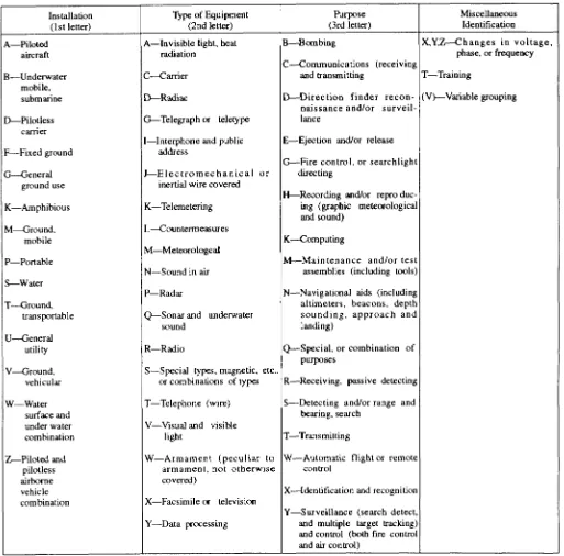
Because of different design parameters, no single radar set can perform all the many radar functions required for military use. The large number of radar systems used by the military has forced the development of a joint-services classification system for accurate identification of radars.
Table 1-1 is a listing of equipment identification indicators. You can use this table and the radar nomenclature to identify the parameters of a particular radar set.
If you use the table to find the parameters of an AN/FPS-35, you will see that it is a fixed (F) radar (P) for detecting and search (S). The AN indicates Army/Navy and the 35 is the model number.
Since no single radar system can fulfill all of the requirements of modern warfare, most modern
warships, aircraft, and shore installations have several radar sets, each performing a specific function. A shipboard radar installation may include surface search and navigation radars, an air search radar, a height-finding radar, and various fire control radars.
Surface Search and Navigation
[image:16.612.64.577.192.698.2]The primary function of a surface search radar is to maintain a 360-degree search for all targets within line-of-sight distance from the radar and to detect and
determine the accurate ranges and bearing of surface targets and low-flying aircraft.
The following are some applications of surface search radars:
Indicate the presence of surface craft and aid in determining their course and speed
Coach fire control radar onto a surface target
Provide security against attack at night, during conditions of poor visibility, or from behind a smoke screen
Aid in scouting
Obtain range and bearing on prominent landmarks and buoys as an aid to piloting, especially at night and in conditions of poor visibility
Facilitate station keeping
Detect low-flying aircraft
Detect certain weather phenomena
Detect submarine periscopes
Aid in the control of small craft during boat and amphibious operations
Navigation radars fall into the same general category as surface search radars. As the name implies, navigation radars are used primarily as an aid to navigate or pilot the ship. This type of radar has a shorter operating range and higher resolution than most surface search radars. Because the navigation and surface search radars share the same general operating characteristics, both radar types can be used simultaneously with one covering longer ranges, while the other covers distances closer to the ship. The use of radars for navigation is discussed further in Electronics
Technician, Volume 5—Navigation.
So now, with surface search and navigation radars on line, the ship is aware of all surface targets, land masses, and low-flying aircraft. But, to protect itself from fighter planes, incoming missiles, and other targets in the upper skies, the ship requires a different type of radar.
Air Search
The primary function of an air search radar is to maintain a 360-degree surveillance from the surface to
high altitudes and to detect and determine ranges and bearings of aircraft targets over relatively large areas.
The following are some applications of air search radar:
Early warning of approaching aircraft and missiles, providing the direction from which an attack could come. This allows time to bring anti-aircraft defenses to the proper degree of readiness and to launch fighters if an air attack is imminent.
Constant observation of movement of enemy aircraft, once detected, to guide combat air patrol (CAP) aircraft to a position suitable for an intercept
Provide security against attacks at night and during times of poor visibility
Provide information used for aircraft control during operations requiring a specific geographic track (such as an anti-submarine barrier or search and rescue pattern)
Together, surface and air search radars provide a good early warning system. However, the ship must be able to determine altitude to effectively intercept any air target. This requires still another type of radar.
Height Finding
The primary function of a height-finding radar (sometimes referred to as a 3D or three-coordinate radar) is to compute accurate ranges, bearings, and altitudes of targets detected by air search radar. This information is used to direct fighter aircraft during interception of air targets.
The height-finding radar is different from the air search radar in that it has a higher transmitting frequency, higher output power, a much narrower vertical beamwidth, and requires a stabilized antenna for altitude accuracy.
The following are some applications of height-finding radar:
Obtain range, bearing, and altitude data on enemy aircraft and missiles to assist in the guidance of CAP aircraft
Provide precise range, bearing, and height information for fast and accurate initial positioning of fire control tracking radars
Determine range to distant land masses
Track aircraft over land
Detect certain weather phenomena
Track weather balloons
As we stated previously, the modern warship has several radars. Each radar is designed to fulfill a particular need, but may be capable of performing other functions. For example, most height-finding radars can be used as secondary air search radars; in emergencies, fire control radars have served as surface search radars.
In this chapter we looked at general radar operation and the three types of radars most frequently maintained by ETs. Tracking radars, missile-guidance radars, and airborne radars are also critical to Navy readiness; however, they are not normally maintained by ETs and will not be covered in this TRAMAN.
CHAPTER 2
RADAR SYSTEMS EQUIPMENT CONFIGURATIONS
In chapter 1, we discussed the configuration of a training, you can become an expert maintainer of ANY basic pulse radar system and the three basic types of
radar sets. We cannot cover in one chapter every radar used by the Navy or every application of radars at the various units. Therefore, this chapter will present only a general overview of commonly used radars. We will not teach you specific equipment, but will help you identify and understand the operation of surface search/navigation radars, air search radars, 3D radars, CCA/GCA radars, and various repeaters used in the Navy today. For each type of radar, we will provide a basic system description, followed by its “theory of operation” and a brief explanation of the maintenance concept.
Most of the radar equipment discussed in this chapter has specific maintenance training available. However, except for certain crypto equipment, you do not need specific training to work on the gear. By combining the information in the appropriate technical manual with your extensive basic electronics background from “A” school and the general knowledge you get through training manuals and on-the-job
electronic equipment.
You’ll be surprised at how much you can figure out on your own. And if you ever get stumped, there are ways to get help. You may request maintenance assistance from tenders, repair ships, Mobile Technical Units (MOTUs), or NAVSEA field activities. In addition, Direct Fleet Support (DFS) will resolve maintenance repair problems beyond the capability of ship’s force, Ship Repair Facilities (SRFs), Intermediate Maintenance Activities (IMAs), and MOTU personnel. If you need DFS assistance, submit a request to the applicable NAVSEACEN via your type commander, as prescribed in NAVSEAINST 4350.6.
The first radars we’ll talk about are the surface search and navigation radars.
SURFACE SEARCH AND NAVIGATION RADARS
surface targets and low-flying aircraft and (2) determine their range and bearing. Some of the more commonly used surface search and navigation radars in the Navy are the AN/SPS-10, AN/SPS-67(V), AN/SPS-64(V)9, and AN/SPS-55. Since the AN/SPS-10 will soon be replaced by the similar AN/SPS-67(V), we will not discuss the AN/SPS-10 in this chapter.
AN/SPS-67
The AN/SPS-67(V) radar is a two-dimensional (azimuth and range) pulsed radar set primarily designed f o r s u r f a c e o p e r a t i o n s . I t c a n a l s o d e t e c t antiship-missiles (ASM) and low-flying aircraft. The AN/SPS-67(V)1 is the primary surface search and navigation radar, with limited air search capability, for the following types of ships:
AO CG DDG LHD
AOE CGN FF LPH
AOR CV LCC LSD
BB CVN LHA TAH
On DDG51 class ships, the AN/SPS-67(V)3 radar performs navigation, station keeping and general s u r f a c e s e a r c h d u t i e s . Additionally, the AN/SPS-67(V)3 supports the combat systems as shown below:
Primary combat mission (ASUW)—provides a quick reaction, automated target detection and track capability
Secondary combat mission (AAW)—detects low elevation (conventional) threats.
General Theory of Operation
The AN/SPS-67(V) radar set operates in the 5450-to 5825-MHz frequency range, using a coaxial magnetron as the transmitter output tube. To enhance radar performance for specific operational or tactical situations, the receiver-transmitter can operate in a long (1.0 %sec), medium (0.25 %sec), or short (0.10 %sec) pulse mode. The corresponding pulse repetition frequencies (prf) are 750, 1200, and 2400.
The AN/SPS-67(V)3 version has a new, high data rate, nuclear survivable, low-profile antenna and pedestal assembly that replaces the AN/SPS-10 antenna and pedestal assembly. In addition, the synchro signal amplifier function is integrated into the radar.
Some special operating features included in the AN/SPS-67(V) radars areas follows:
Automatic Frequency Control (AFC)
Automatic tuning
Fast Time Constant (FTC)
Interference Suppression (IS)
Anti-log circuit (Target Enhance)
Sensitivity Time Control (STC)
Video Clutter Suppression (VCS)
Built-In-Test (BIT) Equipment
Sector Radiate (SR)
Ships Heading Marker (SHM)
Jitter mode
Stagger mode
The following additional special operating functions are included in the AN/SPS-67(V)3 model:
Synthesized Channel Frequency Selection
RF Sensitivity Time Control (RFSTC)
Antenna bearing squint correction
Digital relative to true bearing conversion
Full-time relative and true bearing synchro output at the ante ma controller
Relative or true bearing synchro output selectable at the Radar Set Control (RSC) for the video processor unit
Digital Moving Target Indicator (DMTI)
Selectable environmental sector
Constant False Alarm Rate (CFAR) threshold gating by external control
Centroid function
Track function
Coherent EMI suppression in the DMTI channel
Jam strobe detection
Wraparound test by external control
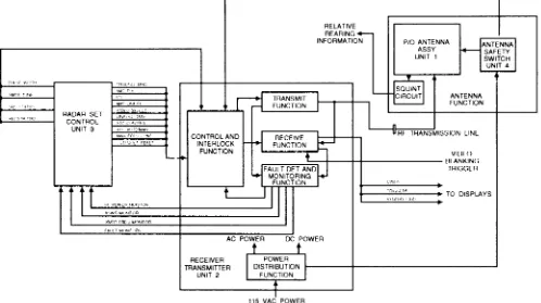
Configuration
The major units of the AN/SPS-67(V)1 and (V)3 radar sets are shown in figure 2-1 and figure 2-2 respectively. As you can see, there is only a slight difference between the AN/SPS-67(V)1 and the AWSPS-67(V)3 versions. Think back to the basic block diagram of a pulse radar in chapter 1 (fig. 1-4). Relate the function blocks in figure 1-4 to the basic units shown in figure 2-1. If you understand the basics, you’ll find that no matter how many special operating functions a radar has, the basic system is still the same.
The receiver-transmitter and video processor components of the AWSPS-67(V) bolt to the same bulkhead foundations used for the AN/SPS-10 series components. The remaining components mount in the same area of the units they replace, although they may or may not have the same shape as the AN/SPS-10 components. The dummy load mounts on the output of the receiver-transmitter unit.
SIGNIFICANT INTERFACES.— Although
radar systems provide valuable information by themselves, the interface of that information with other warfare systems is critical.
The AN/SPS-67(V)1 meets interface requirements of the following equipment:
Electronic Synchronizer, AN/SPA-42 or AN/SPG-55B
Blanker-Video Mixer Group, AN/SLA-10( )
IFF Equipment
Indicator Group, AN/SPA-25( ) or equivalent
Synchro Signal Amplifier, Mk 31 Mod 8A or equivalent
The AN/SPS-67(V)3 meets interface requirements for the following additional equipment:
Shipboard Emission Monitor-Control Set, AN/SSQ-82(V) (MUTE)
Data Multiplex System, AN/USQ-82(V)
Signal P r o c e s s o r C o n v e r t e r G r o u p , OL-191(V)5/UYQ-21(V)
Command and Decision System, Mk-2
Gyro Digital Converter, P/O Mk-38/39 and ACTS Mk-29
Surveillance and Control System, AN/SPY-1
FOR THE MAINTAINER.— The AF/SPS-67(V) is
a solid-state replacement for the AN/SPS-10 radar system. Miniature and micro-miniature technologies are used throughout the radar set. It is more reliable and has better logistical support, with 92 percent of its construction being Standard Electronic Modules (SEM).
The Built-in-Test (BIT) microprocessor sub-assembly uses on-line performance sensors to decrease the chance of operating the radar with an undetected fault. Using BIT circuitry during normal operation will not degrade system performance, nor will faulty BIT circuitry affect system performance. When system failures do occur, you can use BIT to isolate 95 percent of the possible faults to a maximum of four modules within the receiver-transmitter or video processor.
BIT circuitry uses light-emitting diodes (index indicators) at certain test points to indicate the locations of faults. The condition of the system at each test point is displayed on readout indicators as GO, MARGINAL, or NO-GO. In addition, the BIT subsystem provides an interactive test mode that permits you to monitor certain test points while making level or timing event adjustments. Power and voltage standing wave ratio (vswr) are monitored on an on-line basis. The BIT subsystem also automatically tests itself periodically by going into a self-check mode.
Maintenance
The AN/SPS-67(V) radar set operates continuously during the ship’s deployment. The responsibility for the organizational level maintenance falls on the ship’s Electronics Technicians, (NEC ET-1507.)
Organizational level maintenance consists of preventive maintenance (PM) and corrective maintenance (CM). PM is performed according to maintenance requirement cards (MRCs) developed for the AN/SPS-67(V) system. PM at this level includes checks of operational status and filter/equipment cleaning. CM is performed according to the AN/SPS-67(V) technical manual procedures, and includes removing and replacing chassis-mounted piece parts, modules, assemblies, and sub-assemblies.
R e p a i r a b l e m o d u l e s , a s s e m b l i e s , a n d sub-assemblies are returned to the depot according to Navy supply procedures.
AN/SPS-64(V)9
Figure 2-1.—AN/SPS-67(V)1 radar.
ships. It is also used as a back-up radar on large combatants. It provides a true bearing display for coastal piloting and a capability for radar navigation and station keeping.
The AN/SPS replaces a variety of small commercial radars on the following types of ships:
AE ASR C G N F F G LPH
AGDS ATS CV LCC LST
A O E A V T CVN LHA MHC
ARL BB DDG LHD MSO
ARS CG FF LPD PHM
General Theory of Operation
The AN/SPS-64(V)9 has a minimum detection range of 20 yards on a radar cross-sectional target of 10 square meters, 3 feet above the surface of the water. It can operate in either true or relative bearing when used with Navy gyrocompasses.
Some special operating features of the radar include:
Ship line voltage protection
Ship Heading Marker (SHM)
Variable range marker
Configuration
Figure 2-3 provides a general overview of how this radar operates. Unlike the AN/SPS-67 radars, this off-the-shelf radar system was not designed to use existing antennas and indicators. All the components, including the indicator and the antenna system, are unique to the AN/SPS-64(V)9.
SIGNIFICANT INTERFACES.— Information
from the AN/SPS-64(V)9 interfaces with the following Navy equipment:
Blanker/Video Mixer Group, AN/SLA-10
Indicator Group, AN/SPA-25( ) or equivalent
Synchro Signal Amplifier, Mk 27 or equivalent
Mk 19 gyrocompass or equivalent
FOR THE MAINTAINER.— The
[image:23.612.66.534.393.680.2]AN/SPS-64(V)9 is designed and constructed according to the best
commercial practices. For example, there are safety i n t e r l o c k s o n t h e a n t e n n a p e d e s t a l , t h e receiver/transmitter (R/T) unit, and the azimuth range indicator. All the other units include ON/OFF switches and indicator lights.
Maintenance
The AN/SPS-64(V)9 was purchased as the single, commercially available, off-the-shelf radar for the Navy’s Class B1 radar program. Maintenance support, including documentation, spares, and levels of maintenance is also an off-the-shelf concept.
Maintenance responsibilities are assigned to an existing billet and performed by an Electronics Technician (no specific NEC assigned). Organizational level maintenance consists of preventive maintenance (PM) and corrective maintenance (CM). PM is done according to the maintenance requirement cards (MRCs). CM consists of (1) adjustments, alignments, and tests, as described in the technical manual and (2) replacement of the lowest replaceable unit (LRU) required to correct radar discrepancies.
The Miniature/Microminiature (2-M) Electronic Repair Program and the Support and Test Equipment Engineering Program (STEEP) are not used for the AN/SPS-64(V)9 radar, since the Navy has no data rights for the equipment.
M a j o r o v e r h a u l a n d r e s t o r a t i o n o f t h e AN/SPS-64(V)9 radar and LRU repair are performed at the depot level, in the prime contractor’s facility. Technical Repair Standards (TRSs) are not available since the Navy does not make depot-level repairs.
AN/SPS-55
The AN/SPS-55 is a solid-state, Class A surface search and navigation radar. It is used to detect small surface targets and for navigation and pilotage. The AN/SPS-55 radar detects targets from as close as 50 yards to as far as 50 nautical miles. It was specifically d e s i g n e d f o r i n s t a l l a t i o n i n t h e f o l l o w i n g new-construction ship classes:
AO-177 CGN-38 DDG-993 MCM-1
CG-47 DD-963 FFG-7 PBC-1
A radar video converter (RVC) modification was developed for AN/SPS-55s used on the FFG-61 class.
The AN/SPS-55 radar supports several mission areas including Antisurface Warfare (ASUW), Antisubmarine Warfare (ASW), Amphibious Warfare (AMW), Special Warfare (SPW), Mobility (MOB), and Command and Control (CAC).
General Theory of Operation
The radar set operates from 9.05 GHz to 10 GHz, and can tune over the entire bandwidth within 60 seconds. Tuning can be controlled from either the remote radar set control (RSC) or the receiver-transmitter (R/T) unit. The transmitter uses a magnetron with a minimum peak power of 130 KW. The receiver can operate in a long-pulse mode (1.0 %sec) or short-pulse mode (.12 %sec) with minimum ranges of 200 yards and 50 yards respectively. The antenna consists of two back-to-back end-fed, slotted waveguide arrays with a scan rate of 16 rotations per minute (rpm).
Some special operating features of the AN/SPS-55 radar set include:
Squint compensation
Variable sensitivity time control
Fast time constant (FTC)
Log/linear-log intermediate frequency (IF) amplifier
Video blanking circuit
Sector radiate capability
Automatic and manual frequency control (AFC/MFC)
The RVC modification provides these additional features:
Analog/digital (A/D) conversion
Digital integration with beam time interval
Noncoherent DMTI
Moving window constant false alarm rate (CFAR) thresholding
Segmented CFAR
Configuration
Figure 2-4.—AN/SPS-55 block diagram.
receiver-transmitter (R/T), the radar set control (RSC), and the antenna safety switch.
Although the AN/SPS-55 radar is electronically reliable, the antenna pedestal has been a source of mechanical maintenance problems. A field change kit, developed in FY89, provided an improved antenna pedestal. Delivery and installation of the pedestal modification are coordinated by the Restoration Program Manager.
SIGNIFICANT INTERFACES.— The
AN/SPS-55, like all radars, has an impact on other systems, subsystems, and equipment. The RVC modification developed for the FFG-61 and the antenna pedestal modification not only improved the radar set, but improved the interface capabilities. The RVC enables the FFG-61 Integrated Automatic Detection and Tracking System (IADT) to use the AN/SPS-55 data. The pedestal modification allows interface with IFF.
The AN/SPS-55 interfaces with the following equipment:
Blanker/Video Mixer Group, AN/SLA-10
Indicator Group, AN/SPA-25( ) or equivalent
Mk 27 synchro signal amplifier or equivalent
Mk XII IFF (pedestal mod only)
AN/SYS-2(V)2 IADT (FFG-61 RVC mod only)
FOR THE MAINTAINER.— The AN/SPS-55
radar has various built-in features to protect the maintainer and the equipment. The transmitter has a voltage standing wave ratio (vswr) alarm. Fault detection indicators, located on both the transmitter and the RSC unit, show when the high-voltage power supply, modulator, or magnetron exceeds predetermined safe limits. A low-power condition in the radar automatically places the radar in the standby mode and activates an indicator at the RSC when low power exists.
The antenna safety switch, when activated, opens the radiate interlock, removing power from the drive motor. It also activates a “Man Aloft” indicator on both the R/T and the RSC unit to ensure that no one tries to operate the radar during maintenance.
Maintenance
lowest replaceable unit (LRU). The technical manual lists the assemblies and components that can be replaced during organizational level maintenance.
Electronics Technicians (NEC ET-1491 for FFG-7 Class ships or ET-1504 for all other ships) are responsible for organizational level maintenance of the AN/SPS-55. Preventive maintenance (PM) and corrective maintenance (CM) include:
electrical and mechanical alignments;
adjustments, and calibration;
fault detection, isolation, and module or major part repair/replacement; and
all correction and verification necessary to restore the radar set to an operating condition.
Disposition and repair of failed components is specified by the Source, Maintenance, and Recoverability (SM&R) codes in the applicable Allowance Parts List (APL). Send your repairable modules to the Designated Overhaul Point (DOP) for repair or condemnation.
AIR SEARCH (2D) RADARS
The two primary functions of air search radar are to (1) detect aircraft targets at long ranges and (2) determine their range and bearing. Some of the most widely used two-dimensional (2D) air search radars in the Navy are the AN/SPS-37A, AN/SPS-43, AN/SPS-43A, AN/SPS-49(V), AN/SPS-40B/C/D/E, and AN/SPS-65(V) aboard ships and the AN/GPN-27 (ASR) at shore installations.
We will not discuss the AN/SPS-29, AN/SPS-37, and AN/SPS-43 radars, since the AN/SPS-49(V) radar replaces them.
AN/SPS-49(V)
The AN/SPS-49(V) radar is the primary U.S. Navy early warning air search 2D radar. It is a very-long-range radar, and provides long-range air surveillance in severe clutter and jamming environments. It primarily supports the anti air warfare (AAW) mission on surface ships, but also provides backup to the 3D weapon system radar. The AN/SPS-49(V) radar is also used for air traffic control (ATC), air intercept control (AIC), and antisubmarine aircraft control (ASAC).
The AN/SPS-49(V) radar replaces the AN/SPS-29, AN/SPS-37, AN/SPS-40, and AN/SPS-43 radars in some ships, including the following ship types:
CG CV DDG LHD
CGN CVN FFG LSD
Current planning calls for installation of the AN/SPS-49(V) radar in 160 U.S. Navy ships, plus various shore installations.
General Theory of Operation
The AN/SPS-49(V) is a narrow-fan beam radar developed from a Specific Operational Requirement. It provides the capability to conduct air search operations on a previously unused radar frequency. This minimizes electronic interference between ships and increases the difficulty for hostile electronic countermeasures (ECM). The AN/SPS-49(V) provides good bearing measurements to backup the 3D radar weapons system. Its narrow beamwidth substantially improves resistance to jamming.
The coherent side lobe canceler (CSLC) cancels jamming and interference signals, providing the AN/SPS-49(V) radar further resistance to jamming and interference. The DMTI capability enhances detection of low-flying, high-speed targets.
The AN/SPS-49(V)5 version, which has automatic target detection (ATD) capability, has even more sophisticated antijamming features. This version offers improved clutter suppression and a digital interface to the AN/SYS-2(V) IADT system. The AN/SPS-49(V)5, does not cancel non-moving targets as with MTI, instead it uses the newest development in doppler processing, Finite Impulse Response (FIR) fibers. These filters separate radar echo returns into fixed and moving channels according to their doppler characteristics. The moving channels contain moving targets only. The fixed channels contain fixed clutter and blind speed targets. Rejection of non-moving targets recurs at a later point in time in the clutter maps.
The “AEGIS Tracker” modification consists of a PCB card set integrated into the signal data processor. It adds an embedded tracker, with direct digital interface with the AEGIS combat system, to the AN/SPS-49(V)7 radar (installed on AEGIS cruisers). With this modification incorporated, the AN/SPS-49(V)7 nomenclature changes to AN/SPS-49(V)8.
It improves performance against small targets when subjected to stand-off jamming. The modification primarily replaces the receiver’s sensitivity time control (STC) with a sensitivity velocity control (SVC). SVC uses radial velocity and target size information to “filter” out birds and near-in clutter. It suppresses these unwanted targets while retaining detection performance throughout the volume of coverage. The MPU also aids in reducing reaction time to only two scans by providing very high-quality velocity estimates for radar targets.
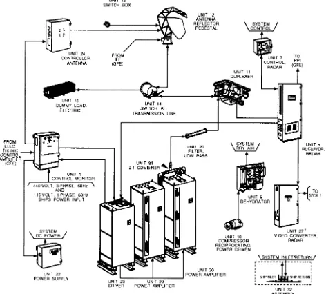
Configuration
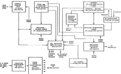
The AN/SPS49(V) radar set contains 47 major units in nine variant configurations, (V)1 through (V)9. Figure 2-5 shows the physical configuration of the AN/SPS-49(V) radar system.
The nine variant configurations are:
(V)1 Baseline radar
(V)2 AN/SPS49(V)1 radar without the coherent side lobe cancellation feature
(V)3 AN/SPS-49(V)1 radar with the radar video processor (RVP) interface (FC-1)
(V)4 AN/SPS49(V)2 with the RVP interface
(V)5 AN/SPS-49(V)1 with automatic target detection (ATD)
(V)6 AN/SPS-49(V)3 without the cooling system
(V)7 AN/SPS-49(V)5 without the cooling system
(V)8 AN/SPS-49(V)7 with automatic detection and tracking (ADT)
(V)9 AN/SPS-49(V)5 with medium PRF upgrade (MPU)
SIGNIFICANT INTERFACES.— The
AN/SPS-49(V) radar interfaces with shipboard display systems via conventional radar switchboards and NTDS switchboards. Field Change 1 provides an optional interface through the Dual Channel RVP and associated equipment. In addition, the AN/SPS-49(V)5 version interfaces with the AN/SYS-2(V) MDT system.
FOR THE MAINTAINER.— Solid-state
tech-nology with modular construction is used throughout the radar, except for the klystron power amplifier and high-power modulator tubes. Digital processing
techniques are used extensively in the AN/SPS-49(V)5, 7 and 8.
The radar has comprehensive BIT features, such as performance monitors, automatic fault detectors, and built-in-test equipment (BITE). The AN/SPS-49(V)5, 7, and 8 include automatic, on-line, self-test features. Each major unit has test panels with fault indicators and test points. There is also a test meter to monitor system power supply voltage.
Maintenance
The AN/SPS-49(V) radar operates continuously during deployment. Radar maintenance is a responsibility of the ET rating (NEC ET-1503 for (V)1, 2, 3, 4, and 6 or ET-1510 for (V)5, 7, 8 and 9). Basic maintenance involves module replacement and planned maintenance (PM) and follows the policies s e t f o r t h i n N A V S E A I N S T 4 7 0 0 , 1 a n d NAVMATINST 4700.4B.
Organizational maintenance consists of PM and CM, performed on the radar in place, while the ship is underway. CM is limited to (1) fault isolation, (2) removal and replacement of modules or cabinet-mounted piece parts, and (3) the adjustment, alignment, and testing required to correct the radar degradations. All repairable modules are shipped to DOP for repair as directed by SPCC Mechanicsburg.
Removing and replacing the radar antenna and various major antenna subassemblies require intermediate-level maintenance. These tasks are conducted as directed by the NAVSEASYSCOM Restoration Program.
AN/SPS-40B/C/D/E
The AN/SPS-40B/C/D/E is the primary shipboard long-range, high-powered, two-dimensional (2D), air search radar. It provides 10-channel operation, moving target indicator (mti), pulse compression, and high data short range mode (SRM) for detecting small, low-altitude, close-in targets. Designed for use aboard frigate-size or larger ships, the AN/SPS-40B/C/D radar is used on the following types of ships:
AVT FF CC CGN DDG
Field Change 11, which changes the nomenclature to AN/SPS-40E, replaces the tube-type power amplifier with a solid-state transmitter (SSTX) and provides a substantial improvement in operational availability. The AN/SPS-40E radar is used on the following types of ships:
AGF DD LHA LPH
The many changes to this radar set have improved its minimum range capability, as well as made it more reliable and easier to maintain.
General Theory of Operation
The AN/SPS-40 radar set, with the automation module, is better able to detect targets over land and water and to generate clutter-free target data. It has a two-speed drive motor, which increases the antenna rate to 15 rpm for high-data rate capabilities and operates at a normal 7.5 rpm speed in the long-range mode (LRM).
Some special operating features of the AN/SPS-40B/C/D/E include the following:
DMTI
Long-range, long-range/chaff, and short-range modes
Automatic target detection (ATD)
Built-in-test (BIT) equipment
Analog/digital conversion
Four-pulse staggered pulse repetition frequency (prf)
Operator selectable antenna scan rate
Sensitivity time control (STC)
Configuration
Figure 2-6 illustrates the AN/SPS-40B/C/D DMTI/RVC radar system. The DMTI field change replaces the analog moving target indicator with more reliable and more easily maintained digital circuitry. It also provides a new radar set control (RSC) and replaces the duplexer with a solid-state unit. The RVC field change allows the radar to interface with the AN/SYS-1 IADT system.
Installation of the solid-state transmitter, field change (FC-11 ), replaces 11 shipboard units (units 2, 3, 4, 6, 16, 17, 18, 19, 21, 23, and 25) with five units (units 28 through 32) as shown in figure 2-7.
SIGNIFICANT FIELD CHANGES.— As we
mentioned before, this radar set has had many changes. Some of the more significant field changes are:
Digital moving target indicator (DMTI)—solid-state upgrade
Radar video converter (RVC)—interface with AN/SYS-1
Solid-state transmitter (SSTX)—changes the number of units in the configuration and the nomenclature of the system
AN/SPS-40E Field Change 2—changes the two-cabinet PA configuration to a single cabinet PA
AN/SPS-40E Field Change 3—replaces the DMTI with a new coherent receiver processor
SIGNIFICANT INTERFACES.— The
An/SPS-40B/C/D/E interfaces with shipboard display systems via conventional radar switchboards and NTDS switchboards. The AN/SPS-40B/C/D/E radar with DMTI/RVC interfaces with the AN/SYS-1 Integrated Automatic Detection and Tracking System (IADT).
FOR THE MAINTAINER.— The increased use of
solid-state design and modular construction in the AN/SPS-40 radar results in a longer mean time between failures (MTBF) and a shorter mean time to repair (MTTR). The new receiver and mti both use built-in-test equipment to help in alignment and troubleshooting.
Maintenance
The AN/SPS-40B/C/D/E radar is designed for continuous operation during deployment. The maintenance responsibilities are assigned to the ET rating (NEC ET-1516, ET-1508 (with DMTI), and ET-1511 (with FC-11)). The SPS-40’s modular design minimizes maintenance actions at the organizational level.
Organizational maintenance includes preventive and corrective maintenance. PM is performed according to technical manuals and maintenance requirement cards (MRCs).
CM is performed according to the corrective maintenance section of the technical manuals and by the Source Maintainability and Recovery (SM&R) code assigned in the APL. You may be required to perform any of the following actions:
Remove and replace cabinet-mounted piece parts, modules, assemblies or sub-assemblies.
Repair modules, assemblies, or sub-assemblies designated as shipboard repairable.
Figure 2-7.—AN/SPS-40E radar system.
System overhaul and restoration are performed on AN/GPN-27 (ASR-8)
a turn-around basis every 10-15 years by naval
General Theory of Operation
The AN/GPN-27 is a modular, solid-state, dual-channel, dual-beam/frequency diversity, S-band, surveillance radar used for safe, efficient movement of air traffic within the naval or Marine Corps Air Station National Airspace System area.
Some of the operating features include:
Stable local oscillator (STALO)
MTI with 10-bit design
Clutter rejection
Circular polarization
Reduced side lobes
Field-programmable range azimuth gate
Configuration
The AN/GPN-27 radar includes three major groups: an antenna group, a transmitter building group, and a display site group.
The antenna group consists of a reflector, dual-feed assembly, rotary joint, pedestal, and a dual-drive train assembly. It is a dual-beam design with normal and passive channels, including switchable linear and circular polarization. The cosecant-squared elevation pattern provides constant radiation altitude coverage up to 30 degrees above peak of beam. The passive, receiver-only feed horn is tilted upward from the normal beam to reduce interference from ground clutter at short ranges.
In the transmitter building group, the transmitter has an air-cooled klystron, a solid-state modularized modulator, and a solid-state, high-voltage power supply. The receiver provides normal video, log video, and moving target indicator (mti) video signals to the processor unit. The digital processor processes the receiver video for the radar tuning and control circuits, the range/azimuth gate generator, the azimuth pulse generator (APG), and the video cable-line drivers. The system control interface and distribution unit features a solid-state control system for radar command and status indications. A 16-inch maintenance plan position indicator (MPPI) aids in system alignment and maintenance. The transmitter building group also has two of the five stations (1 master and 1 slave) of the intercommunication system.
The display site group at the indicator site or air traffic control (ATC) room consists of a display site remote unit, two system control panels, a display site cable junction box, and an intercommunications system with three stations (2 master and 1 slave).
SIGNIFICANT INTERFACES.— The only
interfacing is within the system itself. The control system contains control boxes that have release and take-control circuitry to ensure that radar command is available only at the selected control box. Operators scan the radar screen for incoming and outgoing aircraft, vector aircraft to the airfield, and work with other controllers to coordinate precision approach radars (PAR) and land aircraft.
FOR THE MAINTAINER.— The AN/GPN-27
uses state-of-the-art design and technology. All radar command and status signals stay in power-protected solid-state memory, isolating the control system from short-term power outages. The MPPI at the transmitter building aids in system alignment and other maintenance.
Maintenance
Maintenance of the AN/GPN-27 is performed on demand or as scheduled and is done by Electronics Technicians (NEC ET-1580). Organizational level maintenance includes fault isolation, performance testing, and alignment. Corrective maintenance consists of the removal and replacement of sub-assemblies, modules, and printed circuit boards ( P C B s ) . Those items not repairable at the organizational level are returned to the depot facility through normal Navy supply channels.
THREE COORDINATE (3D) AIR SEARCH RADARS
Fire Control Technicians (FCs) usually maintain the height-finding radars installed aboard Navy ships. So, rather than cover specific equipment, we will cover general information to help you understand the overall radar capabilities of your ship.
control it manually for searching in a specific target sector.
As we mentioned in chapter 1, the air search 3D radars determine altitude by scanning the vertical plane in discrete increments (steps). Although this may be done mechanically, most frequently, it is done electronically. Figure 2-8 shows the radar beam radiated at different elevation angles as electronic scanning changes the radiated frequency in discrete steps. Each elevation angle or step has its own particular scan frequency.
A computer electronically synchronizes each radiated frequency with its associated scan angle to produce the vertical height of a given target.
The 3D radars also use a range-height indicator (RHI) in addition to the PPI used with 2D radars. We will discuss both indicators in further detail in the section on radar indicators.
CARRIER-CONTROLLED APPROACH (CCA) AND GROUND-CONTROLLED
APPROACH (GCA) RADARS
C a r r i e r - c o n t r o l l e d a p p r o a c h ( C C A ) a n d ground-controlled approach (GCA) systems guide aircraft to safe landings, even under conditions approaching zero visibility. Radar is used to detect aircraft and to observe them during their final approach and landing. Guidance information is supplied to the pilot in the form of verbal radio instructions, or to the automatic pilot (autopilot) in the form of pulsed control signals.
The primary approach systems in the Navy are the AN/SPS-46(V) Precision Approach Landing System (PALS) for CCA and the AN/FPN-63 Precision Approach Radar (PAR) for CGA.
AN/SPN-46(V) PALS
[image:33.612.50.281.613.681.2]The AN/SPN-46(V)1 system provides safe and reliable final approach and landing for PALS-equipped
Figure 2-8.—Electronic elevation scan.
carrier-based aircraft, during daylight or darkness. It is rarely affected by severe weather and sea state conditions, and is not affected by low ceiling and visibility problems.
The AN/SPN-46(V)2 system is installed at selected naval air stations (NAS). It is used for the PALS training of flight crews, operator and maintenance personnel, and the PALS certification of aircraft.
The AN/SPN-46(V)1 system replaces the AN/SPN-42A Automatic Carrier Landing System (ACLS) on CV/CVN class ships. The AN/SPN-46(V)2 system replaces the AN/SPN-42T1/3/4 at various naval air stations.
General Theory of Operation
The AN/SPN-46(V) PALS allows simultaneous and automatic control of two aircraft during the final approach and landing phase of carrier recovery operations. Designed primarily as an “automatic” landing system, it also has manual control capabilities. The AN/SPN-46(V) has three modes of operation that are identified, based on the type of control (automatic or manual) and the source of information (display or voice).
Mode I (automatic control).—The Central
Computer Subsystem (CCS) processes flight information from the radar/ship motion sensor (SMS), wind speed and direction equipment, and other ancillary equipment. It then transmits command and error signals to each aircraft via the Link 4A. The aircraft receives these command and error signals and translates them into control actions that maintain the aircraft within a narrowly prescribed flight envelope.
Mode II (manual control with display).—The
aircraft cockpit display receives command and error signals that direct the pilot to take proper actions.
Mode III (manual control with voice).—The air
traffic controller, using the processed flight data transmitted to the operator control console (OCC), provides the pilot with voice communications for a manual approach.
Configuration