ISSN Online: 2164-0181 ISSN Print: 2164-0165
DOI: 10.4236/mme.2017.73006 Aug. 31, 2017 73 Modern Mechanical Engineering
Structural Design via Genetic Optimization
David Webb1, Wissam Alobaidi2*, Eric Sandgren2*
1Axalta Coating Systems, Front Royal, USA
2Systems Engineering Department, Donaghey College of Engineering & Information Technology, University of Arkansas at Little
Rock, Little Rock, USA
Abstract
Structural designs (i.e. truss structures) are derived by the use of a three phase genetic optimization approach, where the minimization of volume is the ob-jective of each truss structure considered. A genetic algorithm is employed which controls the three phase optimization technique. The first phase utilizes the conventional functionality of the genetic algorithm from an evolutionary perspective, however designer interaction by the use of constant rules is pro-vided to ensure an effective evolutionary search outcome. The second phase enhances the best design constructed from phase one by the use of domain specific knowledge in the form of design rules. Phase three improves the final design assembled within phase two by the reduction of truss element areas. This refinement process ensures that the design constraints provided are ac-tive, indicating an optimal search solution. All phases operate from a global perspective; however the phase two optimization methodology operates from a more radical approach which encompasses the concept of designing from a “blank sheet of paper” point of view. Results are provided upon the conclu-sion of each truss example considered which includes the outcomes of each phase for comparison purposes.
Keywords
Structural Optimization, Genetic Optimization
1. Introduction
Truss optimization has been approached using a wide variety of optimization techniques to optimize a realm of diverse truss structures which encompass vast applications. These techniques involve cross sectional and geometry optimiza-tion through sequential quadratic programming demonstrated by Smith, Hod-gins, Oppenheim, and Witkin [1] which include roof trusses and the Eiffel How to cite this paper: Webb, D.,
Alobai-di, W. and Sandgren, E. (2017) Structural Design via Genetic Optimization. Modern Mechanical Engineering, 7, 73-90. https://doi.org/10.4236/mme.2017.73006
Received: August 12, 2017 Accepted: August 28, 2017 Published: August 31, 2017
Copyright © 2017 by authors and Scientific Research Publishing Inc. This work is licensed under the Creative Commons Attribution International License (CC BY 4.0).
DOI: 10.4236/mme.2017.73006 74 Modern Mechanical Engineering Tower. Comparison studies between genetic algorithms and a “Modified Reac-tive Taboo Search” have been established through N-shaped roof trusses by Hamza, Mahmoud, and Saitou [2]. Additionally the robust character of a con-ventional ten bar truss has been investigated through cross sectional, geometric, and topological design changes via a genetic algorithm evolutionary search pro-vided by Sandgren and Cameron [3]. Furthermore, the Michell Truss has been investigated by Kepler [4], where the fundamental principles which define the uniqueness of the truss can be found within a human thighbone on a micro-scopic level. Kepler [4] also explores the trellis truss among a variety of practical applications from early Eskimo kayaks, rally-cars, transmission towers, and mo-torcycle frame design. A more advanced application involving robotic move-ment among truss members which support a space solar power satellite trans-mitter array is provided by Leger [5].
Many truss optimization techniques may be captured within the structure of a conventional genetic algorithm where a global and effective search can be uti-lized. However, a conventional genetic algorithm operation has many limitations including:
1) Genetic input parameters are application specific
2) The initial population, which is randomly generated, has a significant im-pact on all offspring created
3) Mutation must be relied upon in order to achieve a global solution
4) Problems of increased complexity require extensive computational time for an adequate global solution
5) Global search solutions generally require user modification before the solu-tion is located which satisfies the general purpose of the intended applicasolu-tion
These hurdles are primarily attributed to the encoding or chromosome string of a conventional genetic algorithm. This chromosome string is a representation of the design where each value within the string correlates to a specific characte-ristic or trait associated with the investigated design.
The conventional genetic algorithm begins by generating an initial random population of chromosome strings. Each chromosome string value is applied to each truss element and the newly generated design is solved by a finite element routine where local parameters are calculated. Objective function and predeter-mined constraints based upon calculated local parameters and overall volume reduction are employed to reveal which strings are best suited to become parent strings. Subsequent to objective and constraint function evaluation, the fitness value of a string is assigned exclusively by the objective function, if and only if the individual string fails to violate any constraints. Design strings which possess failing constraint values are assigned fitness values determined by a penalty function. The overall value of the design is determined by the penalty function introduced by Equation (1).
( )
( )
{
( )
}
2– i i
P x = f x RΣ g x (1)
DOI: 10.4236/mme.2017.73006 75 Modern Mechanical Engineering i = 1,∙∙∙, number of constraints
where
( )
{
gi x}
=0; for g xi( )
≥0( )
{
gi x}
=gi( )
x ; for g xi( )
<0The value f(x) or the objective function is incorporated to further reward or penalize the design by the total amount of what is to be maximized or mini-mized. The purpose of the penalty function R is to penalize designs analyzed which fail to meet important design limits where the initial value of R presented is 10. This penalty factor is user specified and increases by a constant numeric value once a specified number of generations have been produced which consists of a numerical value of 2. The inclusion of the number of the constraint function gi(x) is necessary to provide numerically how much the design has failed to meet
the set of individual constraints. The overall fitness value is a reflection of the design, and due to the formulation of the penalty function, poor designs are eventually removed from the genetic process. The best strings are gathered into a “mating pool” where the genetic algorithm randomly selects chromosome strings to mate with one another. Chromosome characteristics are exchanged within each parent design string and offspring chromosome strings are pro-duced. Special operators such as mutation are introduced to inject alternative designs to further enhance the evolutionary optimization process especially when utilizing a relatively small population size. For this study, the probability of mutation factor was set at 0.01. Ultimately the genetic algorithm relies on the randomness present in the initial gene pool, but quickly exploits information gathered in order to produce an efficient optimization. Goldberg [6] and Davis [7] discuss genetic algorithms in further detail. This genetic optimization pro-cedure stimulates the need to improve the global nature of the search where a novel second phase approach is introduced by providing designer knowledge in the form of decision based rules. This second phase alters the fundamental chromosome string to a series of rule sequences to be executed based upon do-main specific knowledge which either eliminates or significantly reduces the problems associated with the functionality of the traditional genetic algorithm.
2. Background
DOI: 10.4236/mme.2017.73006 76 Modern Mechanical Engineering The phase one optimization methodology operates by the use of an evolutio-nary approach; however constant rules are introduced which ensures structural integrity among all offspring developed throughout the global search. This evo-lutionary approach generates truss structures which require the minimum amount of elements to sustain loading and constraint conditions. Additionally, the modulus of elasticity of elements throughout the optimization procedure is manipulated to allow for an assortment of materials to be present in the con-struction of a final phase one design. However, due to the formulation of local element stiffness matrices, element lengths, areas, and modulus of elasticity val-ues are considered constants where a change in modulus of elasticity value may be interpreted as a change in area rather than material property.
The phase two optimization methodology refined the best phase one design from a “blank sheet of paper” point of view, where force and ground nodes are the only required constant nodal locations. Phase two manipulates element areas, nodal coordinates, removes existing nodes, and creates elements which are initially nonexistent. Structural integrity is maintained throughout the optimiza-tion procedure by the implementaoptimiza-tion of a finite element solver which calculates element stress and nodal displacement. Additional constraints which aid the phase two optimization procedure are element length, area, and nodal coordi-nate constraints.
Phase three refines the best design generated from phase two which utilizes the traditional genetic algorithm methodology. Each element within the final phase two design is subjected to area reduction to effectively produce active con-straint values (i.e. gi(x) ≈ 0) indicating that an optimal solution has been located.
A primary function of phases one and two is to generate the optimal topology of a truss structure, where any further removal of elements results in either a sin-gular matrix or constraint violating solution. Phase two possesses the capability of reducing truss element areas; however phase three provides a more rigorous approach to refine the most optimal topological design.
3. Problem Formulation
DOI: 10.4236/mme.2017.73006 77 Modern Mechanical Engineering where a predetermined range of values which consist of 0.1 to 1 with a step size of 0.01 are assigned to each chromosome to potentially reduce element areas and ultimately the overall volume of the structure.
Domain specific knowledge is introduced into the genetic algorithm global search solution in the form of decision based rules. This rule based approach al-ters the encoding strings of the conventional genetic algorithm. Each string is composed of chromosomes of which select and provide additional information to execute specified rules. Previous truss optimization approaches have incorpo-rated some basic form of domain knowledge of truss structures; however they are limited in overall design efficiency. Kawamura and Ohmori [10] implement the configuration of truss designs through the generation of triangular element configurations which ensures structural stability for all offspring designs gener-ated. However effective, this technique utilizes a constant methodology for truss design, where the concept of “designing from a blank sheet of paper” point of view is either limited or nonexistent. This novel second phase optimization ap-proach incorporates domain specific knowledge of truss structures to manipu-late nodal coordinates, element areas, remove nodes, and generate elements which were originally nonexistent. A chromosome string must be constructed in a sophisticated fashion to effectively distribute rules which refine the best design from phase one.
A general mathematical formulation of the alternate chromosome string is provided below.
1 1 1 1 2 2 2 2 3 3 3 3 n n n n
AB C D E B C D E B C D E B C D E (2)
The A field represents the number of rules to apply, Bi represents which of the
rules to apply and the fields Ci, Di and Ei provide specific rule implementation
information. The subscript n represents the maximum number of rules to be ex-ercised during one modification of a selected design encoding.
The formulation of the objective function and constraints for the truss design examples considered are as follows:
(
) (
)
Maximize volume=
∑
Volumei × Encoding valuei , (3)i = 1,∙∙∙, number of elements subject to
( )
limit max(
)
1 limit calculated 0 S S g x S − = ≥ (4)
and
( )
limit max(
)
2 limit calculated 0 D D g x D − = ≥ (5)
Here, Slimit and Dlimit are the maximum allowable stress and displacement while
Smax (calculated) and Dmax (calculated) are the computed values. The formulation
val-DOI: 10.4236/mme.2017.73006 78 Modern Mechanical Engineering ues as well as allow for a consistent graphical representation over the diverse set of designs within each genetic population. Both constraint equations produce positive values for any design which does not exceed the design limits.
4. Phase One
Initially, a random population of strings for both element selection and modulus of elasticity manipulation are generated when the phase one operation is launched. These two random strings function independently, yet are synchro-nized with each other to represent a single design. Elements are originally se-lected at random from the original design configuration which generates an ini-tial population. These random elements chosen may not form a structure; therefore constant phase one structural rules were derived to ensure that arbi-trary genetic designs are viable structures. The constant phase one rules are gen-eral in nature which ensure that they can be applied to a wide variety of truss structures and correct imperfections created by the genetic algorithm. Listed be-low are the phase one constant rules which mend genetic design deficiencies. 1) All force and ground nodes must be present
2) All force and ground nodes must be connected to at least two other nodes 3) All non force and non ground nodes must be connected to at least three
oth-er nodes
These rules seem simple but without them as high as 90% of the initial designs created by the genetic algorithm will not be structures. An example is provided below and illustrated within Figures 2-4 to demonstrate the phase one constant rule process of operation. Truss illustrations throughout this research were de-veloped using AMSES software [11], where numbered squares and circles within each truss configuration label each element and node present.
[image:6.595.304.442.482.703.2]DOI: 10.4236/mme.2017.73006 79 Modern Mechanical Engineering
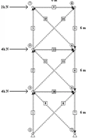
[image:7.595.295.452.74.322.2]Figure 2. Plane truss phase one design.
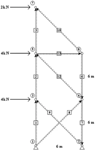
Figure 3. Plane truss final design.
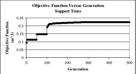
[image:7.595.294.454.358.640.2]DOI: 10.4236/mme.2017.73006 80 Modern Mechanical Engineering Figure 4. Objective Function versus Generation.
to the constraint subroutine and assigned a poor default value for both stress and displacement constraints.
5. Phase Two
The phase two optimization process is used to refine the best design from phase one by the implementation of domain specific knowledge provided by the user in the form of rules. The fundamental procedures of the genetic algorithm re-main identical to the phase one methodology with the exception of the develop-ment of sophisticated rule execution strings. Each time the genetic algorithm lo-cates a rule sequence for which both stress and displacement constraints are sa-tisfied and an improvement in the objective function is achieved, the improved design now becomes the design considered for further optimization. Four rules were developed for the phase two operation, where each rule works indepen-dently or is synchronized with other rules to improve the objective function by reducing the overall volume within the current truss structure.
Listed below are the four rules developed which can be utilized in order to improve the phase one final design.
Rule 1
Rule one manipulates the area of elements selected by the genetic algorithm based upon calculated stress. Before genetic optimization begins, the user speci-fies the maximum allowable area each element can acquire. Upon the selection of rule one, the genetic code locates the maximum element stress within the current design and a comparison is made to the maximum allowable stress con-straint. If the computed maximum element stress exceeds or falls below the maximum allowable stress constraint, then the area of the element pre-selected by the genetic algorithm is altered by a factor of 0.1 to 0.9 with a step size of 0.1. Once the area has been altered, the new area is evaluated by the maximum al-lowable area constraint, where areas which exceed the constraint are not intro-duced into the creation of a new design.
Rule 2
Similar to rule one, rule two manipulates the area of elements selected by the genetic algorithm. Area manipulation is based upon calculated nodal displace-ment rather than eledisplace-ment stress. Once the selection of rule two has been
identi-Objective Function Versus Generation Support Truss
0 0.05 0.1 0.15 0.2 0.25
0 100 200 300 400 500
Ge ne ration
O
bj
ec
ti
v
e F
unc
ti
o
n
(m
^
3
DOI: 10.4236/mme.2017.73006 81 Modern Mechanical Engineering fied, the genetic code locates the maximum nodal displacement from the current design and a comparison is made with the maximum allowable displacement constraint. If the computed displacement value exceeds or falls below the maxi-mum allowable displacement constraint, the area of an element predetermined by the genetic algorithm is altered by a factor of 0.1 to 0.9 with a step size of 0.1. Once the area of the selected element has been manipulated, a maximum allow-able area constraint determines if the altered area is a legitimate area to be con-sidered for the creation of a new design.
Rule 3
The objective of rule three is to expand or compress element length, which is accomplished by altering the nodal coordinates of pre-selected nodes. Rule three manipulates the coordinates of non-force and non-ground nodes which are se-lected by the user. A user defined coordinate manipulation constraint was de-veloped to specify how much each nodal coordinate can either be compressed or expanded. When rule three is selected nodes within the current design are ex-amined to ensure that each predefined node still exists within the current design. Nodes that are no longer contained in the best design but were pre-selected to allow nodal coordinate manipulation are simply ignored. Once a pre-selected node is found within the current design, the genetic code determines if the coor-dinates of the particular node are to be expanded or compressed. Once the ex-pansion or compression decision has been executed, the nodal coordinates are evaluated by a coordinate constraint which includes both the x and y directions to ensure that the manipulated coordinates fall within predefined guidelines.
Rule 4
DOI: 10.4236/mme.2017.73006 82 Modern Mechanical Engineering node does not connect to the same node(s) that the higher order node connects with new element(s) are created which connect the lower order node to the node(s) that connect with the higher order node.
6. Phase Three
The third and final phase of the truss optimization algorithm minimizes the overall volume of the best structure generated from phase two by reducing the area of truss members present. Area reduction is implemented by the use of a traditional global genetic algorithm search. Each element area can potentially be multiplied by a factor of 0.1 to 1 with a step size of 0.01. A phase three or global refinement search is not only necessary to further reduce the areas of the truss members present but to allow preset constraints to become active. The rules de-rived within phase two permit an increase or decrease in element area depending on specific rule criteria, however phase two aims to locate the optimal design topology which can be constructed from a “blank sheet of paper” point of view. An optimal topological design may be located to sustain loading conditions and satisfy constraints however satisfied the constraints may not be active. Hence a rigorous global search for the optimal area configuration is incorporated to en-sure that the maximum amount of material is removed while locating an active constraint solution.
7. Results
The specific input parameters utilized for each of the design exercises including population size, and number of generations of offspring to produce for both the phase one and phase two search processes are documented in Table 1. From this table, it is noted that both the population size as well as the number of genera-tions increased as the number of elements increased in the phase one search. These parameters for phase two search remained constant, regardless of the number of truss elements contained in the design space mesh. This is a direct correlation to the length of the encoding string which increases for phase one as the number of elements increases, but remains fixed for the phase two search component. The results for each truss structure considered will be reviewed in detail. The phase one search is equivalent to a traditional genetic optimization, while the phase two search procedure represents the rule based, global search process.
[image:10.595.210.542.671.723.2]The number of function evaluations required to run each example problem
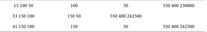
Table 1. Truss Function Evaluations.
Number of Phase One Phase One Phase Two Phase Two Phase Three Phase Three Function Truss Elements Populations Generations Populations Generations Populations Generations
Evaluations
15 100 50 100 50 550 400 230000
33 150 100 150 50 550 400 242500
DOI: 10.4236/mme.2017.73006 83 Modern Mechanical Engineering considered is determined via the equation
Function Evaluations = PopulationSize*GenerationSize (6).
8. Example One
The first example is a fifteen element plane truss formulated by Logan [8] shown in Figure 1. The point of origin was ground node one. The plane truss was op-timized with three sets of user defined genetic input parameters listed in Table 1. The initial modulus of elasticity and constant cross sectional areas for each element were preset to 210 GPa and 3E−4 m2 respectively. Maximum allowable
stress and displacement constraints were 8 MPa and 0.002 m. Nodal forces ranging from 2000 N to 4000 N were applied to nodes three, five, and seven re-spectively. The phase one optimized fifteen element plane truss is provided in Figure 2 followed by the final design encompassing the combined outcome of both phases two and three is illustrated in Figure 3.
The phase one genetic optimization process removed five elements which in-cluded the removal of node eight. Both stress and displacement constraints were not violated at the conclusion of phase one however neither concluding con-straint values are active. Since stress and displacement concon-straints are not active (i.e. g1(x), g2(x) > 0), at the conclusion of the phase one process, further
im-provement is possible. Figure 3 shows the final phase two result from which ex-ecuted rules based upon domain specific knowledge are applied. Results con-sisting of objective function illustrating reduced truss volume and constraint values versus generation for the complete optimization process are provided in Figure 4 and Figure 5. Lastly, structural characteristics composing of the design in Figure 3 are depicted in Table 2 which outlines optimized element areas and modulus of elasticity values.
Recall that constraint values result from Equations (4) and (5) which produce constraint values without units.
9. Example Two
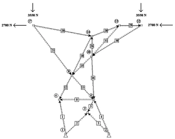
A transmission line truss developed by Logan [8] is shown in Figure 6 and is the next truss structure investigated. This thirty three element truss was subjected to two nodal forces applied to nodes twelve and seventeen. The point of origin was
Figure 5. Constraint versus Generation.
Constraint Versus Generation Support Truss
-0.1 0 0.1 0.2 0.3 0.4 0.5
0 100 200 300 400 500
Ge ne ration
C
o
ns
tr
a
DOI: 10.4236/mme.2017.73006 84 Modern Mechanical Engineering Figure 6. Transmission line truss.
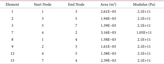
Table 2. Plane truss phase three design parameters.
Element Start Node End Node Area (m2) Modulus (Pa)
1 1 3 2.61E−03 2.1E+11
2 3 5 1.94E−03 2.1E+11
3 5 7 1.39E−03 2.1E+11
7 4 2 3.16E−03 1.05E+11
8 1 4 1.58E−03 2.1E+11
9 2 3 1.61E−03 2.1E+11
12 4 5 1.58E−03 2.1E+11
15 7 4 2.39E−03 2.1E+11
located directly under node seventeen at the ground level. The creation of this point of origin allowed all nodal coordinates to have positive x and y values. Nodal forces consisted of 2780 N and 3558 N, forces both in the negative x and y directions. Additional parameters consisted of an initial cross sectional area of 0.001935 m2 and a modulus of elasticity of 210 GPa for all elements considered.
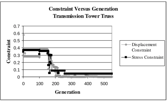
Preset stress and displacement constraints were 12 MPa and 0.00635 m. The phase one optimized transmission line truss is provided in Figure 7 followed by the final design encompassing the combined outcome of both phases two and three is illustrated in Figure 8. Results consisting of objective function illustrat-ing reduced truss volume and constraint values versus generation for the com-plete optimization process are provided in Figure 9 and Figure 10. Lastly, structural characteristics composing of the design in Figure 8 are depicted in Table 3 which outlines optimized element areas and modulus of elasticity val-ues.
10. Example Three
[image:12.595.208.539.325.455.2]DOI: 10.4236/mme.2017.73006 85 Modern Mechanical Engineering Figure 7. Transmission line truss phase one result.
Figure 8. Transmission line truss final design.
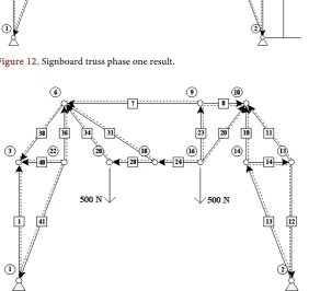
truss structure examined within this literature. This forty-one element truss was subjected to two nodal forces applied to nodes twenty and sixteen. The applied load is the total weight of the signboard divided by the two identified support nodes. Each force node supports 500 N in the negative y direction. The point of origin designated for this example was specified at ground node one. Additional structural properties included a modulus of elasticity provided by Logan [8] of 290E9 Pa and a constant cross-sectional area of each element of 3E−4 m2. Preset
[image:13.595.236.515.331.552.2]DOI: 10.4236/mme.2017.73006 86 Modern Mechanical Engineering Figure 9. Objective Function versus Generation.
Figure 10. Constraint versus Generation.
followed by the final design encompassing the combined outcome of both phas-es two and three is illustrated in Figure 13. Results consisting of objective func-tion illustrating reduced truss volume and constraint values versus generafunc-tion for the complete optimization process are provided in Figure 14 and Figure 15. Lastly, structural characteristics composing of the design in Figure 13 are de-picted in Table 4 which outlines optimized element areas and modulus of elas-ticity values.
11. Conclusion
This multi-phase genetic algorithm approach resulted in the minimization of element volume while satisfying both stress and displacement constraints. Addi-tionally, the inclusion of domain specific knowledge enabled the algorithm to generate alternative designs through the formation of new truss elements. Table 5 illustrates the total structural volume removed during each phase for each truss example investigated. Overall, through the use of domain specific knowledge, the genetic algorithm solution search is enhanced through solution convergence and intelligent design. Although the design outcome of the truss structures
pre-Objective Function Versus Generation Transmission Tower Truss
0 0.05 0.1 0.15 0.2
0 100 200 300 400 500
Generation O bj e c ti v e F unc ti o n (m ^ 3 )
Constraint Versus Generation Transmission Tower Truss
0 0.1 0.2 0.3 0.4 0.5 0.6 0.7
0 100 200 300 400 500
DOI: 10.4236/mme.2017.73006 87 Modern Mechanical Engineering sented in Examples 2 and 3 do not illustrate symmetry, the intent of this rule based methodology is to illustrate the creativity enhancement within the design
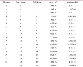
Table 3. Transmission line truss phase three design parameters.
Element Start Node End Node Area (m2) Modulus (Pa)
1 1 4 1.43E−03 2.1E+11
2 1 3 1.14E−03 1.26E+11
3 2 3 4.84E−04 2.1E+11
4 2 6 1.66E−03 8.40E+10
5 6 3 5.61E−04 2.1E+11
8 6 4 9.68E−04 2.1E+11
12 8 4 1.59E−03 2.1E+11
13 8 6 6.58E−04 2.1E+11
15 10 8 9.68E−04 2.1E+11
16 10 6 7.55E−04 2.1E+11
18 14 8 1.84E−03 6.30E+10
20 17 14 8.51E−04 4.20E+10
21 17 8 1.72E−03 2.1E+11
26 10 14 6.97E−04 2.1E+11
28 14 13 4.45E−04 6.30E+10
29 13 12 3.10E−04 1.26E+11
30 12 10 1.68E−03 2.1E+11
31 13 10 1.16E−03 8.40E+10
Table 4. Signboard truss phase three design parameters.
Element Start Node End Node Area (m2) Modulus (Pa)
1 1 3 3.09676793078184E−04 147000000000
7 9 6 4.9677318769455E−04 210000000000
8 9 10 1.67741593847275E−04 210000000000
11 13 10 1.80644800769091E−04 210000000000
12 13 2 3.29031593847275E−04 126000000000
13 2 14 4.19353984618187E−04 210000000000
14 14 13 6.45160009613633E−05 21000000000
18 14 10 2.77418804614544E−04 105000000000
20 16 10 1.29032001922727E−04 147000000000
23 16 9 8.38707969236374E−05 189000000000
24 16 18 1.09677201153636E−04 63000000000
28 18 20 7.7419198269546E−05 210000000000
31 18 6 6.45160009613633E−05 168000000000
34 20 6 1.35483595770001E−04 210000000000
36 22 6 2.12902808459997E−04 210000000000
38 6 3 1.87096394616365E−04 210000000000
40 22 3 7.09675996154547E−05 210000000000
[image:15.595.203.540.436.732.2]DOI: 10.4236/mme.2017.73006 88 Modern Mechanical Engineering Figure 11. Signboard truss.
Figure 12. Signboard truss phase one result.
[image:16.595.235.518.432.698.2]DOI: 10.4236/mme.2017.73006 89 Modern Mechanical Engineering Figure 14. Objective Function versus Generation.
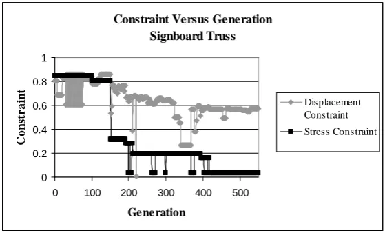
Figure 15. Constraint versus Generation.
Table 5. Volume Removed per Genetic Algorithm Phase. Volume Removed Phase
1 (m3)
Volume Removed Phase 2 (m3)
Volume Removed Phase 3 (m3)
Plane Truss 0.11278006 0.14803488 0.2237124
Transmission Line
Truss 0.021528924 0.105182161 0.1721993
Signboard Truss 0.014329714 0.047476224 0.0855189
process through the injection of domain specific knowledge.
References
[1] Smith, J., Hodgins, J., Oppenheim, I. and Witkin, A. (2002) Creating Models of Truss Structures with Optimization. ACM Transactions on Graphics (TOG), 21, 295-301. https://doi.org/10.1145/566654.566580
[2] Hamza, K., Mahmoud, H. and Saitou, K. (2003) Design Optimization of N-Shaped
Roof Trusses Using Reactive Taboo Search. Applied Soft Computing, 3, 221-235.
https://doi.org/10.1016/S1568-4946(03)00036-X
Objective Function Versus Generation Signboard Truss 0 0.01 0.02 0.03 0.04 0.05 0.06 0.07 0.08 0.09
0 100 200 300 400 500
Generation O bj e c ti v e F unc ti o n (m ^ 3 )
Constraint Versus Generation Signboard Truss 0 0.2 0.4 0.6 0.8 1
0 100 200 300 400 500
[image:17.595.207.538.497.575.2]DOI: 10.4236/mme.2017.73006 90 Modern Mechanical Engineering
[3] Sandgren, E. and Cameron, T.M. (2002) Robust Design Optimization of Structures through Consideration of Variation. Computers and Structures, 80, 1605-1613.
https://doi.org/10.1016/S0045-7949(02)00160-8
[4] Kepler, J. (2002) Structural Optimization as a Design and Styling Tool.
[5] Leger, C. (2000) Performance Characterization of an Automated System for Robot Configuration Synthesis.
[6] Goldberg, D.E. (1989) Genetic Algorithms in Search, Optimization and Machine Learning. Addison-Wesley, Boston.
[7] Davis, L. (1991) Handbook of Genetic Algorithms. Van Nostrand Reinhold, New
York.
[8] Logan, D.L. (2000) A First Course in the Finite Element Method Using AlgorTM.
2nd Edition, Brooks/Cole, Pacific Grove.
[9] Microsoft Corporation (1998) Microsoft Visual Basic Version 6.0. Microsoft Cor-poration, Albuquerque.
[10] Kawamura, H. and Ohmori, H. (2001) Computational Morphogenesis of Discrete
Structures via Genetic Algorithms. Memoirs of the School of Engineering, Nagoya University, 53, 28-55.
[11] Frame 2D (2003) Frame 2D. http://www.ainet-sp.si/AMSES/En/Frame_2D.htm
Submit or recommend next manuscript to SCIRP and we will provide best service for you:
Accepting pre-submission inquiries through Email, Facebook, LinkedIn, Twitter, etc. A wide selection of journals (inclusive of 9 subjects, more than 200 journals)
Providing 24-hour high-quality service User-friendly online submission system Fair and swift peer-review system
Efficient typesetting and proofreading procedure
Display of the result of downloads and visits, as well as the number of cited articles Maximum dissemination of your research work