PR0L15TITE PARAMETRIC OSCILLATORS by
Harvsy N. Rutt
Thesis submitted for the Degrse of Doctor of Philosophy
ABSTRACT FACULTY OF SCIENCE
ELECTRONICS
Doctor of Philosophy
PROUSTITC PARAMETRIC OSCILLATORS by Harvey Nicholas Rutt
The design and operation of a tuneable proustite parametric oscillator is described. This device reliably produced high output powers tuneable from loB to 2.5 microns. The performance of the oscillator described compares very favourably with the only previous report of parametric oscillation in proustite.
In order to construct this device b high-powered single frequency neodymium laser was required. A. two-step electro-optic Q-switching technique which produces high single longitudinal mode powers has been successfully developed.
A further requirement for construction of the oscillator was the design and fabrication of broad-band anti-reflection coatings for the proustite crystal. Details are given of a theoretical study of these coatings, and of the techniques used in their manufacture.
TABLE DP CnUTENTS
Page CHAPTER ONE. Introductory Remarks
]. .1 Tuneable Coherent Medium Infra-Red Sources 1 1.2 Parametric Oscillators Bsjsed on Proustite 3 CHAPTER TWO. Design of the Proustite Parametric Oscillator
2.1 Choice of Pump Source 5
2.2 Phase-Hatching Considerations 6
2.3 Intensity Thresholds of Optical Parametric
Oscillators 8
2.4 Thresholds in Plane-Curved Resonators 12 2.5 Numerical Estimates of the Steady-State OPO
Threshold 15
2.6 The Oscillator Resonator 18
2 . 7 Effect of Mode Mis-match 20
2.6 Dynamic Thresholds 21
2.9 Pump Spectral Requirements and OPO Tuning
Characteristics 25
2.10 Proustite Damage Threshold and Final Oscillator
Design 28
CHAPTER THREE. A Tvjo-Step Q-Switching Technique for Producing High Single Longitudinal Mode Power
3 o1 Introduction 31
3.2 Design Considerations 32
3.2.1 General 32
3.2.2 Resonant Reflectors 33
3.2*3 Effects of Temperature 35
3.2.4 Control of the Build-Op Time 37
3.2.5 Additional Factors 39
3.3 Experimental Method 40
3.4 Experimental Results 44
Pane CHAPTER FOUR. Ultra Broad-Band Multi-L^yur Anti-Reflection
Coatings for the Infra-Red
4.1 Introduction 4 7
4.2 Basic Design 4 7
4.3 The 'Ideal' Coating 4B
4.4 Effect of Limitations on ths Lowest Available
Costing Index 51
4.5 Effect of Restrictions on ths Refractive Index
of Intermediate Layers 53
4.6 Effect of Thickness Errors 55
4 . 7 Experimental 57
4,7.1 General 57
4 • 7 . 2 Three-Layer Coating for the DPO Experiment 58
4.8 Conclusions 59
CHAPTER FIVE. The Parametric Oscillator Experiment
5.1 Experimental Technique 6l
5.2 Experimental Results 62
5.3 Conclusions 64
REFERENCES 65
CHAPTER ONE INTRDDUCTDRY REMARKS
1.1 Tuneable Coherent Medium Infra-Red Sources
Tuneable consrent mBdiurn intrB—red sources hsvs numerous possible applications, especially in spectroscopy and allied fields. Their very high brightness' (watts/cm /steradian) enables their output to be focussed into a very small spot, or to be propagated over very long paths without excessive beam spread. Further, they are capable of frequency resolutions considerably better than those achievable by conventional techniques, and the availability of very high powers in a narrow bandwidth permits experiments which would not otherwise be possible, such as the pumping of selected
vibrational levels.
Substantial success in producing tuneable coherent sources for the visible and near infra—red has been achieved by using optical parametric oscillators. Many of these oscillators have been based on lithium niobate, and a paper by Wallace (1970) gives an excellent picture of the 'state of the art' with this material. In this paper a device tuneable over the range 0.55 pm to 3.65 |im is described. The pump source used is the second harmonic of various lines of a neodymium YAG laser, and high
conversion Efficiencies with prolonged, stable, narrow—band operation was achieved. Lithium iodate has also been used as the active material in a parametric oscillator which tuned from 2.5 p. to 4 um when pumped by a rubv laser. This appears to be the longest wavelength so far generated by an optical parametric oscillator (OPO).
prnustite (Ag AsS^), pyrargyrite (Ag^SbS^), cadmium selenidE (CdSe), cinnabar (a HgS), and the ternary compounds such as silver gallium sulphide (AgGaS^) and zinc germanium phosphide (ZnGeP ). As fsr as is known, only the first three materials are available in device quality crystals, and proustits is the only one to have been used successfully in an OPO to date.
At least three altsrnative approaches exist for generating tuneable coherent medium infra-red radiation. An approach which is closely related to parametric oscillators is difference mixing of the outputs of a ruby laser and a dye laser in a non-linear crystal. Dewey and Mocker
(1971) have generated 6 kW of radiation at 3-4 lim by this means in LiNbO^. The technique can be extended further into the infra-red by uSj.ng one o i the crystals mentioned above, and could well have significant advantages over a parametric oscillator for certain applications.
The second technique is the use of lead tin telluride diode lasers. By varying the proportion of lead to tin, diodes can be made which emit anywhere from 6.5 to 32 and Kelley, 1971) However, an
individual diode can only conveniently be tuned over a range of about 40 wave numbers, so that a very large number of diodes would be required for
\
broad-band tuneability. Where narrow-band tunsability about a fixed wavelength is required, this approach may well be the best, although the power outputs from diode lasers are very much lower than those from ths other devices described.
The third technique uses stimulated inelastic scattering from the spin states of conduction electrons in indium antimonide, and is usually known as the spin-flip Raman laser. Spin-flip devices have been tuned from 5.2 to 5.6 p.m, 9 to 10 |im, and 10.9 to 14.6 u^/Wherratz, 1971;
1 kW hrjve been achieved, and spin-flip dsvicca have the advantage of very narrow linewidths and smooth tunsability. However, ti^sse devices suffer from the substantial disadvantage of requiring large superconducting magnets and a supply of liquid helium.
1 • 2 Parametric Oscillators Based on F'roustite
Prousti.te is an attractive materiel far medium infra-red parametric oscillators J since it is available in large, high quality crystals, possesses substantial non-linearity, transmits from 0.65 to 13 |j.m, end has sufficient birefringence to phase-match virtually any non-linesr
. . , , . (Bardsley et al., 1569) ,,, , process with.in its transmission range. ' When used in a parametric oscillator pumped at 1,06 ^m it should be capable of generating an output tuneable at least from i«2 to 9.5 |im.
However, proustite has one major disadvantage, that is its suscepti-bility to surface damage by laser beams. The performance of the only
. , . , , , . 1 - L .(Arnmsnn and Yarborough, other proustite oscillator which has been published ' 1 970)
was severely limited by this. Ammann and Yarborcugh used a
f\!d :YAE laser pump power of 4D0 watts, at 2000 pps, with a power density
2
of 0o9 MW/cm" incident on the crystal. They reported that oscillation only occurred on a small percentage of pump pulses and had a long build-up time; they did not give details of the output power, conversion efficiency, or tuning range. They also state that oscillation could only be obtained for a few minutes in each region of the crystal before surface damage occurred.
The work described in this thesis began approximately two-and-a-half years ago. It was immediately apparent that surface damage would be the major difficulty in constructing a reliable proustite parametric oscillator, since preliminary measurements of the damage threshold were available
initial experiments confirmed the low values for surface damage already r e p o r t e d .
Efforts were therefore concentrated on designing the proustite o s c i l l a t o r to have the lowest feasible intensity thresholdo For this reason, consideration was given only to ths doubly resonant parametric oscillator, since although the singly resonant oscillator has many
,, . (Smith, 1971) , , , . , ,, , . , ,,
attractive properrzes * it has a much higher threshold than the doubly-resonant oscillator* Fortuitously, the pump source chosen was a medium repetition rate system (up to 10 pps), since proustite's damage threshold is now known to depend strongly on the pulse repetition
, , . , jr L. - u , . , . , (Henna et al., 1971) rate, being lower for high repetition rates»
Successful operation of the proustite OPO required considerable developments in two technological areas. Firstly, a high powered
Q-switched single frequency laser was essential, and secondly a variety of m u l t i - l a y e r dielectric coatings, and in particular broad-band anti-reflection costings for the proustite crystal, were needed.
5.
CHAPTER TWO
DESIGN OF THE PROUSTITE PARAMETRIC OSCILLATOR
The long-term aim of expRriments on O.P.O. in proustite is to obtain oscillation tuneable over a wide brandwidtho Such wide-bsnd tuneability requires complex oscillator resonators, and the initial experiment v.'as therefore designed only for narrow-band, near degenerate operation. This simple device can be used to obtain information for the design of a broad-band oscillators
2 . 1 Choice of Pump Source
The neodymium ion in a crystalline host is the obvious choice for pumping the proustite oscillator for many reasons.
Firstly, the major neodymium line at about 1.06 (xm is well away from proustite's short wave absorption edge at D.62 p.m, thus reducing the likelihood o f laser damage to the proustite crystal.* Secondly, using this pump source degenerate oscillation occurs at 2.12 |im, allowing the idler output to cover the whole of ths possible range of oscillation which is o f major spectroscopic interest (1.2-9.5 lim). Thirdly, Nd^"" in calcium tungstate and YAE are readily available, well developed laser materials, capable of operation at high repetition rates with high output powers. Other host lattices (for example, fluoro-apatite, yttrium ortho aluminate and lanthanum oxysulphide) are being developed and may also be suitable in ths future. Lastly, the use of this wavelength satisfies the practical phase matching requirements detailed in section 2.2 below.
Two other pump sources were considered; ruby at Do6943 [im and holmium-YAG at 2.098 [im. However, at the ruby wavelength proustite's
6,
(HLRSS)
laser damage threshold is considerably lower " , and ruby lasers cannot readily bs run at high repetition rates with high output powers. Holmium-YAG lasers have to be liquid nitrogen cooled, which is • undesirable in a practical system, and proustite's damage threshold is not appreciably higher at 2o09S (im than at 1.06 |im» Neither system has any apparent advantage over the neodymium pump source.
2.2 Phase-Matching Considerations
For a loD6 pump there are two possible phase-matching schemes.
-r T I e . o D
Type I k = k + k. —p — s — 1
_ ^ T , e , o , e
Type II k = k -f k. — s — X
When choosing between these, several factors must be considered. In designing a bread-band oscillator, this use of Type I phase-matching would probably be desirable, since this leads to the signal and idler being orthogonally polarised to the pump. This is useful, since it allows various schemes for coupling the pump into the broad-band resonator which rely on this polarisation difference to be used.
Further, the type of phase-matching determines the effective
d coefficient. For proustite, point group 3m, the effective coefficients , (Midwinter and Warner, 1965)
are given by '
Type I F^O.Gfjd) = d^^sinQ - d ^ ^ c o s O s i n S j ... (2.1)
Type 11 F^(B,(|j,d) = d^g c o s ^ B c o s S ^ ... (2.2)
B is the phase-matching angle (the angle between the direction of propagation and the optic axis, x ) and ^ is the angle between the X X plane and the plane containing the direction of propagation and
r
-the X axis. F is a maximum w h e n © = 0. F is a maximum whan
j 1 -t- 2
1 hB nycGssary condi ui DPS for this Ccn bs found by rc^fersncs to the Lsu X-ray photographs of the c r y s t a l . J o n e s , Davis and Hobaen, 1967)
The same authors give the d coefficients relative to LiWbO^ as
^31 = Z.G
p p
'^22^~^31
~ ^ ^ i O . l
using = 1.5 x 10 ® e.s.u. (from Boyd and Kleinman (BK), 1968. This voliiB uses the best available estimate for the absolute coefficient of ADF , and various relative measurements between KDP, ADP and LiNbO .) Therefore
P - 8
= 3o9 X 10 e.s^Uc
dg_ - 6.25 X 10 ® e.SoUo
Using chs refractive inasx data of Hobdsn, 1970, to obtain the phase—matching angle and double refraction a n g l e , g i v e s , at degenerate, the values shown in the table below.
1.065 p,m Pump 0 Match d 6 * 2 * U #
LrF y^rads
Type I 29°2G' 7.4 X 10~® 0.078 Type II 43°49' 3 X ia~® 0.091
a
The effective coefficient for Type I matching is thus 2,5 times the coefficient for Type II matching, reducing the oscillator threshold by a factor of 6. A curve giving the phase-matching angle (Type I) as
function of the signal and idler wavelengths is given in Fig. 2.1. The range of angles required to tune the oscillator across its whole range is 13 internal. This is a fairly convenient angular range,
A much smaller range would make accurate tuning difficult, whereas a much larger range would be physically inconvenient and would sdd to the
Typs II phase-matching would resLilt in n much larger angular range.
2.3 Intensity Thre'-shol.ds of Jin ticsl Paramntric Oscillators
G.D. Boyd and Kj.einman have published a comprehsnsive analysis of the 'Parametric Interection of Focused Gaussian Light Beams', 1968
(hereinafter referred to as BK). In this paper they derived the
'optimum' focusing and 'optimum' crystal length which minimised the pump power, P, required to achieve optical parametric oscillation (DFD) in a given systems This optimisation has proved very valuable in obtaining DPD in the visible and near infra-red. (The first CW oscillator
ol., 1 ^ 6 6 ) on Ba^NaNb^D^^ provides an excellent example of the application of BK power optimisation.)
Unfortunately, the price to bs paid for decreasing the power threshold is an increase in intensity (power density) at the crystal. In many cases of practical interest for infra-red parametric oscillators (examples;
proustit.B pumped by loD6 |im, tellurium pumped by 10,6 (im or 5.3 jim) the threshold powers are very much lower then the available laser power, but the intensities approach, or even exceed the damage limit of the non-linear material. Derived here, from BK' s ttieory, is the pump intensity threshold, I, for OPO and from this result it is clear that BK's
'optimum' focusing and crystal length should not be used with damage-prons materials. Compromise values of length and focusing which result in much reduced intensity threshold with only a modest increase in power threshold are given. These results are only applicable to critically-matched
oscillators (B > lo6B), but this covers currently available infra-red non-linear materials.
In what follows the symbols* and equation numbering sre consistent with BK. Restated here are the major parameters:
the cloub 1G-rEfrac;tinn dnramc-1er:
,
.1.
Z f ( t k )'/2 (BK 3.35)
/
where 't is the physical length of the non-linear crystal, the Jouble-refraction walk-ofT angle, and k c the signal/idler dsgenernte wave-constant;
the; focusinq oarameter:
= C / h (BK 1.3),
where b is the pump (sarns for signal and idler) confocal parameter inside the crystal;
tlig reciprocal pump threshold function j
h^/B,^) 3.37).
This function includes the effects of double-refraction and
diffraction. The subscript m represents optimisation (maximisation) with respect to phase rriismatch. A subscript mm indicates a second optimisation with respect t o ^ , yielding;
^ J B ) (BK 3.36),
and consequently the minimum power threshold, P » opt
Using the approximate forms of h^(B,J) for weak focusing
("^ < 0.4 (BK 3.51)), and h^^^(B) for strong double-refraction (B > 1,69 (BK 3.48)), it is readily shown that:
" ... (2.3)
^opt ) erf (E
Pump intensity is defined as that at the centre of Gaussian beam;
I =
10.
and b = k W gives
I 4B^
^opt ^ erf (3 ^
( < 0.4). ... (2.4)
I is now ths minimum intensitv threshold.
Re-normalisation of the focusing parameter allows the removal of B as an explicit parameter and prssentation of the functions (2.3) and
(2.4) as a general pair of curves;
A = ^
P
' opt erf ('\4cA/2) ^
(2.5)
I
( 2 . 6 )
I r — 9 *
opt erf ('VnA/2)
Expressions (2.5) and (2.6) are plotted in Fig. 2.2 against the normalised p a r a m e t e r A. The curves cross at A = 1, that is where, ^ the two ratios then having the value l o 6 0 3 . As expected,
3s 0. P/P^pX is also asymptotic to unity, for large ^ . The ,latter, of course, just represents the approach to BK's optimum focusing condition. Ths failure of this curve to rise again for very large (see BK Fig. 12) is simply due to the nature of the approximation used for h^ (B,"^ ) o
11
psranister required to obtain 3K 'optimum' focusing is generally vary short end difficult to achieve nn practice; always requires a much larger value of
A further optimisobls paremeter is the length of the non-linear crystal. Here again the results from considering intensity threshold dzfier from thoss i or pcv-'sr threshold o The ons—wey losses of the oscillator are defined (BK 3.74) as:
G = e + a (a « 1)
o o o
and also x = ^ By working at ^ ^ the length dependence of the intensity and power thresholds are readily obtained from equations (2.3) and (2.4) above and (BK 3.34). The results are;
, 2 « (1 + x)'
= (i + X
(2.7)
These functions are shown in Fig. 2.3, where it is seen that neither curve possesses a minimum. This is in contrast to BK 'optimisation', wh^re P(x) has a minimum, always at x ^ 1 (BK Figo 13). Tha intensity threshold approaches its smallest value for i- » C , the loss from o:
o 'o
then dominating. In contrast the power threshold optimises for C « C
o curves with the z loss becoming the most important. For ^ f the two
cross at L = with thresholds each four times larger than minimum. There is thus no clear compromise value for crystal length as there was for the focusing parameter; the actual length chosen will depend
strongly on the laser pump power available, non-linear crystal parameters, etc. Once again the BK 'optimum' length is inconveniently short for many infra-red materials (often less than 1 mm), and it is therefore better to work with lengths substantially larger then u •
12.
In interpreting these results several points need to be considered. Firstly, the intensity thresholds derived above refer tc the focus of the Gaussian beam. Where surface damage is the limiting factor, a slight • correction may be required to find the surface intensity. Since, however, ^ << 1 for most materials, this correction is very small»
Secondly, the limits of B > 1,66, < f.1o4 must be observed for the results to be valid. Consideration of all cases of practical interest in proustite and tellurium shows that- the first condition is easily met and that ^ is then << 0.4.
The third, and perhaps most important consideration, concerns the confocal parameters of the parametrically interacting beams. Assumed in BK, and therefore also in this work, is the condition:
b = b = bj (= b) (BK 3.12),
where b^, b^ and b^ are the confocal parameters for the signal, idler and pump beams respectively. This limits, in general, application of these results to doubly-resonant oscillation (DRO).
Finally, in deriving equation (2.7), it has been assumed that
<< 1 (as in BK). For some materials, (e.g. tellurium) this may not be valid. The effect will be to modify the exact forms of (2.7), but not the general condlusion that longer crystals should be used to minimise the intensity threshold.
2.4 Thresholds in Plane-curved Resonators
13,
Arrmionn and Montgomery, 1970, have published an extension of BK's analysis to plane-curved resonators. Starting from their paper, it will bs shown here that, for strong double refrnction and weak focusing, the results of AM very closely approximate those of BK and hence that the 'intensity threshold' analysis of the preceding section 2.3 is also valid for this second type of resonator.
For convenience, AM' s Fins. 1, 2 and 3 are reproduced in Fig. 2.4. , The pump, signal and idler beam waists ere all assumed to be located at the crystal surface adjacent to the plane mirror; the pump beam axis crosses the signal and idler a x e s at a distance K'd- from this surface, where 'C is the physical length of the crystal. K is always 0.5 in SK.
In order to prove that the analysis of section 2.3 is also valid for the plane-curved geometry, it must be shown that the functions in AM which are analogous to h (B, ) and h (B) ere in fact essentially
^ m ' mm .. j
equal to thsm for the values of B, which are of interest. The relevant functions are derived from
_ __ 2
H(Crp,^) (BK 3.32) end
2 . -
2
hOZ,K,p,^) = H(orK,p,^) (AM (16))
where the phase mismatch parameter O'= bAk/2 and p = B/^T. Hence it is required that H (cr, p,^) H{C, for the cases of interest. Again the subscript m represents optimisation with respect to 0", end subscript mm optimisation with respect to G" and ^ .
Now;
-+ 2 2
14
r- 2 ""1
Making the spproximat.ion (1 + i'f) ^ - o^^j] + - ... | • • •
L -J
+ 9
yields = (2:%)"'^ j exp(i(Cr_ D t
-" 5
Evidently Q~' = 1 so that
^>erf(p^!)/2%zp g < < 1 (BK 3.50)
The limit on g is in fact ^ < 0.4 (BK 3.51)
2
and the neglected term in deriving BK 3.50 was of the order o f % ,2 having a maximum value of ^ /2.
Continuing;
-2 ^ S.
H\o%K,p,^) = (2%)"1 j e x p ( - | i O r ? + ^ p ^ ( ? - 2K^;)J^ 0
If we let K = Do 5, the value used in BK
H(0-,0.5, e,?) = (2li) ^ ' j e x n
2 _ J " ^ ... {2o1D) D
Using the same approximation give 2 %
H(oio.5,p,^)-»(2%):^ ^ e x p [ i ( i -(r)i;-0
A g a i n c r = 1 s o
m
2 ^
j e x p [ - «
Letting ^ ^
f=
- !
15,
2
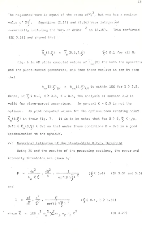
The neglected term is again of the order , but now has a maximum value of 2 ^ . Equations (2.14) and (2.16) were integrated
2
numerically including the term of order in (2.15). This confirmed (BK 3.51) and showed that
? < D.l for all Be
Fig. 6 in AM plots comouted VBIUES of h (B) for both the symmetric
. mm
and the plane-curved geornetries, and from these results it can be seen that
h (B;lr) = h (3,1;) to within 10?'j for B > 3.5. mm ' i) BK mm ' ) AM
Hence, if ^ < 0.1, B ) 3.5, K = 0.5, the analysis of section 2.3 is valid for plane-curved resonators* In general K = 0«5 is not the optimum. AM plot computed values for the optimum beam crossing point K^(B,'^) in their Fig. 7- 11 is to be noted that for B > 2, ^ < 1/B-. 0.45 < K^(B,'^) < 0o5 so that under these conditions K = 0.5 is a good approximation to the optimum.
2 c. 5 Numerical Estimates of the Steady-State O.F.O. Threshold
Using BK and the results of the preceding sections, the power and intensity thresholds are given by
2 2
4E 4B 1
and
2 ( f < 0.4) ) (BK 3.34 and 3.51)
ttK
{}
erf (B 'v^ ) ^( ^ < 0.4, B > 1.68)
[image:19.558.54.514.25.776.2]1 6 .
For a Type I phase-matched degenerate oscillator pumped by 1.D65 [.un the parameters
are;-O C ~ 1^.8 X 10 B.s.u. (effective non-linear coefficient)
= 2.75 (n^ - idler refractive index - signal refractive index n
3 pump refractive index)
0.)^ - 8.84 X 10 r a d/ s e c . (signal and idler angular frequency)
~ 8'11 X 10 cm (signal and idler wave constant)
This yields K = 3«8 x 10 e.s.UO
The double refraction parameter H = y ( ^ k ^ ) V 2 (BK 3 . 3 5 ) . For degenerate oscillation the double refraction angle =
0.078
red so that-f '2
B - 11 1/ where U is the crystal length in cm. The exact losses seen by tne oscillator are very difficult to estimate. Conventional spectro-photometers usually have a large acceptance angle, and therefore do not detect small angle scatter. Also, commercial instruments tend to be very difficult to use accurately when measuring reflectivities and transmissions close to unity or zero. This is especially true of small, thick samples. Further, the oscillator loss is affected by optical inhomogeneities which mc;y introduce additional, difTraction losses. Since no value of was
o
available, a 1 cm cube crystal was purchased for initial experiments. Thi: size was chosen since larger dimensions would have increased the difficulty of obtaining high optical quality, and it was estimated that would be
o
less than 1 cm. As indicated in section 2.3, this reduces the intensity threshold.
J,
I <•
coating are given in Chapter 4 <. The loss wns shown to be either
absorption or large angle scatter by varying ths solid angle accepted by tho dBtector from 0.5 x 2.0 " sr to lo6 x ID ' sr» This; variation
prouuced no change in thie measured loss. Proustite crystals show strono wide and smell nngle scatter at 633 nm, and fins inclusions are visible, so that wide angle scatter is the most likely loss mechanism. If this is so, the loss at 2.13 p.m should be considerably lower than that at 1«152 |im,
Ths oscillator mirrors had a reflectivity of 9 8 - 9 8 . a t 2.13 um (see section 2«5). Rough estimates of the 2.13 |j,m single pass losses are thus
G ~ 0.04 o —
a
~ o —0.1
3
Giving ~ 0.4 cm and e ^ 0.14 for this 1 cm crystal. From these values the chosen crystal length of 1 cm is reasonable. Using this value for the loss
10
2
erf( •\'iiA/2)
watts. (2.11)
I 2 . 6 X 10 A
e r f (Vt iA / Z )
For a 1 cm crystal length
2 W/cm^.
(2.12)
= 11.1
= %/4B = 0.0064.1 8 ,
!
f = 0.0064 0.00260.40
0.31 mm 0.4 9 mm
b^yy 57 cm 14 2 cm
640W 1.2 kW
I 0.42 MW/cm^ 0.32 MW/pm
It must be stressed th-::t since the threshold depends on the square of the losses, and the losses are not accurately known, the values of P and I must be treated as 'estimates'.
2.6 The Oscillator Resonator
Since the crystal losses are estimated to be of the order of 10%, there is little advantage in using very high reflectivity mirrorso For this reason a reflectivity of 98-98.5^ was initially chosen. Mirrors o f this reflectivity can be readily made with low loss, good reflectivity bandwidth, and high pump transmission. Since the pump pulse is short
(26 ns full width at half height) it is desirable to keep the oscillator resonator as short as possible to minimise the oscillator build-up time
(see section 2.8). As a compromise between this requirement, physical limitations, and cavity mode size requirements (see below) the mirrors were placed 6 mm from the crystal faces. The overall effective cavity length is therefore 16 mm. (Note that the crystal length is reduced by a factor of its refractive index for the purpose of Gaussian beam
19.
cavity 16 mm long would require ;j 5 metre radius curved nirror. The stability parameter for such a cavity is
g = 1 - ^ = 0.997
when L is the cavity length and R the mirror radiuso^"'' 1965 )
estimate cf the maximum effective lensing in the crystal was made from the Twymann-Green interferonrarn . (supp.lind by R.R.E., Malvern). This was found to be / i d metres. Use oi a 5 metre mirror would not therefore ensure stability. An attempt to measure the focal length of the coated crystal with a 633 nm laser was not successful, the large amount of scatter at this wavelength making accurate measurement of spot size impossible«
On this basis a mirror curvature of 2m was chosen. • This was considered short enough to ensure stability. An exact calculation of the cavity confocal parameter cannot be made without a knowledge of the effective focal length and nature of the inhcmogeneity in the proustite. If the effect of the inhomogeneity is negligible, the confocal parameter will be 35 cmo
In order to estimate the diffraction loss of the cavity, it is required to know both the stability parameter of the cavity and its Fresnel number. Diffraction loss calculations have been published only for a restricted range of cavity types, usually with the aperture
sumed to be at one mirror. The physical limit of the cavity aperture is the 1 cm^ face of the proustite crystalo However, once the radiation leaves the pump beam, it ceases to be amplified even though it has not been lost from the cavity and may return to the region of the pump. To obtain sn order of magnitude for the losses
a ~ G.5 mm (aperture radius) L = 16 mm
2 0 ,
A, = 2.13 |irn
giving N ^ 7.5.
The diffraction loss, for the pessimistic ;?.Gsumption of g = 1 (jiist s t a b l e ) can be estimated from T. Li (1965 ), as l.S^L
If the'effective focal length of the proustite is long enough to be ignored, the stability parameter for the cavity will be 0.992. The diffraction loss decreases vary rapidly with decreasing stability
parameter, being « 0 . 1 % for g = 0.95. Loss figures for 0.95 < g < 1 have not been published..
2.7 Effect of Mode Mis-match
As has been emphasised above, the enelyses used by BK and AM assume that the signal, idler and pump confocal parameters are equal. It is not possible to derive from their results the effect of mode mis-match. Asby (1970) has developed the theory of parametric amplification from a coupled-mode approach, for the case of zero double refraction (B = 0).
However, in the near field approximation
0.4, < 1/6B^ (BK 3.52)
the threshold derived by BK becomes independent of B. Thus Asby's
results are likely to be applicable to oscillators having double refraction provided that the above near-field condition is satisfied. Letting
b = pump confocal parameter
. = signal end idler confocal parameter V = b ./b mode mis-match parameter.
s, i ' '
Asby's eoustion 3.7 shows that, to a good approximati on
lyH « 1 + 2V + V ^ . ... (2.13)
> 1 .
is appreciably reduced by using V < 1. In particular
V = 1, •- 4 (Mode-matched)
V = D»25, = lo56 (Value used in experiment described in Chapter-5). The physical basis of ttiis result is that for V <C l/'/2 the signal and idler spot sizes are smaller than the pump spot, so that the entire signal and idler modes see a larger pump intensity.
As usual, great care must be exercised in using the result to ensure that the approximations arc satisfied. For our experimental situation, t^lB requirement is
,2
1/6B', i.e. 0.0U14
whereas ^ = 0.0026 J pump
e
. = 0.01.
The numerical results of equation (2.13) can thus only be taken as a very general guide, since the approximations are not satisfied for either beam. In addition, no exact proof has been given that Asby's results are
independent o f B in the near field approximation.
Calculations of the effect of mode mis-matching including double refraction would be valuable, and these calculations are now in progress
(H. Blok, 1971). It is evident that whilst the use of V < 1 produces a slightly lower threshold, it is likely to result in reduced conversion efficiencies and in the excitation of high order transverse modes in the oscillator if the oscillator is considerably above threshold.
2.8 Dynamic Thresholds
The theory of parametric oscillators so far discussed refers
o s c i l l s t o r cuT.put r e a c h e s an o b s e r v a b l e J.evel within the duration of the pump pulseo
No exact theory for the dynamic threshold o f HPO has been p u b l i s h e d . It is however possible to obtain a rough estimate of the effective
'dynamic t h r e s h o l d ' for our specific e x p e r i m e n t a l c o n d i t i o n s . A not d i s s i m i l a r analysis has been used by Kreuzer {1968)«
The laser pump p u l s e is approximately a Gaussian function of time, having a full width at half height of 26 ns. This is approximated by a r e c t a n g u l a r pulse having the some peak intensity and 26 ns w i d e . The
'optical' length of the oscillator cavity i s f ~ 40 mm, (allowing for the crystal r e f r a c t i v e i n d e x ) . There is thus time for M ~ 100 double passes o f the o s c i l l a t o r cavity within the duration o f the pump pulse»
Let L be the (equal) signal and idler loss, r be the transmission of the output mirror, Py bs the threshold pump power,
m i n i m u m detectable output power,
n = P^/Py the f a c t o r by which the pump exceeds threshold.
Pp. be the p a r a m e t r i c fluorescence into the DPO cavity mode, and the p a r a m e t r i c f l u o r e s c e n c e varies linearly with pump power so that
where Q includes the n o n - l i n e a r coefficient, g e o m e t r i c a l factors, etc. On propagating t h r o u g h the crystal in tlie same direction as the pump beam, the signal power is increased by a factor
w h e r e is the parametric gain c o e f f i c i e n t at t h r e s h o l d , varies ao the square root of the pump p o w e r (see, for example, G i o r d m a i n e and Miller, 1 9 6 4 ) . The signal and idler gain c o e f f i c i e n t s are equals At threshold
23,
Ignoring th/j stored energy in the cavity (which is low s:'"ice ths losses are high), the instantaneous power output after M double pr.ssEs is
T n Q exp(M&Y(n^ - 1)).
If this is s2 k equal to the smsllent detectable output power, the minimum factor above threshold (n) whiich will give a detectoble signal within the duration of the pump pulse is obta:ned
_JL
Assuming n ^>''|gi
Ln (n )
ves
3 >
wi 1
>
wi 1
J Q PT
ramsters are
p
MIN 1 D ~ \ ' T - 2 X lU
'T - 1.2 kW
L 0.14
M 100
0.33.
+ 1
It remains to evaluate Q. Several papers have bacn published which derive the approximate parametric fluorescence power radiated into a given bandwidth and solid angle«
Giallorenzi and Tang (1968) have published one such estimate. Their equation 3.5 can be rewritten in terms of our parameters as
32 d A w AO
ef f o o
c^ to n^((o ) ^"e A8 ^
R P ^
-P O O
88
P
2 4
NOVJ
A 8 is the pump divergence outside the crystal, and AQ' is the solid anglR accepted by the resonator.
9 1
n (0) e
2 N .
COS 0 s]_n 9 ,. ^ _
p 2 ~ dirTerentiatxon yieldj
n ' n
o e
6n (Q) e T O '
2R,
C O S B Sin B
-3/2
sinS cosB.
Substituting appropriate values give:
3n (8)1 e 8 8
= 0 . 1 8 6 .
?>. = l o 0 6 u.in
P
8
= 30° Mis the oscillator cavity axial mode spacing divided by its finesse.
A w
t
c (J. - L)'giving Aco 1»12 X ID reds/sec.
From Kogelnik and Li (1966), AO = &/%W where V/ is the e -1
P P P
electric field radius. Therefore A9 ~ 2 m red and Aq' ~ 0.5 x J0~^ sr. P
assuming matched confocal parameters. For a 10 mm crystal 0.4 % 10 - 1 6 . .
Substituting this value into the equation for or Q = 0.4 X 10
n gives
n ~ 4.
Hence the effective threshold for oscillation to be observed is a factor o f four higher than the c«w. threshold.
25.
2o9 Pump SDRctral Reauiremsnts and OPO Tuning C horacteristics
In a doubly resonant parametric oscillator four requirements link the pump, signal and
idlsr:-w + w -- w Energy conservation,
s a p
k -f k = k Phase-matching.
S I p
n,\ zz 2t ) , Signal resonance.
g v g m and n m ; a n n n
are integers.
m\. = 2^. ) resonance.
Where ^ ^ . are the optical length of the cavity at the appropriate w a v e l e n g t h . It should be noted that the analysis which follows is
a uniform plane wave approacho Ths results for a weakly focussed Gaussian beam will be essentially the same.
In order that the first condition is satisfied it is evidently desirable that the pump frequency have a bandwidth less than the sum of the signal and idler mode widths. If the pump bandwidth is wider than this only that portion of the pump power which falls within the width oI the combined modes will be effective in pumping the parametric oscilJ.ator.
In order to estimate the usable width of the signal and idler
resonances, the shift from the peak of the resonance should not appreciably increase the effective cavity losses (HD.IS). An effective finesse,
is therefore defined as being the ratio of the mode spacing to the width of ths resonance peak at 95%, and is numerically
R O . 9 5 _
( 0 . 0 5 ) 2
where F is the finesse of the cavity as normally defined. For a single pass loss of - 0.15, F ~ 20 and F^°^^ - 90. With a cavity optical length
- 1
the laser must oscillate in a single mode only.
As has been noted by rnnny authors (for example, Giorarasine and Miller, 1965; R.G. Smith, 1971), the tuning characteristics of the doubly
resonant OPO are complex. The oscillation frequency is controlled largely by the requirement for double re:ionancB of the signal and idler wavelengths, rather than by the requirement for maximum parametric gain.
The dependence of the parametric gain upon Ak is given by
S I N L - 2 - J
CI
2
where (, is the length of the non-linear crystal. The gain first goes to zero at A k ^ = 2n. The frequency offset from Ak = D required to give Ak'£ = 2n is given by
A W
2ti
c
6k, ^ I O W
IW. 1
A K ^
9 W 0)
where second derivatives and abo\/e have been ignored.
2V^ (cm ^) = 2Au^/27iC is plotted against in Fig. 2.6, for a 1.065 (im, pump, using the refractive index data given by Hobden, 1970.
The frequencies at which double resonance occurs are separated by the so-called'cluster spacing', Aw^. The value of A w ^ is readily shown to be Aw^/2. Giordm.aine and Miller (1965 ) state that the worst case phase
mis-match is thus produced by a shift of Aw^/4 from the point where Ak = 0, resulting in Ak = n/2 and a corresponding maximum increase in the threshold pump power by a factor of lo24.
21.
can be seen from Fig. 2.6 that the number i.if modes within the cluster is equal to P for ^ 2.27 um« For idler wavelengths 'longer than this ths nearefit frequency nt which duubls resonance occurs may be more than
away from Ak = 0, and hence, cause a greatly increased threshold. A double resonance must then be obtained within the phase-matching bandwidth by varying the cavity length.
From the above, discussion it is therefore to be expected that, very close to degenerate, oscillation will be obtained independent of fluc-tuations in ths oscillator cavity length, and pump absolute frequency, but that the frequency output will be unstable, having a bandwidth
~ Aco^o Further from degenerate however, (for > 2.3 ;im) fluctuations in these parameters may actually cause a very high threshold, and prevent oscillation. The expected bandwidth is then much narrower. For a fixed ^s' double resonance occurs for cavity optical lengths'^
such that
t
, ! . A J .
where q is integral,
I |
For example, if = 1.065 n
A.J = 2.2 [im L = q.l7 |.im A.j=2.5 ^im L = q.3.6 [imo
The oscillator resonator was therefore constructed to be very rigid to avoid variations in cavity length due to vibration, and the length was mads adjustable by a micrometer direct reading to 2 pm. The addition of a piezo-electric drive to provide finer control would be
/ O ,
2.10 ProustjtR D e m ^ q e T h r w s h o l d and F i n a l P s c i l l a t o r Design
The l a s e r system d e s c r i b e d in C h a p t e r 3 was used f o r ^ d a m u g e m e a s u r e -ments, e x c e p t t h a t the driLihle Q-zwitch t e c h n i q u e was n o t Eii;ployed. For
3-L
some m e a s u r e m e n t s a 5 cm x 3.2 mm Nd :YAG l a s e r rod r e p l a c e d the 3
-i-Nd :CaWO^. W i t h this red there vjas c o n s i d e r a b l e random s e l f m o d e -l o c k i n g , which w a s very v a r i a b -l e from stiot to shot.. However the damage t h r e s h o l d was very c o n s i s t e n t , so that the damage p r o c e s s a p p e a r s to
average out the mode l o c k i n g . The i n t e n s i t i e s quoted below are t h e r e f o r e a v e r a g e d o v e r the m o d e - l o c k i n g o The i n t e n s i t y quoted is tlie peak
i n t e n s i t y at the centre o f the Gaussian t r a n s v e r s e p r o f i l e .
In making these m e a s u r e m e n t s , gre^t care was taken to e n s u r e that the t r a n s v e r s e m o d e s t r u c t u r e was a c c u r a t e l y d e f i n e d . The a b s o l u t e energy was m e a s u r e d with two c o m m e r c i a l i n s t r u m e n t s (supplied by TRE and
Instrument T e c h n o l o g y Ltd.), one of which (the TFiG) w a s c r o s s - c h e c k e d
a g a i n s t a third {supplied by Laser I n s t r u m e n t a t i o n } . The three instruments w h i c h are of quite d i f f e r e n t c o n s t r u c t i o n , a g r e e d to w i t h i n i 10;L
Damage t h r e s h o l d w a s determined in two w a y s . F i r s t l y the laser i n t e n s i t y w a s r e d u c e d (using m u l t i - l a y e r d i e l e c t r i c r e f l e c t o r s as
a t t e n u a t o r s to avoid p o s s i b l e n o n - l i n e a r a d s o r p t i o n p r o c e s s e s ) u n t i l the c r y s t a l only just damaged at the centre of the G a u s s i a n t r a n s v e r s e p r o f i l e . S e c o n d l y , the peak i n t e n s i t y was raised w e l l a b o v e the damage threshold as d e f i n e d a b o v e , and the d i a m e t e r of the d a m a g e spot produced correlated with the known t r a n s v e r s e i n t e n s i t y d i s t r i b u t i o n . The v a l u e s for
25.
The clsfnaged rBgions were ex emir le d with an optical microscope and with a ' StcrEcsner,' secondary emission scanning electron microscope. When ti'if; crystal v/as .lightly damaged, a series of interconnected spots had been removed from the surface to a depth of a fraction of a {.im. The density of spots becomes higher towmrds the centre of the damage region, where it appears that local melting had occurred.
The damage threshold was not appreciably altered by baking the proustite at 1DQ°C in higl'i vacuum 10 ^ t o r r ) prior to making the measurement, though this treatment does produce a slight subjective alteration in the appearance of ths crystal surface. A crystal having the wide-band anti-reflection coating described in Chapter 4 had a mar-ginally higher damage threshold {< 1D% increase).
The damage threshold as determined by the method described varied with the laser pulse rate for pulse rates greater than one every few
minutes. Details of this are given in HLR5S. Only thoae results relevant to the design of this oscillator experiment ere quoted here. A.t two pulses
2
per second (20 nS FWHM), with a peak intensity of ID MW/cm , no damage was produced on an uncoated crystal by 1000 consecutive pulses. At
2 2
25 MW/cm damage occurred after 10 pulses. 10 MW/cm is therefore con-sidered a safe working level at this repetition rote. Higher repetition rates would almost certainly lower this figure. The effect of longer pulses is not known.
To conclude, using 0.0026 and the 10 mm crystal described in section 2.5, the steady-state threshold for the mode-matched case is
T ,, = 0.32 MW/cm^ = 1.2 kW.
IN IN
3 0 c
1.6 HW/cm^,
6 kW.
31
C H A P T E R THREE
A TWO-STEP
Q - 5 W I T C H I M G TilCHNiqUC FOR P R O D U C I N G
HIGH SINGLE LONGITUDINAL MODE POWER
3.1 Introdue t ion
The production of high power pulses of single frequency radistion is a prsrequisits for many laser applications in holography and non-linear optics. As has been shown in Chapter 2, the pump laser for the proustite oscillator should ideally oscillate on one longitudinal mode, and at most on two or three.
In low power, low gain lasers relatively simple procedures (such as introducing a suitable etalon into the cavity) are effective in restricting oscillation to a single longitudinal mode. (Hanger and Rothe, 1963;
Barber, 1968; Hercher, 1969; Danielmeyer, 1970, for example.) However, in the case of high power, actively Q-switched lasers the net gain after Q-switching is so large that typically only a few tens of cavity transits elapse during the build-up from noise to the peak output. To obtain single longitudinal mode output from such a laser requires mode selecting devices with a degree of frequency selectivity which it is almost impossible to realise in practice.
in conjunction with a resonant reflcctor.
For neodymium doped lasers, however, th^ choice of saturable absorbers is more restricted and those available suffer from chemical degradation which becomes a serious problem in high repetition rate systems. Even for ruby lasers the use of saturable absorbers at high repetition rates rs lather unsatisfactory since heating in the dye solution leads to considerable turbulence.
A logical step is therefore to use an active Q-switch to avoid chemical and heating problems but to switch the Q in such a way as to ensure a long build-up timQo McHahon (1969) has gone some way towards this by using a slowly opening Faraday rotation Q-switch with a ruby laser and did indeed find a narrowed spectral output in good agreement with Sooy's predictionso
Faraday rotation Q-switches are extremely bulky. A Pockel's cell Q-switch is convenient and lends itself to much more rapid end therefore more readily controlled Q~switching. It would be very difficult indeed to operate a Faraday rotation Q-switch at high repetition rates.
In an attempt to mode control a laser in this woy a Pockel's cell Q-switch was designed which opens in two stages; the first stage to a level just above threshold, at which point it is held until a single mode is established. In the second stage the switch is completely opened to allow this mode to build up to maximum power«
3 o 2 Design Considerations 3 c 2.1 General
33.
modes is G^' where G is the; ratio of the round trip power grains. At this point it should be, noted that in a dynamic situation where many modes ineiy be above threshold, the dsfinition of 'single longitudin&l niodfi operation' is rather arbitrary. A reasonable working definition is that one mods is at least.ten times greater in intensity than any other mode. Thus in designing the system a frequency selective element and a slow Q-switch giving at least N round trips during pulse build-up such that G"* > 10 for all modes, where E is the ratio of tlie gain of the dominant mode to that of any other mode, must be achieved.
3,2.2 Resonant Reflectors
For high power solid-state lasers a resonant reflector (RR) provides a frequency selective element which is robust and damage resistant. The double Q-switch system was originally designed around an available 3-plate RR, made to a design published by Watts (1966). The computed reflec-tivity of this device at 1.06 um is shown in Fig. 3ol as a function of wavelength. However, as mentioned in section 3.3, this device proved unsuitable, probably owing to inaccuracies in its manufacture. Failure of one of the optically contacted joints in this 3-plate RR provided a 2-plnte RR. A computer study showed this structure to be much less sensitive to errors in manufacture. Its computed response at loD6 |im is shown in Fig. 3c2, As can be seen by comparing Figs. 3,1 and 3.2, the frequency selectivity of the 2-plate structure is much inferior to that of the 3-piate structure. The design study below will be carried out using figures appropriate tc this 2-plate RR, since this was the structure actually used. There is considerable choice available for a number of parameters when designing a RR (e.g. number of plates, plate material and thickness, spacer material and thickness). The RR used is
34.
ndequotu performance for the proustite paramctric oscill'tor experiment. The RR used is of a type described by Hercher (1965) .and Watts (.1568), hmving plates much thinner than the spacer. The advantages of this type of RR can be seen from Figs. 3«2 and 3.3. F,ig. 3.2 shows the computed rerlectivity at 1.06 urn for the RF! used, n two-plate structure having the plat.es 2.5 mm thick and nominally identical in thickness to within A/20, and a spacer 25 mm long, all components being m.ade of Schott BK7 glasso The spacing of the fine structure peaks is determined primarily by the spacer thickness (spacing ~ 1/2 u u cm ~ where ii is the refractive index of air and C the spacer length in cm) and the coarser envelope is determined by the thickness of the plates (spacing ~ 1/2 nt cm~^", where n is the refractive index of the plates and t the thickness in cm).
Fig. 3o3 shows schematically the ideal position of the resonant reflector peaks relative to the laser gain profile and the inset in figure 3.3 shows the ideal position of the 'comb' of axial mode frequencies (for our 75 cm cavity) relative to the fine structure peeks of the RR. This type of RR is seen to be characterised by narrow fine structure peaks, close together but having considerably different reflectivities. Good frequency
discrimination therefore exists between these fine structure peaks. In addition the highest fine structure peaks are widely separated (by
~ 1.3 cm "^). and the laser gain profile can give sufficient discrimination between these, for Nd^^:YAG, Nd^ CaVi'O^, and ruby at least.
The ideal experimental situation for achieving a single longitudinal mode is thus
(i) a coarse peak of the envelope is at the centre of the laser line;
(ii) the highest fine structure peek is at the centre of the coarse envelope;
[image:38.558.53.523.19.820.2]1 he Inst of these condition:: is the inost difficult tn meet since it requires that the laser resonator optical length be controller! to better than X/4. A change of the resonator lenyth by >../A will shift the axial mode frequsncies by half thp. intermode spacing. This could lead to two modes being symmetrically disposed on e i t h e r side of the fine structure peak, thus allowing oscillation on these two modes at equal intensity. Wo cttcempt, was made to control the overall length to avoid this situation since to do sc would require considerable mechanical complications, end oscrllation of two modes was acceptable.
3 = 2.3 Effects of Ternperature
Conditions (i) and (ii) can be controlled by varying the temperature of the resonant reflector. The temperature change AT required to shift a coarse envelope peak at wavelength X by nn amount equal to the spacing between the coarse peaks is given by Peterson and Yariv (1966) as
AT = \
i 1 dt 1 drii ° °' (3,1)
L"
Znt. ' dT ' n dl
For & = 1.06 n = 1.507 (Schott BK7), t = 2.5 mm, = 0.86 x iO-G/Cc, t" d T ^ it is found that AT = 17.7°C. The value for — - ic
c dl
given for the range 20-40°C.
Similarly, the temperature change required to shift a fine structure peak by an amount equal to the spacing between fine structure peaks is
s f l dC- 1 diij (3 "2)
j 1 dt 1 rlril L T _ D T _ N DLI
R I D E I D J ]
Ld dT " n d j
From thin expression can be seen tt'ia disadvantsge (from the point of view of temperature tuning) of having the plates and spacer made of the
same material. Since — ™ and — 4 ^ are typically much less than t
n dl 11 al t dT'
it follows that the ratio(3.3) is close to unity. It is therefore not easy to simultaneously satisfy (i) and fii) since the fine structure peaks move at approximately the sama rate as the envelope. It may thus be necessary to tune the temperature over many coarse structure peaks before the fine structure peaks have moved sufficiently relative to the envelope to satisfy (ii). Since AT^ = 17«7 C, it is not practical to tune over many coarse peaks.
A better design would have a spacer made from fused silica, for
which ^ — r - do4 x 10 A RR made with EK7 plates and a fused silica spacer to the same dimensions as our P,R would show s temperature tuning behaviour in which the coarse peaks moved 8 times more quickly than the fine structure peaks. Conditions (i) and (ii) could then be readily satisfied.
37 c
3.2.4 Contra 1 of ths Build-Uo Tims
When conditions (i) and (ii) hnve been met it can be , hown that ths W
number of passes N required during tfis build-up to schieve G 10 is determinsd essentially by the need to suppress modes adjacent to the dominant mode. This is because ths frequency discrimination (due to the laser line shape) between adjacent coarse envelope peaks and the dis-crimination between adjacent fine structure peaks (due to their different reflectivities) are both greater than the discrimination between adjacent modes due to the variation of reflectivity near the top of a fine structure peak. This remains true even if condition (ii) is not exactly saxisf-xed.
The inset in Fig. 3.3 shows a mode (A) at the centre of ths fine structure peak. By choosing I\) such that E' > 10 where G is the ratio of the gains of mode A and B (Fig. 2) when mode A is at the peak, it can be ensured that at most two modes will build up significantly. Thus if mods C drifts towards the peak mode C and mode A will reach hign power, but the ratio of the gains cf A to B has increased so that B will be further suppressed. Detailed computer calculation of the shape of the fine structure peak gives
G = — - = l«0n9, when mode A is at ths peak for a 75 cm cavity. 45
To' satisfy G^"' > ID then requires n > 260, or a build-up time of lo3 p.s, again for the 75 cin cavity. If we require G ^ 5 , ths values will be n > 160 and 920 ns, respectively.
cell of very similar construction to ths one used in these experiments.) These resonances result in periodic fluctuation in the transmission of the cell, as is shown by the authors cited above. For this raason the first stage of Q-switching, to a IsvGl just above threshold, was limited to 1 |is; during this period no acoustic resonances could bs observed. Since it wss not possible to shorten the laser cavity below 75 cm, it is not possible to achieve the required 260 round trips. A shorter cavity would provide a larger G factor between adjacent modes as well as increasing the number of round trips possible.
Another important factor limiting the build-up time is the fluctuation in the laser rod gain from shot to shot, due to varying output from ths flash-lamp. Significant variation may still be present even if the total emission of the lamp is highly repeatable, since the discharge may not be uniform and can vary its intensity distribution in a random manner from shot to shoto
To examine the effect of variations in the excited state population let
D be the excited state population density,
^2 be the reflectivity of the two laser mirrors, into which all losses are lumped,
Cr be the laser transition cross section, g be the double pass net gain,
be the length of the laser rod.
g = R^Rg ... (3.4)
S O Z T J - H C - . . . ( 3 . 5 )
39,
If ths laser is pumped o factor q abovfj threshold
2^^ac-= q iog^(l/R^R ) ... (3.6)
For the system used log^{l/R^R^) ~ 1 and q ~ 3. Hence
(3.7) dq __ dD
g " D
If the Pcckels' cell transmission in double pass is switched to
- O. (J ,• 3 ;
then the net gain during the build-up period will vary from unity (that is, no build-up at all) to 1 + 2 For example, if the excited state population varies by 1%, the net gain will vary between unity and 1.06, implying a variation from no build-up at all to build-up in 670 ns (where
17
an amplification of 10 has been assumed from noise to peak output power; this is a typical value for a Q-switched solid-state laser). In practice, it has been this difficulty which has limited the build-up time achievable.
A solution exists to this problem in that it would be possible to monitor the fluorescence output from the laser rod, which is a direct measure of B, and to control electronically the point of Q-switching relative to the flash-lamp pump pulse so as to obtain constant D and thus constant g. In practice adequate performance was obtained without this complication.
3.2.5 Additional Factors
At least three complicating factors exist which have been ignored in the previous discussion.
4D.
possible for net gain to re-nain for a mode whose anti-nodes are at the nodes of the dominant mode. The modu for which this occurs is determined by the position of the laser rod in the cavity. This mode could continue to build up after the dominant mods had reached pszk output power and decayed, and give rise to 2 second pulse. Since this mods will not be at the peak of the RR reflectivity, it is to be expected that this second pulse would be of considerably lower intensity than the first. Such behaviour has been observed very occasionally.
Secondly, the removal of the population inversion in the laser rod by the output pulse gives rise to an appreciable change in the cavity optical length by changing the refractive index of the laser rod. This is likely to reduce the effect o f spatial hole burning since the standing wave pattern of the dominant mode is not static. The situation is very difficult to analyse since the output pulse is on a time scale which is comparable to the cavity ringing time.
Finally, it has been assumed that the longitudinal modes are
independent, and that they correspond to the modes of an 'empty' cavity of the same optical length. The modes will in fact be coupled by any non-linear gain in the laser rod, but the effect is thought to be negligible at the intensities used.
3 » 3 Exnerimsnta]. Method
The laser cavity and the method used to analyse the frequency structure of the output are shown in Fig. 3.4. A 76 mm x 6o4 mm anti-reflection coated calcium tungstate laser rod doped with % Nd^' and sodium charge compensated was used. This was pumped at 2 pulses per second by a 76 mm linear xenon flash tube. The pump pulse is