INTERNAL DOCUMENT
I.
Design study for a re-usable seismic source for use on the sea-bed
Alan Packwood
Internal document No. 13 5
June 1981
[ This document should not be cited in a published bibliography, and is supplied for the use of the recipient only].
INSTITUTE OF OCEANOGRAPHIC SCIENCES
INSTITUTE OF OCEANOGRAPHIC SCIENCES
Wormley, Godalming, Surrey GU8 5UB
(042-879-4141)
(Director: Dr. A. S. Laughton)
Bidston Observatory, Birkenhead,
Merseyside L43 7RA (051-653-8633)
(Assistant Director: Dr. D. E. Cartwriglit)
Crossway, Taunton,
Somerset TA1 2DW (0823-86211)
Design study for a re-usable seismic source for use on the sea-bed
Alan Packwood
Internal document No. 136
June 1981
Institute of Oceanographic Sciences, Brook Road,
DESIGN STUDY FOR A RE-USEABLE SEISMIC SOURCE
FOR USE ON THE SEA-BED
Following recent experience using free fall projectiles as seismic sources
generating seismic waves by their impact on the sea-bed, it was decided that
a re-useable source using the same impact principle should be developed (see
R.B. Whitmarsh internal note 24.3.1980). It was envisaged that this device
would be used off Discovery attached to the coring warp. This warp has 25t
breaking load and the weight of 6000 m of it outboard in sea-water is 8t.
The speed restriction for hauling in and paying out this warp on the double
drum capstan winch is 1.5 m/s. This places certain restrictions on the weight
of the device and the size of impact that can be delivered. The most successful
of the drop weight experiments indicated that a blunt nosed It weight estimated
to fall at 4.5 m/s delivered a sufficient impact to produce good seismographic
records. Thus the momentum that is required is 4500 kgm/s. If a simple
weight is attached to the cable and may only fall at 1.5 m/s, the mass
required to give the same momentum is 3t (3000 kg). Note that the momentum
that the device delivers to the sea-bed is the relavent quantity in any impact
not the amount of energy. Energy can be dissipated in a large variety of ways
in an impact as heat or sound energy that is not transferred to the sediments,
but momentum is a conserved quantity in an impact, so all of the momentum of
the device is delivered directly to the sea-bed. An important but difficult
calculation, in the sense of being confident that it is correct, will be the^
estimate of the pull-out force which will give the maximum load on the warp,
but some maximum bounds may be estimated. Perhaps of greatest importance
however will be the handling of this device on the ship and over the side
into and out of the sea. Such a device, if indeed it weighs 3t could be
extremely dangerous if adequate handling procedures or facilities are not
available.
Three possible solutions have been considered
(i) a 3t cast iron weight
(ii) a spring released impact device, similar in concept to a centre punch
(iii) a lighter weight having water entrapped in it giving an effective mass
when moving through the water of 3t.
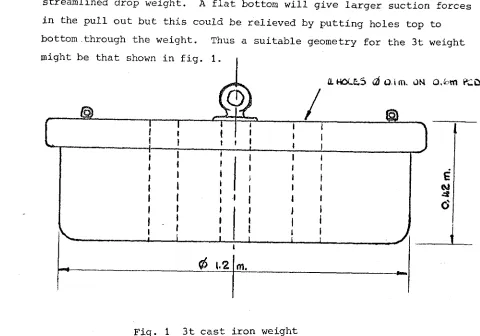
(i) A 3t weight
The volume of cast iron required to give a mass of 3t is 0.417m'
(density of cast iron 7200 kg/m'). To give the maximum impact with
little penetration, a weight with a flat bottom seems desirable.
Reducing the penetration depth will reduce friction forces in the pull
streamlined drop weight. A flat bottom will give larger suction forces
in the pull out but this could be relieved by putting holes top to
bottom through the weight. Thus a suitable geometry for the 3t weight
might be that shown in fig, 1
a.HOLE.5 d Dim. UN o.fcm i^D
I I
• t
I I
0 1.2
m./
E
6
Fig. 1 3t cast iron weight
The construction of such a weight is obviously quite simple but the
major difficulty comes in its handling. A suitable strong point would
have to be found on the ship for its stowage, not too far distant from
the crane davit on the starboard quarter of the rear deck area. Special
arrangements would have to be made for moving the weight from this point
to the davit, possibly using the crane and several restraining lines.
The most vulnerable part of the operation would be deployment and recovery.
Unfortunately, a crane having a rigid arm capable of reaching down the
5 m from deck level to the sea surface and thus restraining the swinging
motion of the weight, is not currently available. A 3t weight could do
serious damage to the stern plates of the ship if unrestrained during
these potentially hazardous phases of the operation.
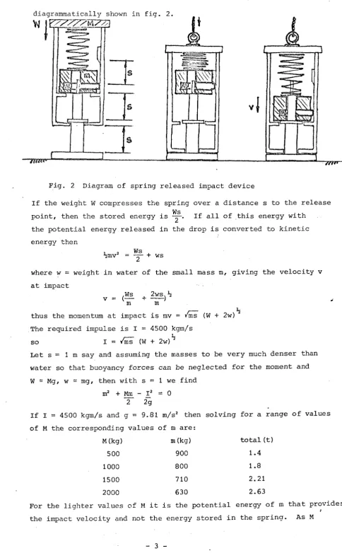
(ii) A spring released impact device
The principle of such a device would be the same as that used in a spring
released centre punch. A spring is compressed storing potential energy
which is released giving kinetic energy to a mass which impacts on the
surface. In order to work repeatedly on the bottom, the simplest method
of compressing the spring would be to use a weight. The system is
[image:5.608.80.560.87.423.2]diagrammatically shown in fig. 2
»awaL
7W7»~
Fig. 2 Diagram of spring released impact device
If the weight W compresses the spring over a distance s to the release Ws
point, then the stored energy is — . If all of this energy with
the potential energy released in the drop is converted to kinetic
energy then
1 2 Ws ^ ^mv = + ws
where w = weight in water of the small mass m, giving the velocity v
at impact
V = ( Ws 2ws, h
4500 kgm/s ,^5
m m
thus the momentum at impact is mv = /ms (W + 2w)
The required impulse is I
so I = i/m^ (W + 2w)
Let s = 1 m say and assuming the masses to be very much denser than
water so that buoyancy forces can be neglected for the moment and
W - Mg, w == mg, then with s = 1 we find
m^ + Mm - I^ - 0 2 2g
If I = 4500 kgm/s and g = 9.81 m/s^ then solving for a range of values
of M the corresponding values of m are:
M(kg) m(kg) total (t)
500 900 1.4
1000 800 1.8
1500 710 2.21
2000 630 2.63
For the lighter values of M it is the potential energy of m that provides
the impact velocity and not the energy stored in the spring. As M
[image:6.598.78.563.34.817.2]-decreases so the device becomes more a controlled free fall of the
mass m. In the extreme case of M = 0, or very small compared with m,
m == It and the velocity is /2gs neglecting drag or 4.4 m/s if s = Im.
This is the case where there is no spring at all, such a device might
look like that shown in fig. 3. Ingenious as this may appear, it is
clear that it will be a very
large device, at least 4 m long
and 1 m or more in diameter. It
would involve some clever engineering
to ensure the release would be
reliable and the drag of the free
fall mass and the damping effect
of the.water inside the casing
would have to be minimised if the
weight were to be able to deliver
its full momentum. It has the
advantages of only weighing perhaps 4m
mass
-rrm
jwwa ,L
f M.
Fig. 3 Free fall mass system
1.5t in air and would be less damaging to the cable than the 3t weight
which would suddenly unload the cable at impact at full payout speed.
This device could be more gently placed on the bottom and the casing
slowly lowered to trigger the impact.
(iii) The water trapping weight
The principle involved here is that if you can get the weight to trap
a large volume of water inside it when descending, then it will have a
high effective mass when it collides with the bottom. To make the
bottom weight significantly lighter than the 3t of example (i) then
the volume trapped will have to be quite large, 1 to 2m^ say, if the
weight is to fall at 1.5 m/s, as dictated by the winch. The advantage
of such a construction is that it will weigh less than 3t in air and
thus reduce handling difficulties. However the advantage gained in
reducing the weight is paid for in increased bulk. An important feature
of such a construction must be the ability to dump water quickly as it
comes out of the water in recovery so that the weight of water does not
have to be lifted by the crane. The reduced weight will also bring
down the tension in the wire through all phases of operation. Having
considered several shapes and designs, the final device might look like
that shown in fig. 4-5. This has an overall weight of 1.5t in air and
would trap 1.45 m^ of water giving an overall mass of approximately 3t.
The bottom weight could be of steel and concrete construction and
-assuming the upper steel container to weigh 200 kg, this would have
to have a mass of 1.3t. Since it stands 2 m high, it may be handled
over the side by the crane davit, although some additional method of
constraint during deployment, recovery and deck handling is still
necessary. The water is trapped during descent by the closing of a
conical valve. This valve could be made of a buoyant material so
that the valve was always closed when submerged or else it could rely
on differential pressure to close it during descent. When falling on
the wire at 1.5 m/s, the internal pressure will build up to near
stagnation pressure, water being forced into the container through
the holes on the bottom face which will be at stagnation pressure.
At 1.5 m/s stagnation pressure is 1.15 kPa (kN/m^), in the wake
behind the valve the pressure will be lower than ambient and this
differential should be sufficient to close a valve fabricated from
3 mm thick steel. The valve travel need not be large, just sufficient
to allow air to rush in and discharge the trapped water as the container
comes through the water surface on recovery. It is estimated that the
drag on such an object travelling at 1.5 m/s might be 160 kg and the
free fall velocity if detached from the wire might be 4 to 5 m/s
depending on its weight in water which may be only It if the base is
constructed using concrete. A 5 cm gap has been left at the bottom of
the container for rapid draining during recovery. Some of the impact
forces of the weight on the side of the ship may be absorbed using
rubber fenders, but some quite substantial structure will have to be
built into the water container to take such loads should they occur.
The base will require reinforcing if made of concrete and the provision
of some inbuilt structure to transmit the weight of the concrete to
the central pole. Steel sheathing may also be necessary to prevent
the concrete from cracking and breaking up on impact with the sea bed.
Penetration depth and pull-out forces
Schmid (1969) gives a variety of formulae for the penetration of objects
into the sea bed, all of which depend upon the bearing capacity of the sediment.
Obviously this will vary very considerably but the worst case will probably
be for soft clays. According to Lee (1974) red clay has an undrained cohesive
shear strength of 7 kPa. The bearing strength for deep-sea cohesive soils
as given by Valent (1974) is
P Q = 5.7 kc
where c is the cohesive shear strength of the sediment and k is a shape factor
-for the object penetrating the soil, k = 1.3 -for a circular footing. This
ves a bearing capacity of = 52 kPa.
For constant area penetration, i.e. a cylinder penetrating the surface
c
by
gives a bearing capacity of = 52 kPa.
Lo
end on, as in the case of the 3t weight, the penetration depth is given
X
max
27rR'P o
where v = velocity at impact, m = mass of the body, R = radius of cylinder.
For the 3t weight (i) this gives x = 6 cm and if applied to the l.St max
weight (iii) x = 5 cm. If the weight (iii) is approximated to that of
a sphere of 1 m radius then if x^^^ < R/4 the penetration of a sphere is
given by
x = V (—-—) ^
max 2TrRP
which gives x = 14 cm. From this point of yiew to minimise penetration
it is obviously better to have a flat bottom than a spherical or conical
bottom i.e. it might be better to alter the shape of the weight in fig. 4
to a cylinder of 1.3 m diameter.
It is evident that the impact penetration depths will be small but it
will be important to pull the weight off the bottom before it has time to
settle under its static loading. The excess pressure built up in the
sediments under the weight will help to push the weight out and reduce
suction forces on the pull out if the weight can be lifted as soon as
possible after impact, otherwise the excess pressure will be dispersed
through the sediments laterally and the weight will gradually settle into
the mud. If the weight is allowed to settle, then the full pull out suction
force will have to be overcome, this suction pressure is usually taken to be
equal to the soil bearing capacity. Thus if frictional resistance on the
sides of the weight can be ignored, a good approximation if the penetration
depth is small, then the pull-out force of the 3t weight is 6t plus its
weight in water (=3t). For the Iht weight, the pull out is It plus its
weight in water (-It), These forces may be alleviated by drilling holes
through the weight to reduce the effect of the suction. In figs 1 and 4,
four 10 cm diameter holes are shown. Suppose each hole reduces the suction
over an area of 30 cm diameter, this would reduce the suction force by l.St.
This indicates that 8 holes would reduce the suction force to perhaps only
1 or 2t but swift action on pulling out the weight before it settled may
reduce pull out forces to zero.
From these calculations, it is clear that the maximum load expected at
the weight hooking point is less than lOt. It is suggested that lOt proof
chain be used immediately above the weight and a lOt weak link to prevent
excessive loading of the coring warp.
Conclusions
The 3t weight (i) is obviously the simplest and therefore likely the cheapest
device. However, its large weight in air is a major disadvantage and could
constitute a major risk to personnel and equipment on the after deck during
manoeuvring operations to and from the crane davit and during deployment and
recovery. Possibly therefore its low cost benefit would be lost in the provision
of special handling equipment to cope with these operations.
The controlled drop weight has the advantage of a lighter weight, 1.5 to 2t,
and it may be less destructive in its treatment of the warp. However, it would
most certainly be the most costly of the three considered to manufacture,
requiring some heavy and yet precise engineering to release a It weight and
take its impact on a stepped shaft. It has more moving parts and, its major
disadvantage, it stands some 4m high. Also being a self-cocking and releasing
mechanism, there is the danger that through mis-handling it could be released
on deck punching a hole through the deck structure. Aesthetically pleasing
though the centre-punch release mechanism may be, it is perhaps impractical
for this use.
The most viable proposal appears to be the third option. A Iht weight
standing 2m high fabricated in steel and concrete weighing perhaps only It in
water. The penetration and pull-out calculations suggest the following
modifications, shown in blue on figs 4 and 5, a flat bottom and another 4
holes through the base. Perhaps also the lower fender should be wrapped
instead around the concrete weight where the highest lateral momentum will
be should the weight begin to pendulum.
Handling a Iht weight, though proportionately easier than a 3t weight, is
still a non-trivial problem. Special handling techniques using the crane-davit
and central crane in conjunction with additional ropes around the ship anchoring
points will have to be devised when the stowage position for the weight has
been allocated. Possibly the central crane used at full extension as a boom
over the stern linked by a strop to the weight could be used to prevent the
weight hitting the stern plates of the ship during the deployment and recovery
phases of the operation. It has to be accepted that the present ability to
handle heavy and bulky equipment off and onto the ship is not ideal but may
be just adequate given a competant crew.
The maximum loads expected to be imposed on the coring warp are 1.5t weight +
7t max. pull out (all holes blocked) + 8t warp @ 6000 m, total 16.5t. It is to
be hoped that the pull out forces by careful operation can be significantly
-reduced for it is doubtful that the coring warp would stand very many
repeated cycles at this maximum level of loading.
References
1. Whitmarsh R.B. unpublished internal note 24.3.1980
A proposal for a simple sea-bed seismic source with
geotechnical implications.
2. Schmid W.E. (1969) The penetration of objects into the ocean bottom
Proc. ASCE Conf. "Civil Eng. in the Oceans II"
-167-208.
3. Lee H.J. (1974) The role of laboratory testing in the determination
of deep-sea sediment engineering properties.
Deep Sea Sediments Ed. Inderbitzen, p 111-127,
pub. Plenum.
4. Valent P.J. (1974) Deep-sea foundations and anchor engineering
Deep Sea Sediments Ed. Inderbitzen, p 245-269,
pub. Plenum.
z.o 3 9 -F-r P - 4 n > o 5 s Tl n
%
§
tf mg
& Z tP r~ r V g v5
z
U' Z q r I/'I VALVE. I i TRAVEL
L
t ?
0»J
IS
o . o s
6ASE. WEI&HT C- /3oo kq m air
AvECAfrvE. DtKjiiT/^ Z95D kg
Volunae. O.US M"
inRucTucL i - t o & H r ^ 2oo kq m a i f
(. s m ^ t t e a l shOiZL -v b r a c i n g )
TEAFFcO kCATTR. VOLUME -3 I. 45 m ^
MA5S cs 14.90
^ 9
k touts 0 0.\
ON O.U. PCC>
X
/ (>
o
V...
o
o
s.
# — r - \
X
y
2u6&cR. FeKLtitS-S.
4H01E6 00-1
ON 0 . t fCD
SECTION A-A
FiCK . 5