Wi-Fi Traffic Enforcement System (WiTE)
Fady W. Gendi1, Tarek K. Refaat1, Amir H. Sadek1, Ramez M. Daoud1, Hassanein H. Amer1, Chahir S. Fahmy1, Omar M. Kassem1, Hany M. ElSayed2
1Electronics Engineering Department, American University in Cairo, New Cairo, Egypt 2Electronics and Communication Department, Cairo University, Giza, Egypt
Email: [email protected], [email protected], [email protected], [email protected], [email protected], [email protected], [email protected], [email protected]
Received December 29, 2012; revised January 27, 2013; accepted February 9, 2013
Copyright © 2013 Fady W. Gendi et al. This is an open access article distributed under the Creative Commons Attribution License, which permits unrestricted use, distribution, and reproduction in any medium, provided the original work is properly cited.
ABSTRACT
This paper proposes a single integrated traffic enforcement system that is able to recognize and report various traffic violations. It consists of a Wi-Fi infrastructure that enables communication between moving vehicles and a central node. Unlike existing solutions, which address single violations, the proposed model encompasses several issues like exceed- ing speed limits, entering a no entry street, car theft, congestion and tolling. OPNET simulations were run to test the Wi-Fi model and define its different characteristics and limitations. A proof-of-concept case was modeled, and the pro- posed architecture succeeded in meeting all design requirements.
Keywords: Wi-Fi; Traffic Enforcement; Vehicular Networking; Vehicle to Infrastructure (V2I); Infrastructure to Vehicle (I2V)
1. Introduction
Traffic enforcement systems are very important imple- mentations of different technologies used worldwide. However, there is no single solution that involves a uni- fied integrated system that is able to enforce all traffic laws. Existing solutions include Radio Frequency Identi- fication (RFID) used for tolling [1], Camera-based used for red light crossing violations [2]. Also, Radars [3], Wireless Magnetic Sensors [4] and Induction Loops are used for speeding violations [5]. There are also Global Positioning System (GPS)-based traffic monitoring tech- nologies; however, such solutions are mainly used for congestion reporting rather than traffic enforcement [6, 7].
Each of the currently available solutions addresses mainly a single violation, requiring a combination of sev- eral solutions to address them all. The lack of a single comprehensive system is the motivation for this study.
This paper proposes an integrated traffic enforcement system that is able to recognize and report various viola- tions using Wi-Fi. The system consists of Wi-Fi access points that connect to Wi-Fi-enabled vehicles in urban environments. Using this system, the access points are able to communicate with the vehicles and using novel algorithms, and the vehicles are able to identify the vari- ous violations and report them to the access point, which
then connects to the local server. The servers and access points are distributed across the city grid. Some of the violations will require real time communication while others will be able to cope with delay. The issues that are addressed by this system are exceeding speed limits, en- tering a no entry street, car theft, congestion and tolling. This study focuses on the feasibility of a system that ad-dresses these issues, presenting several solutions for each problem. It is important to note that while not addressed in this paper, the effects of implementing such a system in a non-free space environment, considering for example fad- ing, are currently being studied.
This paper will introduce a literature survey of the ex- isting traffic enforcement systems in Section 2. Section 3 describes the proposed system. The specific architec- ture shall be discussed in Section 4 and the results of the simulations will be presented in Section 5. Section 6 will conclude the study.
2. Existing Solutions
range of RFID can be several millimeters up to a few meters. It is mostly used for tolling; however, it was re- cently used for traffic management and enforcement [1]. This involves tracking and surveillance. Active RFID tags can also act as readers and can detect multiple tags simultaneously [8].
Another technology used for traffic enforcement is a camera-based traffic enforcement system. This is the most basic and common system, which relies on image pro- cessing for traffic violation detection. Camera-based systems take pictures upon violation, such as red-light- crossing, and then send the image to a processing unit, which recognizes the violation [2]. These systems can be expensive to implement [8].
One speed detection systems is the radar system. Traf-fic radar units send out a wide radar beam, which widens as it travels and can reach widths of hundreds of meters. The radar unit detects the vehicles when the beam bounces back. The speed is calculated using the Doppler shift [3]. Due to the use of low power, radars suffer from detection problems with out-of-range vehicles [3]. Also, they mis- takenly identify violations due to antenna positioning errors [3].
Another system that is used for vehicle detection uses wireless magnetic sensors. It is able to sense road vehicles due to the fact that they have significant amounts of fer- rous metals in the chassis. The wireless magnetic sensors are sensitive, small and immune to environmental factors. When a vehicle passes by the detector, it affects the flux lines of the magnetic fields of the earth, which are then detected [4]. These systems are used in applications such as parking lot space detection. However, a problem occurs when the vehicle does not emit sufficient magnetic fields to be detected by the sensors. Another similar system is the inductive loop system, which consists of a loop, its extension and a detector. When the detector is powered up, electricity will flow through the loop creating a magnetic field that resonates at a constant frequency. When a ve- hicle passes above the loop it increases the resonating frequency. The difference in resonation can also distin- guish between a large vehicle and a compact car [5].
GPS-based systems used for congestion monitoring are also available. Such systems can utilize on-board GPS units or in more recent times, mobile device-based GPS software [6,7]. While the accuracy or resolution of such devices is sufficient for congestion monitoring, it may not be accurate enough for other applications. There is also the problem of available bandwidth, as the currently im-plemented cellular networks may not be able to handle more demanding real-time loads. The lack of suitability of a GPS-based system will also be addressed for each of the proposed violations.
Seeing as none of the previously mentioned solutions can efficiently address all the issues mentioned in the
introduction, a Wi-Fi-based system is proposed next that integrates several of the major traffic enforcement tech- niques using standard protocols [9,10].
3. Proposed System
The main concept behind the system proposed in this paper, Wi-Fi Traffic Enforcement (WiTE), is placing a Wi-Fi card on-board of all vehicles. This card is able to communicate with various Wi-Fi Access Points (APs) in an infrastructure along the roads of a city, where APs will be available at all intersections. These APs can ei- ther be an existing infrastructure or a specifically built infrastructure for the WiTE system. When simulating the system on OPNET Network Modeler [11], a Free Space Wi-Fi environment is used (path loss exponent of 2).
It is critical to note, that a Free Space environment is not an accurate representation of the practical scenario. For that reason, the following section details the coun- termeasures and calculations used in order to build a net- work on OPNET which more realistically represents the practical scenario. Equation (1) is the Free Space propa- gation model (with path loss exponent n = 2). In this case,
n will be left as a variable rather than a constant to enable
modeling of different environments.
4π n
r t t r
P PG G R
(1)
where:
r
P P
: Rx power (W);
t
G
: Tx power (W);
r
G
: Rx gain;
t: Tx gain;
: wavelength (m);
R: distance between Tx and Rx (m);
n: path-loss exponent.
A vehicle speed of 80 Km/h is higher than any vehicle speed allowed in most downtown areas. In most countries the top speed is 60 Km/h and has a 10% acceptable margin of increase (about 48 Km/h in urban environments in Minnesota and 50 Km/h France [12,13]).
Modeling a moving Wi-Fi node at 80 Km/h on OPNET with an assumed transmit power of 1 mW, it was found that the required antenna sensitivity at the receiver was −80 dBm. Plugging these values into Equation (1) [14], the distance needed for a node to stay within the coverage of an AP in order to achieve successful communication was calculated to be 99.47 m. This distance, as a coverage radius, with the speed of 80 Km/h indicated that the time of connecting/disconnecting and sending a single packet was 4.48 s.
the AP coverage area (with a 95% confidence level). The outcome of the experiment showed an AP coverage radius of 98.19 m and connection duration of 4.42 s. These re- sults confirm the previously calculated values.
Whether on OPNET simulations or in an actual im- plementation, the main requirement for the system is that an AP must have a coverage radius of at least 98.19 m, accommodating a maximum vehicle speed of 80 Km/h. This radius can be controlled by two parameters: transmit power and antenna sensitivity. To achieve 98.19 m on OPNET, a transmit power of 1 mW was used with a Rx
sensitivity of −80 dBm. These values shall be recalculated using Equation (1) for different values of n, to determine
the required transmit power and Rx sensitivity in an urban
environment, guaranteeing a 98.19m coverage radius. The values of n used must lie between 3 and 3.5 [15] and the
resulting transmit power and Rx sensitivity must conform
to the Wi-Fi standard.
The distance (radius of 98.19 m), and Pr (receiver sen- sitivity) set to −80 dBm and the wavelength at 2.4 GHz is 0.125 m. From Equation (1), it can be concluded that the harshest path loss exponent representing an urban envi- ronment that could use the WiTE system with the maxi- mum allowable Wi-Fi transmit power of 100 mW (in EU states) is 2.5 [10]. On the other hand, in the United States [16], the maximum allowed power is 1000 mW and this can be achieved in an environment of path loss exponent 2.75.
The previously stated path loss exponents are quite op- timistic and the WiTE system, if proposed for urban en- vironments, must at least be able to perform within a path loss exponent of 3.0.
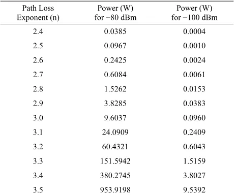
A new technology presented in [17] can deliver sensi- tivity as high as −100 dBm and this value is reused for the calculations. The final set of results, for the highest sen- sitivity available, is shown in Table 1. It can be concluded that using a sensitivity of −100 dBm, a path loss exponent of 3.0 for the EU and 3.254 for the US can be reached.
The next section presents the actual architecture to be used in the WiTE system. The presented architecture is a proof-of-concept with preliminary results, to guarantee feasibility of the system. Effects of fading and interfer- ence are not considered yet but are currently being inves- tigated. The presented system also addresses a scenario where the only Wi-Fi nodes needed are located at the intersections. In many cities, there is widespread Wi-Fi coverage, and it would be even more optimistic.
4. System Architecture
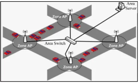
[image:3.595.308.539.111.304.2]The proposed system architecture requires the placement of Wi-Fi APs at traffic junctions and roundabouts. These are linked together using wired Switched Ethernet to “ZONES” representing a small geographical area. These ZONES in turn are connected to larger centers “AREAS”
Table 1. Path loss exponent vs. power needed for −80 dbm and −100 dbm antenna sensitivity.
Path Loss
Exponent (n) for Power (W) −80 dBm for Power (W) −100 dBm
2.4 0.0385 0.0004 2.5 0.0967 0.0010 2.6 0.2425 0.0024
2.7 0.6084 0.0061 2.8 1.5262 0.0153 2.9 3.8285 0.0383
3.0 9.6037 0.0960 3.1 24.0909 0.2409 3.2 60.4321 0.6043
3.3 151.5942 1.5159 3.4 380.2745 3.8027 3.5 953.9198 9.5392
representing larger geographical areas. In turn, all of these AREAS are connected to a central administrative traffic unit that contains the central database with all the vehicles’ records. A simple representation can be seen in Figure 1. These wireless access points transmit a beacon to the vehicles in the intersection or roundabout repeat- edly at fixed intervals. On the receiving end, all vehicles are equipped with a processor, connected to the Wi-Fi card. Each beacon sent from an AP contains traffic regu- lations regarding that area that are received by the vehi- cle processor. This onboard processor uses the beacon packet to monitor the vehicle and report any violations. If a violation takes place, the vehicle immediately sends a packet to the nearest AP, which can then be relayed to the central station and added to the vehicle violations log in the central database.
The WiTE system’s main strength is the integration of several different traffic violations. The violations are monitors and reported by the same system. These are: speeding, no entry, and theft. In addition, solutions for tolling and congestion reporting are also presented. In the AP Beacon, the current AP ID, adjacent 4 AP IDs, vehi-cles allowed to pass and their respective speed, and stolen car IDs are all included. This information takes up less than the smallest Ethernet data payload, 46 bytes. The violation packet is even smaller containing the violation ID, time and date as well as the vehicle and AP ID. The algorithms proposed for each of the different traffic vio- lations supported by the WiTE system are presented be- low.
Speeding Violation
1) A default maximum speed of 60 km/hr is prepro- grammed into all vehicles.
Figure 1. Proposed system architecture.
different vehicle types.
3) This speed limit is updated within the vehicle if it is different from the default 60 km/hr.
4) Vehicle onboard speedometer monitors speed and processing unit continuously monitors speed and com- pares to limit.
5) When the vehicle speed exceeds the limit for a cer- tain duration of time, a violation is logged.
6) The logged violation saves the zone where the vehi- cle was at pre-violation and post-violation, the speed, time, violation ID and vehicle ID.
7) The next zone the vehicle joins, will receive the vio- lation, over TCP/IP. The acknowledgment of receipt will initiate clearing of onboard logged violation. If no ac- knowledgement is received, the vehicle will continue to report the violation.
8) Once successfully received by Zone AP, the viola- tion is forwarded to the central office.
9) Processing is finalized at the central office, logging of data, mapping location, time, date, fine and ID.
To enable the detection of speeding violations, all wireless access point beacons for a certain junction are programmed with a preset maximum speed limit de-pending on the zone.
No Entry Violation
1) Vehicle receives beacon upon entering intersection (i.e., beginning of no entry zone).
2) For this vehicle type, the beacon speed limit data will indicate a speed of zero.
3) Automatically, upon entering the zone, the vehicle will record a violation (if in motion).
4) The violation is reported to the nearest Zone AP to which it connects after violation.
5) Violation contains location, time, date, vehicle type and ID.
6) Again over TCP/IP protocol.
Stolen Vehicle Violation
1) A stolen vehicle is reported by its owner.
2) Be it reported in a certain area or over the entire city, the authorities will utilize the zones that form this area/ city.
3) A section of the beacons sent out, will be reserved for searching for stolen vehicles.
4) If more than 1 vehicle is being searched through the system, Time Division Multiplexing (TDM) will be used. At any given time interval, only one specific vehicle will be searched for.
5) These beacons will be continuously sent until the stolen vehicle replies to an AP, therefore giving its loca- tion.
6) When the vehicle’s internal system reads the packet from the AP and recognizes itself as the stolen vehicle, a certain internal flag is set, which will cause the vehicle to continuously send beacons. This will make the tracking of the vehicle possible. This will only stop when the vehicle is reset (by the authorities).
7) The beacon sent by the vehicle contains a unique ID for tracking purposes. This gives these packets priority over other packets.
8) The AP knows to directly forward these received packets to the central office of the area to notify the au- thorities in real time.
Congestion Monitoring
1) A vehicle in a congested area (e.g., where the speed of the vehicle is 10 Km/h or less for more than 2 minutes) will log its location based on the nearest Zone AP.
2) A congestion packet is sent to the Zone APs as if it was a violation and will await an acknowledgement. At the area level, when the system receives a large number of congestion packets, either authorities will be notified of an issue in the area, or merely a state of traffic congestion will be declared.
3) If an AP receives a packet indicating congestion outside its area, then that AP will forward that information to the station connected with that certain area.
Tolling Usage
1) Entering a toll station, a vehicle receives a beacon from the corresponding station AP, containing location, time and date.
2) At the exit toll station, the car receives the beacon from the exit AP and sends the AP ID and time of entry into the tolled road to the exit AP.
3) Once the exit AP receives the exit message, it sends the AP ID and time of the exit and entry points to the central station.
4) The central station calculates the fare according to the system implemented in the country and bills the ve- hicle ID accordingly.
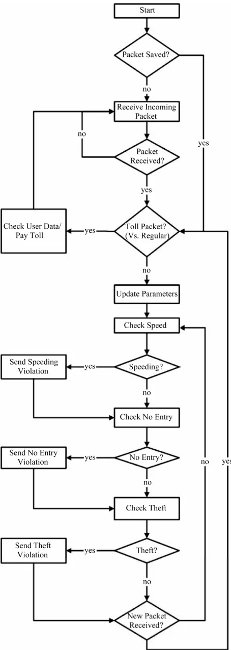
Figure 2. Proposed system algorithm flowchart.
paper. For example, in the case of no entry violations, the accuracy of current GPS systems is not high enough to determine the location (and specifically the lane) of the vehicle. For high path-loss exponents (as previously used in Equation (1)), the GPS signal accuracy deteriorates. Moreover, in the case of theft, due to the lack of a cellular downlink (infrastructure to vehicle communication), a very large overhead will be added for cars to constantly notify the infrastructure of their IDs and locations. The use of the uplink (vehicle to infrastructure communication) for reporting will also congest the cellular network, which is not designed to accommodate this load, affecting net- work subscribers and hence, degrading Quality of Service (QoS).
5. Simulations and Results
To verify the effectiveness and proof-of-concept for the system, several simulations were conducted using OPNET to model the worst-case real life scenarios for the system. The goal was to ensure that the system could withstand the worst conditions, with 95% confidence, and be able to detect all possible violations.
The experiments revolved around two testing criteria: the maximum number of vehicles the AP can withstand (Experiment I) and the maximum speed the data packets (beacons and violations) can be sent and received suc-cessfully (Experiment II).
In Experiment I, the maximum number of vehicles that can simultaneously communicate with one AP at a traffic junction with no delayed or dropped packets according to the predefined data was determined to be 62 vehicles. Based on the delay/drop criteria mentioned, a number of vehicles greater than 62 would not be satisfied, and the AP would not guarantee that all vehicles are able to commu- nicate correctly.
This value was obtained by modeling a basic intersec- tion layout. Vehicles were equally distributed along the four lanes of the intersection. All vehicles are evenly spaced and are all static, simulating a traffic jam.
[image:5.595.317.529.608.723.2]An AP (modeling the Zone AP) is positioned in the middle of the intersection, wired to a switch, and finally to the server (modeling the central office). This layout can be seen in Figure 3. Each of the vehicles is programmed to
report a range of the different violations, to maximize congestion and the number of vehicles is gradually in- creased to determine the maximum number of vehicles that the AP can serve, without violating system require- ments.
In Experiment II, a case study is presented as a proof- of-concept. The experiment is an arbitrarily deployed model of a street, spanning ten intersections with a num- ber of vehicles of varying speeds moving along the street. The main purpose of this experiment is to demonstrate that within a generic example, with miscellaneous viola- tions occurring, all vehicles, including those traveling at high speeds, will achieve two-way communication.
The experiment consisted of 66 vehicles in 6 parallel paths (3 paths heading East and 3 West) with each path having 11 vehicles arranged serially. Each group of 6 vehicles was initially placed at one of the ten Access Points. Each path is assigned a different speed (40 Km/h, 60 Km/h, 80 Km/h). The six parallel paths pass beside ten APs that are equally dispersed and then return to the origin using the same paths. The layout of the experiment can be seen in Figure 4.
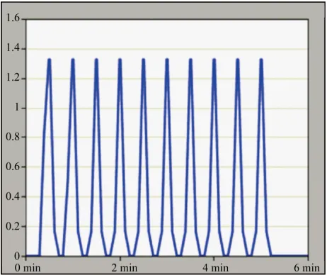
[image:6.595.308.539.84.278.2]Figures 5-7 show the communication undergone by vehicles moving at different speeds in Experiment II. In Figures 5-7, the x-axis is simulation time in minutes and seconds. The y-axis is traffic received in bytes/sec. These
Figure 4. Experiment II layout.
Figure 5. Traffic sent by one of the vehicles (80 Km/h).
[image:6.595.309.538.307.497.2]Figure 6. Traffic sent by one of the vehicles (60 Km/h).
Figure 7. Traffic sent by one of the vehicles (40 Km/h).
graphs indicate that even at the unlikely (and illegal) speed of 80 Km/h in the proposed environment, the vehicle is still able to communicate with each zone AP.
6. Conclusions and Future Work
There are several existing solutions that address different types of traffic violations. These systems incorporate dif- ferent technologies to tackle violations such as speeding, theft, no-entry and other issues. None of the existing sys- tems contain a comprehensive solution that provides lower costs and reduced technical segmentation.
[image:6.595.58.288.527.720.2]single access point (located at intersections) can support up to 62 vehicles in a worst-case scenario. The effects of interference on the system are currently being investi- gated.
REFERENCES
[1] Y. A. Kathawala and B. Tueck, “The Use of RFID for Traffic Management,” International Journal of Technol- ogy, Policy and Management, Vol. 8, No. 2, 2008. doi:10.1504/IJTPM.2008.017215
[2] Road Flow, “Fixed/Static Traffic Enforcement System,” 2011.
http://www.roadflow.co.uk/Traffic_Enforcement_Solutio ns/ROADflow_Fixed.aspx
[3] TIPMRA, “How Speed Trap Radar Works,” 2011. http://tipmra.com/new_tipmra/how_Speed_Trap_Radar_ works.htm
[4] E. Sifuentes, “Wireless Magnetic Sensor Node for Vehi- cle Detection with Optical Wake-Up,” IEEE Sensors Journal, Vol. 11, No. 8, 2011, pp. 1669-1676.
doi:10.1109/JSEN.2010.2103937
[5] MARSH Products Inc, “The Basics of Loop Vehicle De-tection,” 2011.
http://www.marshproducts.com/pdf/Inductive%20Loop% 20Write%20up.pdf
[6] Y. Byon, A. Shalaby and B. Abdulhai, “Travel Time Col- lection and Traffic Monitoring via GPS Technologies,” Proceedings of the IEEE Intelligent Transportation Sys- tems Conference ITSC, Toronto, September 2006. [7] J. C. Herrera, D. B. Work, R. Herring, X. Ban and A. M.
Bayen, “Evaluation of Traffic Data Obtained via GPS-
Enabled Mobile Phones: The Mobile Century Field Ex- periment,” Journal of Transportation Research Part C: Emerging Technologies, Vol. 18, No. 4, 2010.
[8] S. Bandyopadhyay, “Traffic Congestion Management Us- ing RFID & Wireless Technologies,” Indian Institute of Management, Calcutta, 2011.
http://www.intranse.in/its1/sites/default/files/7-Congestio n%20Management-Somprakash.pdf
[9] IEEE 802.3 Std. [10] IEEE 802.11 Std.
[11] Official Site for OPNET Network Modeler. http://www.opnet.com
[12] Minnesota Department of Transportation.
http://www.chico.ca.us/building_development_services/tr affic/speed_limits.asp
[13] “Driving in France, French Monitoring Laws.” http://driving.drive-alive.co.uk/driving-in-france.htm [14] T. S. Rappaport, “Wireless Communications: Principles
and Practice,” 2nd Edition, Prentice Hall, Upper Saddle River, 2002.
[15] T. Chrysikos and S. Kotsopoulos, “Impact of Channel- Dependent Variation of Path Loss Exponent on Wireless Information-Theoretic Security,” Proceedings of the IEEE Wireless Telecommunications Symposium WTS, Prague, April 2009.
[16] Official Site for FCC Regulations. www.fcc.gov
[17] Tropos, “Receive Sensitivity: A Practical Explanation,” 2007.