ISSN Online: 2164-0181 ISSN Print: 2164-0165
DOI: 10.4236/mme.2018.82009 May 15, 2018 121 Modern Mechanical Engineering
An Underactuated Linkage Finger Mechanism
for Hand Prostheses
H. M. C. M. Herath, R. A. R. C. Gopura, Thilina D. Lalitharatne
Bionics Laboratory, Department of Mechanical Engineering, University of Moratuwa, Katubedda, Sri Lanka
Abstract
The underactuated fingers used in numerous robotic systems are evaluated by grasping force, configuration space, actuation method, precision of operation, compactness and weight. In consideration of all such factors a novel linkage based underactuated finger with a self-adaptive actuation mechanism is pro-posed to be used in prosthetics hands, where the finger can accomplish flexion and extension. Notably, the proposed mechanism can be characterized as a combination of parallel and series links. The mobility of the system has been analyzed according to the Chebychev-Grübler-Kutzbach criterion for a planar mechanism. With the intention of verifying the effectiveness of the mechan-ism, kinematics analysis has been carried out, by means of the geometric re-presentation and Denavit-Hartenberg (D-H) parameter approach. The pre-sented two-step analysis followed by a numerical study, eliminates the limita-tions of the D-H conversion method to analyze the robotics systems with both series and parallel links. In addition, the trajectories and configuration space of the proposed finger mechanism have been determined by the motion si-mulations. A prototype of the proposed finger mechanism has been fabricated using 3D printing and it has been experimentally tested to validate its func-tionality. The kinematic analysis, motion simulations, experimental investiga-tions and finite element analysis have demonstrated the effectiveness of the proposed mechanism to gain the expected motions.
Keywords
Linkage Finger Mechanism, Underactuation, Kinematic Analysis, Denavit-Hartenberg Conversion, Geometric Representation
1. Introduction
Progressively, the researchers have developed different robotic fingers with ious functionalities and mechanisms. Such robotic fingers are functional in
var-How to cite this paper: Herath, H.M.C.M., Gopura, R.A.R.C. and Lalitharatne, T.D. (2018) An Underactuated Linkage Finger Mechanism for Hand Prostheses. Modern Mechanical Engineering, 8, 121-139.
https://doi.org/10.4236/mme.2018.82009
Received: January 20, 2018 Accepted: May 12, 2018 Published: May 15, 2018
Copyright © 2018 by authors and Scientific Research Publishing Inc. This work is licensed under the Creative Commons Attribution International License (CC BY 4.0).
DOI: 10.4236/mme.2018.82009 122 Modern Mechanical Engineering
ious applications, for instance prosthetic hands, industrial grippers, surgical ro-bots and scape robot arms. The effectiveness of an artificial finger will depend on its ability to apply an extensive range of grasping forces, generation of precise motion patterns and establishment of a comprehensive configuration space [1]. Furthermore, endurance to external loads while offering a compact and lightweight hardware will be advantageous [2].
Nearly, in the past three decades of period, numerous prosthetic finger me-chanisms have been developed by the use of tendon-based meme-chanisms [3], crossed-bar mechanism [4], belt or gears based mechanisms [5][6], wire driving methods using elastic elements [7], flexible fluidic actuators [8], torsion spring based mechanisms [9][10] and linkage based mechanisms [11][12]. Among all such mechanisms, the tendon driven, and linkage-based mechanisms have been presented a widespread in underactuated prosthetic finger developments. Sig-nificantly, the underactuated mechanisms have the capability to operate with less number of drivers than the degrees of freedom (DoF) of the mechanism [1], which will be beneficial to introduce compact and light weight designs. In con-sideration of tendon-based mechanisms, the tendon ropes are endure for limited tension and can be demonstrated elastic deformation, which may affect the per-formance of the finger. Therefore, the tendon-based underactuated mechanism is mostly suitable for the applications, which has comparatively a less workload, and finger contact force. [1][13]. However, in order to achieve strong grasping forces it may have need of using larger actuators. Conversely, the larger actua-tors will take a higher actuation time. With the intention of overcoming all such issues, Phlernjai et al. have developed two-phase grasping mechanisms with the use of variable gear transmissions, where the fingers move in a high speed prior to contact with the object and a high force after the contact [2]. Most of the un-deractuated fingers are inherent with self-adaptive ability. In 2014, Li et al. have introduced an underactuated finger with first coupled and secondly self-adaptive grasping mode. Those fingers can adaptively grasp objects with different sizes and shapes while its motions during grasping are anthropopathic [14]. Moreover, Belzile et al. have been succeed in developing an optimal design of self-adaptive fingers for proprioceptive tactile sensing [15]. Fascinatingly, the variable stiffness robotic gripper introduced by Yang et al. is composed of two materials, acrylo-nitrile butadiene styrene for the bone segments and shape-memory polymer (SMP) for the finger joints. The SMP joints are exposed to thermal energy and heated above its glass transition temperature (Tg), where the finger joints exhibit very small stiffness bending by an external force. The finger will restore to its original shape due to SMP’s shape recovering stress [16].
DOI: 10.4236/mme.2018.82009 123 Modern Mechanical Engineering
cause to move by the cables, can be made with less in weight since there is no need to place any actuator inside the finger. Subsequently, a self-adaptive actua-tion method is presented.
In the last 150 years, several approaches have been proposed for the calcula-tion of the mobility of the mechanisms. In the second half of the 19th century and the beginning of the 20th century the Chebychev-Grübler-Kutzbach crite-rion for multi-loop mechanisms were set up. Different versions of these formula were proposed all along the 20th century by Dobrovolski (1949-1951), Artobo-levskii (1953) Kolchin (1960) Rössner (1961), Boden (1962), Ozol (1963), Mano-lescu and Manafu (1963), Bagci (1971), Hunt (1978), Tsai (1999) [17]. Signifi-cantly, the criterion can break down for mechanisms with special geometries and particularly for the over-constrained parallel mechanisms [18]. The Cheby-chev-Grübler-Kutzbach criterion explicit the relationship between the mobility and the structural parameters of the mechanism. Moreover, to accomplish pre-cise and controlled motion patterns, the understanding of the kinematics is ex-tremely essential. Chen et al. have presented the kinematic and dynamic charac-teristics of the human finger as a preliminary step towards the development of robotic and prosthetic fingers that imitate the human finger functions [19]. Sev-eral approaches have been deliberated by the researches, in order to analyze the kinematics of the diverse finger mechanisms. For instance, Licheng et al. have considered positional kinematics of the finger at different stages and the kine-matic analysis of the equivalent mechanism of each stage has been carried out, for their fully rotational finger [1]. Furthermore, Screw theory has been used to establish the general kinematic both of series and parallel manipulators. With the aid of screw theory, Hunt et al. have shown that, a workpiece grasped by a fully-in-series manipulator can only lose freedom, while a workpiece grasped by a fully-in-parallel manipulator can only gain freedom [20]. According to the comparison carried out by Rocha et al., the main feature of the screw-based ki-nematic modelling is the uniformity. In addition, screw-based modelling is ad-vantageous in differential kinematics [21]. However, The Denavit-Hartenberg (D-H) approach is more popular and widely adopted in research than the Screw theory [22]-[27]. D-H conventions model has been originally applied into single loop chains but now almost universally applied to open loop serial chains [28].
DOI: 10.4236/mme.2018.82009 124 Modern Mechanical Engineering
develop a prosthetic hand for power grasping applications [29]. By comparing to the existing self-adaptive and underactuated finger mechanisms, which do per-form different grasps such as cylindrical, hook, lateral pinch, tip pinch and pal-mar pinch, the proposed underactuated mechanism has the unique ability to accomplish self-adaptive power grasps with higher finger contact forces [4][29] [30]. In addition to the prosthetics, the proposed finger mechanism can be used to develop robotic or hydraulic grippers for several other applications, i.e. man-ufacturing, surgeries, drones and space operations.
2. Underactuated Linkage Mechanism
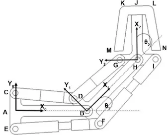
Figure 1 illustrates the schematic diagram of the joints and the links of the lin-kage finger mechanism. Accordingly, the proposed finger mechanism consists of proximal phalanx, intermediate phalanx and distal phalanx which are made of eleven different links. The metacarpophalangeal (MCP) joint of the finger de-noted by point “A” will not be actuated. However the proximal interphalangeal (PIP) joint denoted by point “B”, and distal interphalangeal (DIP) joint denoted by point “H” are designed to be set in rotary motion by any linear actuator, based on active or passive dynamics. The links PPT1, PPT2, PPM, PPB1, PPB2 are placed in the proximal phalanx and IPT1, IPT2, IPM, IPB1, IPB2 are placed in the intermediate phalanx. The link DP act as the distal phalanx. Besides, the rotary joints of the linkage mechanism are pointed out by “C”, “E”, “D”, “B”, “F”, “G”, “H” and “I”. In addition, there are prismatic joints in between C-D, E-F, D-G, and F-I. Accordingly, AB, BH, HJ, CE, DF, GI, LK, GK and IL are fixed lengths where CD, EF, DG and FI are varying lengths. The linear motion of PPB2 towards PPB1, reduces the distance between C-D, which originates a counterclockwise (CCW) rotation on IPM around point “B” (PIP joint). This causes, PPT2 to move away from PPT1 and increase the distance between E-F. Similar way, the linear motion of IPB2 towards IPB1, originates a CWW rotation on DP around point “H” (DIP joint). These CCW rotations result for finger flexion. Contrariwise, the linear motions, PPT2 towards PPT1 and IPT2 towards IPT1, originate clockwise (CW) rotations on IPM and DP around PIP and DIP joints respectively. These CW rotations result for finger extension.
Prototype Finger and Actuation Method
DOI: 10.4236/mme.2018.82009 125 Modern Mechanical Engineering
Figure 1. Links and joints of the linkage finger mechanism.
Figure 2. Design of the prototype finger.
with higher workloads. Elastic rubber loops are placed between PPT1 and PPT2, IPT1 and IPT2. Those rubber loops act as springs to obtain the reverse actuation and bring the finger the initial position. Figure 3 presents the fabricated proto-type of the finger.
Furthermore, a simple hypothesis is proposed, in order to achieve self-adaptive grasping. Figure 4 illustrate the schematic representation of the proposed me-chanism. As shown in the Figure 4, there are two pulleys and one end of the ny-lon string which goes around pulley A is connected to PPB2, where the other end is connected to IPB2. Similarly, the string which goes around pulley B is also connected to PPB2 and IPB2. As there are, two pulleys the forces are equally dis-tributed among the both and it, benefits to reduce the lateral motions. Once the linear actuator generate a motion in the directions shown by arrows, the PIP and DIP joints are supposed to be adjusted adaptively to grasp the object.
3. Kinematics of the Finger
[image:5.595.244.499.239.368.2]DOI: 10.4236/mme.2018.82009 126 Modern Mechanical Engineering
[image:6.595.212.535.193.287.2]Figure 3. Fabricated prototype of the linkage finger mechanism.
Figure 4. Proposed actuation method to accomplish self-adaptive grasps.
Figure 5. (a) Kinematic structure of the prosthetic finger; (b) Simplified kinematic struc-ture for the mobility analysis.
representation of the finger mechanism has been simplified by assuming the middle links act as the bones, where the outer links act as muscles. Figure 5(b) illustrates the simplified kinematic structure for the mobility analysis. By means of the Chebychev-Grübler-Kutzbach criterion for a planar mechanism, the de-gree of freedom (DoF) of the proposed linkage mechanism has been determined by Equation (1).
(
)
1
3 1 j i i
F n j f
=
= − − +
∑
(1)where n is the number of links, j is the number of kinematic pairs and fi is DoF
of the ith pair. For the simplified configuration without length varying links n
equals 3, j equals 2 and Σfi equals 2. Therefore, the effective DoF of the
[image:6.595.213.536.330.418.2]DOI: 10.4236/mme.2018.82009 127 Modern Mechanical Engineering
Figure 6. Geometric representation of the linkage finger mechanism.
lengths. Subsequently, in the second phase, the forward kinematic analysis has been carried out by means of Denavit-Hartenberg (D-H) approach, to determine the positions of the critical points on the finger with respect to the different CD and DG distances.
3.1. Geometric Representation
Figure 6 illustrates the geometric representation for the proposed underactuated finger mechanism. Accordingly, the PIP joint angle is 180 − θ1 and DIP joint
an-gle is 180 − θ2. Rotation angles of the links CD, EF, DG and FIare represented
by α1, β1, α2 and β2 respectively.
According to the geometry, following distances are equal.
AC AE BD BF GH HI= = = = = (2)
Let us consider the links of the proximal phalanx. According the geometry,
1 1
cos sin
EF β −AB BF= θ (3)
1 1
cos sin
AB CD− α =BD θ (4)
By considering, Equation (2), (3) and (4) it can be derived that,
1 1
2AB EF= cosβ +CDcosα (5)
Moreover, according to the geometry it can be established that,
1 1
cos sin
AC BD= θ +CD α (6)
1 1
cos sin
AE BF= θ +EF β (7)
By considering, Equation (2), (6) and (7) it can be derived that,
1 1
sin sin
CD α =EF β (8)
According to the Pythagorean theorem,
(
) (
2)
21 1
sin cos
CD= AB BD−
θ
+ AC BD−θ
(9)DOI: 10.4236/mme.2018.82009 128 Modern Mechanical Engineering
(9) can be simplified as,
2 2 2 2
1 1
sin cos
2
CD AB AC BD AB AC
BD θ θ
− − − = +
− (10)
According to trigonometry it can be derived that,
(
AB)
sinθ1+(
AC)
cosθ1=C1sin(
θ1+δ1)
(11)where;
2 2
1
C =± AB +AC (12)
1 1 tan ACAB
δ
= −
(13)
By substituting to the right hand side of the Equation (10), from Equation (11), (12) and (13),
2 2 2 2
2 2 1
1
sin tan 2
CD AB AC BD AB AC AC
BD θ AB
−
− − − = ± + +
− (14)
Equation (14) can simplified as below to establish a relationship between the angle θ1 and the link lengths.
(
)
2 2 2 2
1 1
1 sin 2 2 tan
2
CD AB AC BD AC
AB
BD AB AC
θ − −
− − − = − − ± + (15)
( )
11 sin A1 1
θ
= − −δ
(16)where;
(
)
2 2 2 2
1 2 2
2
CD AB AC BD
A
BD AB AC
− − −
=
− ± + (17)
1 1 tan
AC AB
δ
= −
(18)
According to the Pythagorean theorem it can be derived that,
(
) (
2)
21 1
sin cos
EF= AB BF+
θ
+ AE BF−θ
(19)By substituting the θ1 from Equation (16), the Equation (19) can be written as,
( )
(
)
(
1)
2(
(
1( )
)
)
21 1 1 1
sin sin cos sin
EF= AB BF+ − A −δ + AE BF− − A −δ (20)
By substituting the θ1 from Equation (16), the Equation (6) can be written as,
( )
(
1)
1 1 1
cos sin sin
AC BD= − A −δ +CD α (21)
Equation (21) can simplified as below to establish a relationship between the angle α1 and the link lengths.
( )
(
1)
1 1
1 1
cos sin
sin AC BD A
CD
δ α
−
− − −
= (22)
DOI: 10.4236/mme.2018.82009 129 Modern Mechanical Engineering
( )
(
1)
1 1 1
cos sin sin
AE BF= − A −δ +EF β (23)
By substituting EF from Equation (20), the Equation (23) can simplified as below to establish a relationship between the angle β1 and the link lengths.
( )
(
)
( )
(
)
(
)
(
(
( )
)
)
1 1 1 11 2 2
1 1
1 1 1 1
cos sin sin
sin sin cos sin
AE BF A
AB BF A AE BF A
δ
β
δ
δ
− − − − − − =+ − + − − (24)
In the same way by considering the links in the intermediate phalanx, it can be proved that the relationship between the angle θ2 and the link lengths are
given by,
(
)
2 2 2 2
1 1
2 sin 2 2 tan
2
DG BH BD GH BD
BH
GH BH BD
θ − −
− − − = − − ± + (25)
( )
12 sin A2 2
θ
= − −δ
(26)where;
(
)
2 2 2 2
2 2 2
2
DG BH BD GH
A
GH BH BD
− − −
− ± +
= (27)
1 2 tan BHBD
δ
= −
(28)
Furthermore, the relationship between the angle α2 and the link lengths are
given by,
( )
(
1)
2 2
1 2
cos sin
sin BD GH A
DG
δ α
−
− − −
= (29)
The relationship between the angle β2 and the link lengths are given by,
( )
(
)
( )
(
)
(
)
(
(
( )
)
)
1 2 2 12 2 2
1 1
2 2 2 2
cos sin sin
sin sin cos sin
BF HI A
BH HI A BF HI A
δ
β
δ
δ
− − − − − − =+ − + − − (30)
3.2. Forward Kinematics
The forward kinematic analysis has been carried out by means of the Dena-vit-Hartenberg (DH) parameter approach. According to the D-H procedure de-scribed by the Rocha et al.[19], first the links and joints should be identified. Links and joints can be numbered from 0 to n. Subsequently, it is required to de-fine the reference frames for the internal links. Then the reference frames should be defined for the extremities links. Successively, the D-H parameters for each link should be identified, where ai is the distance between zi− 1 and zi. di is the
distance between xi − 1 and xi. αi is the angle between zi − 1 and zi measured
along xi, while θi is the angle between xi− 1 and xi, measured along zi. Then the
DOI: 10.4236/mme.2018.82009 130 Modern Mechanical Engineering
Figure 7. Link frame assignment of the linkage finger mechanism for Denavit-Hartenberg analysis.
Table 1. Denavit-Hartenberg link parameters.
Link No. α(i-1) D-H Parameter
(degrees) (mm) a(i-1) (mm) di (degrees) θi
0 0 0 0 0
1 0 AB 0 θ1
2 0 BH 0 θ2
[image:10.595.244.540.446.565.2]the individual joint transformation matrices should be determined. Accordingly, Figure 7 illustrates the link frame assignment of the linkage finger mechanism and Table 1 defines the Denavit-Hartenberg link parameters.
By referring to the link frame assignment and D-H link parameters. The rota-tion around the Z0 axis can be denoted by,
(
)(
) (
)(
)
(
)( )
(
)(
) (
)(
)
(
)( )
0
cos0 sin 0 0 0
sin 0 cos0 cos0 cos0 sin 0 sin 0 0 sin 0 sin 0 cos0 sin 0 cos0 cos0 0
0 0 0 1
T
−
− −
=
(31)
0
1 0 0 0 0 1 0 0 0 0 1 0 0 0 0 1
T
=
(32)
Subsequently, the translation by AB, followed by a rotation around the Z1 axis,
can be denoted by,
(
)(
) (
)(
)
(
)( )
(
)(
) (
)(
)
(
)( )
1 1
1 1
0 1
1 1
cos sin 0
sin cos0 cos cos0 sin 0 sin 0 0 sin sin 0 cos sin 0 cos0 cos0 0
0 0 0 1
AB
T
θ θ
θ θ
θ θ
−
− −
=
(33)
1 1
1 1
0 1
cos sin 0 sin cos 0 0
0 0 1 0
0 0 0 1
AB
T
θ θ
θ θ
−
=
DOI: 10.4236/mme.2018.82009 131 Modern Mechanical Engineering
Successively, the translation by BH, followed by a rotation around the Z2 axis,
can be denoted by,
(
)(
) (
)(
)
(
)( )
(
)(
) (
)(
)
(
)( )
2 2 2 2 1 2 2 2cos sin 0
sin cos0 cos cos0 sin 0 sin 0 0 sin sin 0 cos sin 0 cos0 cos0 0
0 0 0 1
BH T θ θ θ θ θ θ − − − = (35) 2 2 2 2 1 2
cos sin 0 sin cos 0 0
0 0 1 0
0 0 0 1
BH T θ θ θ θ − = (36)
According to the Denavit-Hartenberg convention,
( )
( )( )
0 0 1
2T = 0T 1T 2T (37)
By substituting from the Equation (32), (34) and (36), the Equation (37) can be written as,
1 1 2 2
1 1 2 2
0 2
1 0 0 0 cos sin 0 cos sin 0 0 1 0 0 sin cos 0 0 sin cos 0 0
0 0 1 0 0 0 1 0 0 0 1 0
0 0 0 1 0 0 0 1 0 0 0 1
AB BH
T
θ θ θ θ
θ θ θ θ
− − = (38)
Subsequently, the Equation (38) can be simplified as below,
(
)
(
)
(
1 2)
(
1 2)
10 1 2 1 2 1
2
cos sin 0 cos sin cos 0 sin
0 0 1 0
0 0 0 1
BH AB
BH T
θ θ
θ θ
θ
θ θ
θ θ
θ
+ − + + + + = (39)
The position of the point D with respect to the origin can be defined as,
1
1 0 0 0
1 0 1 1 x y x y z
z D D D T D = (40) where, 1 1 1 0 0 1 1 x y z D BD D D = (41)
Substituting from Equation (34) and (41), the Equation (40) can be written as,
0 0 0
1 1
1 1
cos sin 0 0
sin cos 0 0
0 0 1 0 0
0 0 0 1 1
x y z
AB BD D θ θ θ θ − = (42)
po-DOI: 10.4236/mme.2018.82009 132 Modern Mechanical Engineering
sition of the point D with respect to the origin.
0 0 0
1 1 sin cos 0 1
x y z
BD AB BD D θ θ − + = (43)
Likewise, the position of the point G with respect to the origin can be defined as,
2
2 0 0 0
2 0 2 1 x y x y z
z G G G T G = (44) where, 2 2 2 0 0 1 1 x y z G GH G G = (45)
Substituting from Equation (36) and (45), the Equation (44) can be written as,
(
)
(
)
(
)
(
)
0 0 0
1 2 1 2 1
1 2 1 2 1
0 cos sin 0 cos
sin cos 0 sin
0
0 0 1 0
1
0 0 0 1
x y z
BH AB
GH BH
G
θ θ
θ θ
θ
θ θ
θ θ
θ
+ − + + + + = (46)
Afterwards the Equation (46) can be simplified as below to describe the posi-tion of the point G with respect to the origin.
(
)
(
)
0 0 0
1 2 1
1 2 1
sin cos cos sin
0 1
x y z
GH BH AB
GH BH
G
θ θ
θ
θ θ
θ
− + + + + + = (47)
Successively, the position of the point K with respect to the origin can be de-fined as,
2
2 0 0 0
2 0 2 1 x y x y z
DOI: 10.4236/mme.2018.82009 133 Modern Mechanical Engineering
Substituting from Equation (39) and (49), the Equation (48) can be written as,
(
)
(
)
(
)
(
)
0 0 0
1 2 1 2 1
1 2 1 2 1
cos sin 0 cos sin cos 0 sin
0
0 0 1 0
1
0 0 0 1
x y z
HJ
BH AB
JK BH
K
θ θ
θ θ
θ
θ θ
θ θ
θ
+ − + +
+ +
=
(50)
Furthermore, the Equation (50) can be simplified as below to describe the po-sition of the point K with respect to the origin.
(
)
(
)
(
)
(
)
0 0 0
1 2 1 2 1
1 2 1 2 1
cos sin ) cos sin cos sin
0 1
x y z
HJ JK BH AB
HJ JK BH
K
θ θ
θ θ
θ
θ θ
θ θ
θ
+ − + + +
+ + + +
=
(51)
4. Analysis and Results
The prototype of the linkage finger mechanism has been designed with the link parameters demonstrated in Table 2. By considering the link parameter values and referring to the kinematic analysis, a MatLab program has been developed to plot the positions of the points D, G and K, with respect to the different CD and DG distances. By substituting the values for θ1 and θ2 from Equation (16)
and (26) to Equation (43), (47) and (51) the X and Y coordinates of the points D, G and K have been plotted as illustrated in Figure 8. Furthermore, by substitut-ing link lengths values for the Equation (16) and (26), it has been identified that, during the maximum flexion of the finger, both PIP and DIP joint angles are equal to 134.5˚ where CD and DG distances are at its minimum of 33 mm. Con-trariwise, once the CD and DG equals to 40 mm the finger achieve its maximum extension where PIP and DIP joint angles are equal to 180˚. The configuration space of a finger is its range of movement. A finger can only perform within the confines of this configuration space. As shown in Figure 9, the finger trajecto-ries and the configuration space of the proposed finger in X-Y coordinate system (origin is at MCP joint) has been determined by using the motions simulations inbuilt with Solidworks software package. Based on the finger trajectories and the configuration space, different prosthetic terminal devices can be developed, in order to accomplish the anticipated grasps patterns.
[image:13.595.57.539.671.725.2]Furthermore, experimental investigations have been carried out to confirm the motions of the proposed finger mechanism. Accordingly, the sequence of the finger motions throughout the actuation of the prototype were captured by us-ing a digital camera, as presented in Figure 10. Subsequently, by using the Im-ageJ open source image processing software package [32], the DIP and PIP joint
Table 2. Link parameter values for the prototype finger.
Parameter AC, AE, BD, BF, Constant Variable
GH, HI AB, BH HJ LJ, JK CD, DG EF, FI
DOI: 10.4236/mme.2018.82009 134 Modern Mechanical Engineering
Figure 8. X and Y coordinates of the different finger positions with respect to the CD and DG distance (a) X coordinate of Point D; (b) Y coordinate of Point D; (c) X coordinate of Point G; (d) Y coordinate of Point G; (e) X coordinate of Point K; (f) Y coor-dinate of Point K.
DOI: 10.4236/mme.2018.82009 135 Modern Mechanical Engineering
[image:15.595.208.538.315.465.2]Figure 9. Trajectories and the configuration space of the linkage finger me-chanism.
Figure 10. Sequence of the finger motions with respect to change of both CD and DG distances.
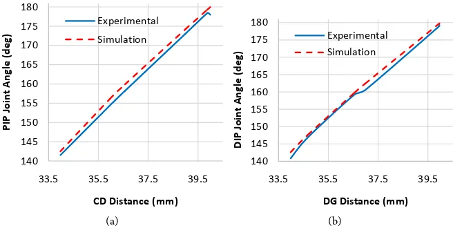
(a) (b)
Figure 11. Comparison between the experimental measurements and motion simulation results for link lengths and joint angles (a) PIP joint angle against CD distance; (b) DIP joint angle against DG distance.
140 145 150 155 160 165 170 175 180
33.5 35.5 37.5 39.5
PI
P J
oin
t A
ng
le
(d
eg)
CD Distance (mm) Experimental Simulation
140 145 150 155 160 165 170 175 180
33.5 35.5 37.5 39.5
DI
P J
oin
t A
ng
le
(d
eg)
[image:15.595.210.538.515.680.2]DOI: 10.4236/mme.2018.82009 136 Modern Mechanical Engineering
Figure 12. Convergence of the finite element analysis.
The finite element analysis (FEA) by Solidworks simulations proved that the finger is sturdy to withstand the standard finger forces. Designed prosthetic fin-ger mechanism is expected to carry 20 N payload at distal phalanx. In addition to the play load it is assumed that 5 N is applied by the elastics rubber loops as a spring effect. Further the tension of nylon strings has been is taken as 10 N where it applies a pull on PPB2 and IPB2. Von misses stress, resultant displace-ment and equivalent strain of the finger have been determined by FEA. Accord-ing to the results, the designed fAccord-inger has a maximum von Mises Stress of 3.36e+007 N/m2, maximum resultant displacement of 1.55 mm and maximum
equivalent strain of 0.008 where the Yield strength, Tensile strength and Elastic modulus of the material (PLA) are 7e+007 N/m2, 7.3e+007 N/m2, 3.5e+009 N/m2
respectively. The minimum factor of safety has been determined as 2. The con-vergence analysis has been carried out for randomly chosen mesh sizes and the results are presented in Figure 12. According to the polynomial curve, the re-sults are converging.
5. Conclusion
DOI: 10.4236/mme.2018.82009 137 Modern Mechanical Engineering
the systems, which are developed as a hybrid of series and parallel links. Fur-thermore, the experimental investigation has verified the functionality of the finger and the exactitude of the analysis carried out. The outcomes of the kine-matic analysis, establishment of the trajectories and the configuration space for the proposed mechanism, will be beneficial for future research towards develop-ing control algorithms for the fdevelop-inger actuation.
Acknowledgements
The authors are indebted to the Department of Mechanical and Manufacturing Engineering, University of Ruhuna, Sri Lanka, for providing the fabrication fa-cilities.
References
[1] Wu, L.C., Kong, Y.X. and Li, X.L. (2016) A Fully Rotational Joint Underactuated Finger Mechanism and its Kinematics Analysis. International Journal of Advanced Robotic Systems, 13, 1-9. https://doi.org/10.1177/1729881416663373
[2] Phlernjai, M., Takayama, T. and Omata, T. (2016) Passively Switched Cable-Driven Transmission for High-Speed/High-Force Robot Finger. Advanced Robotics, 30, 1559-1570. https://doi.org/10.1080/01691864.2016.1251336
[3] Rossi, C. and Savino, S. (2013) Mechanical Model of A Single Tendon Finger. AIP Conference Proceedings, 1558, 1286-1292. https://doi.org/10.1063/1.4825746 [4] Bandara, D.S.V., Gopura, R.A.R.C., Brunthavan, G.K.M. and Abeynayake, H.I.M.M.
(2014) An Under-Actuated Mechanism for A Robotic Finger. Proceedings of the
4th Annual IEEE International Conference on Cyber Technology in Automation Control and Intelligent Systems, Hong Kong, 407-412.
https://doi.org/10.1109/CYBER.2014.6917498
[5] Liu, H., Meusel, P., Hirzinger, G., Jin, M., Liu, Y. and Xie, Z. (2008) The Modular Multisensory DLR-HIT-Hand: Hardware and Software Architecture. IEEE/ASME Transactions on Mechatronics, 13, 461-469.
https://doi.org/10.1109/TMECH.2008.2000826
[6] Koganezawa, K. and Ishizuka, Y. (2008) Novel Mechanism of Artificial Finger Us-ing Double Planetary Gear System. Proceedings of the 2008 IEEE/RSJ International Conference on Intelligent Robots and Systems, Nice, 3184-3191.
https://doi.org/10.1109/IROS.2008.4650589
[7] Kamikawa, Y. and Maeno, T. (2008) Underactuated Five-Finger Prosthetic Hand Inspired by Grasping Force Distribution of Humans. Proceedings of the 2008
IEEE/RSJ International Conference on Intelligent Robots and Systems, Nice, 717-722. https://doi.org/10.1109/IROS.2008.4650628
[8] Gaiser, I.N., Pylatiuk, C., Schulz, S., Kargov, A., Oberle, R. and Werner, T. (2009) The FLUIDHAND III: A Multifunctional Prosthetic Hand. Journal of Prosthetics and Orthotics, 21, 91-96. https://doi.org/10.1097/JPO.0b013e3181a1ca54
[9] Wu, L., Carbone, G. and Ceccarelli, M. (2009) Designing an Underactuated Me-chanism for a 1 Active DOF Finger Operation. Mechanism and Machine Theory, 44, 336-348. https://doi.org/10.1016/j.mechmachtheory.2008.03.011
Medi-DOI: 10.4236/mme.2018.82009 138 Modern Mechanical Engineering
cine and Biology Society (EMBC), Chicago, 6195-6198. https://doi.org/10.1109/EMBC.2014.6945044
[11] Choi, K.Y., Akhtar, A. and Bretl, T. (2017) A Compliant Four-Bar Linkage Mechan-ism that Makes the Fingers of a Prosthetic Hand More Impact Resistant. Proceed-ings of the 2017 IEEE International Conference on Robotics and Automation, Sin-gapore, 6694-6699.https://doi.org/10.1109/ICRA.2017.7989791
[12] Resnik, L., Klinger, S.L. and Etter, K. (2014) The DEKA Arm: Its Features, Functio-nality, and Evolution during the Veterans Affairs Study to Optimize the DEKA Arm. Prosthetics and Orthotics International, 38, 492-504.
https://doi.org/10.1177/0309364613506913
[13] Ceccarelli, M. (2004) Fundamentals of Mechanics of Robotic Manipulation. Sprin-ger Science & Business Media, Berlin.https://doi.org/10.1007/978-1-4020-2110-7 [14] Li, G., Zhang, C., Zhang, W., Sun, Z. and Chen, Q. (2014) Coupled and
Self-Adaptive Under-Actuated Finger with a Novel S-Coupled and Secondly Self-Adaptive Mechanism. Journal of Mechanisms and Robotics, 6, 1-10.
https://doi.org/10.1115/1.4027704
[15] Belzile, B. and Birglen, L. (2017) Optimal Design of Self-Adaptive Fingers for Pro-prioceptive Tactile Sensing. Journal of Mechanisms and Robotics, 9, 1-11. https://doi.org/10.1115/1.4037113
[16] Yang, Y., Chen, Y., Wei, Y. and Li, Y. (2016) Novel Design and Three-Dimensional Printing of Variable Stiffness Robotic Grippers. Journal of Mechanisms and Robot-ics, 8, 1-15.https://doi.org/10.1115/1.4033728
[17] Gogu, G. (2005) Chebychev-Grübler-Kutzbach’s Criterion for Mobility Calculation of Multi-Loop Mechanisms Revisited via Theory of Linear Transformations. Euro-pean Journal of Mechanics—A/Solids, 24, 427-441.
https://doi.org/10.1016/j.euromechsol.2004.12.003
[18] Dai, J.S., Huang, Z. and Lipkin, H. (2004) Mobility of Overconstrained Parallel Mechanisms. Journal of Mechanical Design, 128, 220-229.
https://doi.org/10.1115/1.1901708
[19] Chen, F.C., Appendino, S., Battezzato, A., Favetto, A., Mousavi, M. and Pescarmo-na, F. (2014) Human Finger Kinematics and Dynamics. New Advances in Mechan-isms Transmissions and Applications, Springer, Berlin, 115-122.
https://doi.org/10.1007/978-94-007-7485-8_15
[20] Hunt, K.H., Samuel, A.E. and McAree, P.R. (1991) Special Configurations of Mul-ti-Finger Multi-Freedom Grippers-A Kinematic Study. The International Journal of Robotics Research, 10, 123-134.https://doi.org/10.1177/027836499101000204 [21] Rocha, C., Tonetto, C. and Dias, A. (2011) A Comparison between the
Dena-vit-Hartenberg and the Screw-Based Methods Used in Kinematic Modeling of Ro-bot Manipulators. Robotics and Computer-Integrated Manufacturing, 27, 723-728. https://doi.org/10.1016/j.rcim.2010.12.009
[22] Corke, P.I. (2007) A Simple and Systematic Approach to Assigning Dena-vit-Hartenberg Parameters. IEEE Transactions on Robotics, 23, 590-594.
https://doi.org/10.1109/TRO.2007.896765
[23] Singh, S., Singla, A., Singh, A., Soni, S. and Verma, S. (2016) Kinematic Modelling of a Five-DoFs Spatial Manipulator Used in Robot-Assisted Surgery. Perspectives in Science, 8, 550-553.https://doi.org/10.1016/j.pisc.2016.06.017
DOI: 10.4236/mme.2018.82009 139 Modern Mechanical Engineering [25] Du, Z., Yang, W. and Dong, W. (2015) Kinematics Modeling of a Notched
Conti-nuum Manipulator. Journal of Mechanisms and Robotics, 7, 1-9. https://doi.org/10.1115/1.4028935
[26] Boscariol, P., Gasparetto, A., Scalera, L. and Vidoni, R. (2017) Efficient Closed-Form Solution of the Kinematics of a Tunnel Digging Machine. Journal of Mechanisms and Robotics, 9, 1-13.https://doi.org/10.1115/1.4035797
[27] Li, J., Yu, L.D., Sun, J.Q. and Xia, H.J. (2013) A Kinematic Model for Parallel-Joint Coordinate Measuring Machine. Journal of Mechanisms and Robotics, 5, 1-4. https://doi.org/10.1115/1.4025121
[28] Lipkin, H. (2005) A Note on Denavit-Hartenberg Notation in Robotics. Proc. ASME International Design Engineering Technical Conferences and Computers and In-formation in Engineering Conference, Long Beach, 24-28 September 2005, 921-926. https://doi.org/10.1115/DETC2005-85460
[29] Herath, H.M.C.M., Gopura, R.A.R.C. and Lalitharatne, T.D. (2017) Prosthetic Hand with a Linkage Finger Mechanism for Power Grasping Applications. IEEE Life Sciences Conference, Sydney, 304-307.https://doi.org/10.1109/LSC.2017.8268203 [30] Gopura, R.A.R.C., Bandara, D.S.V., Gunasekera, N.P.A., Hapuarachchi, V.H and
Ariyarathna, B.S. (2017) A Prosthetic Hand with Self-Adaptive Fingers. 3rd Inter-national Conference on Control, Automation and Robotics, Nagoya, 269-274. https://doi.org/10.1109/ICCAR.2017.7942701
[31] Abeysekera, J. and Sha, H. (1987) Body Size Data of Sri Lankan Workers and Their Variability with Other Populations in the World: Its Impact on the Use of Imported Goods. Journal of Human Ergology, 16, 193-208.