Analysis and Control of Solar-Wind Power Generation
System using MATLAB Software
Krishan Kumar
Electrical Egg. Dept. Gautam buddha University
Greater Noida, India
M. A. Ansari
Electrical Egg. Dept. Gautam buddha University
Greater Noida, India
Shreya Singh
Electrical Egg. Dept. Gautam buddha University
Greater Noida, India
ABSTRACT
This paper presents a solar – wind hybrid system modelling with a storage system that provided backup for the system. The main aim is to maintain the power supply continuity to the load of 10 kW which is followed by an inverter and a DC bus. A Simulink model of the hybrid system is developed to study its behaviour under different conditions. The conditions have been assumed in order to show the variation of output at the DC bus and the load with varying the input parameters. The switching between the three systems has been done effectively in order to eliminate discontinuous power supply. For minimum output required, the proper controlling of all the three systems has been done. The power electronics interfacing is also required for conversion of ac to dc and dc to ac.
Keywords
Solar photovoltaic, Wind energy, renewable power system, Hybrid power generation.
1.
INTRODUCTION
The world is facing a constant reduction in fossil fuel, due to high dependency of power generation using the conventional methods in the past years. The world needs some alternate energy sources to meet the present demands. Due to the present environmental conditions, there is also the need of some clean energy sources to decrease the environmental impacts [1].
The conventional sources of energy which includes coal, natural gas, petroleum, etc. have been used on large scale in the past years which has led to its depletion, in addition to this, they have also added to several environmental problems such as coal; one of the majorly used conventional fuel, when burnt releases carbon dioxide, carbon monoxide and soot (carbon particles) which pollute air, it can also cause health hazards for workers in the mine. Power generation using solar energy is being considered as one of the best alternatives these days, but reliability being the major concern in power supply. To improve the reliability of the system, moving towards hybrid system is most important. So solar and wind hybrid system can be considered due to their complimentary nature [2].
Hybrid systems are given more preference as compared to individual renewable sources due to reliability factor. As most of the current renewable energy sources are dependent on weather conditions, therefore their generation becomes uncertain at times, this is the reason we go for hybrid systems. The main advantage of hybrid system is that even if one gets faulty or unable to generate due to the present weather conditions the other can supply in the time being which ensures continuous power supply. Such hybrid systems are
used as standalone systems to provide power to remote areas, rural areas [3].
[image:1.595.322.549.295.475.2]The year wise installed capacity of wind and solar energy is shown in figure 1 and 2 respectively and shows the percentage increment in total energy production year by year.
Fig. 1: Year wise installed capacity of wind energy [4]
Fig. 2: Year wise installed capacity of solar energy [4]
It has been observed that during summer when there is sufficient sunlight the wind speed is generally low whereas during winter the sunlight is less and the wind speed is strong; this variation arises due to their different peak operating times throughout the year.
The complementary nature of wind and solar determines the advantages and potentiality of hybrid power generation systems [5]. So, solar-wind hybrid systems are being used as standalone units and also along with the grid due to their various advantages.
The PV system gets powered by the energy from the sun and this energy is converted into electrical energy using
242
6
1
5
.2 11
1
1
.7 171
6
.1
7
1
7
4
2
.0
5
1
6
6
3
.3
2
1
4
8
4
.9
1
5
6
4
.6 23
4
9
.2 31
9
6
.7
1
6
9
8
.8
2
0
8
9
.9
2
2
9
7
.9
3
4
7
1
.9
5
MW
YEAR
2 2 10 37 481
1446
2647 3062
4879
MW
2 photovoltaic effect whereas the wind energy conversion
system (WECS) uses the kinetic energy of the wind and with the help of generator and other components converts it into electrical energy. Both solar and wind are weather dependent and thus, it is beneficial to use them together as they are both complimentary to each other as has been noticed [6].
Solar-PV (Photo-Voltaic) array and WECS (Wind Energy Conversion System) are gaining attention due to their environment friendly nature, low cost and availability for rural applications [7].
In this paper, a Photovoltaic (PV)/Wind Turbine (WT) system along with a battery has been carried out using MATLAB/Simulink. The switching of the three systems has also been done to show their different operating time according to requirement.
2.
SYSTEM DESCRIPTION
The proposed hybrid system, consists of three different power sources: PV system, Wind Energy Conversion System (WECS) and a storage system (battery). The block diagram of the proposed system is shown below in figure 3.
P
o
w
er
M
an
ag
em
en
t S
ch
em
e
Load
Wind
Solar
[image:2.595.312.507.130.243.2]Battery
Fig. 3: Block diagram of solar-wind hybrid system
2.1.
Modelling of the PV module
To obtain the generalized equation of solar cell, the general mathematical model is used [8,9] and the circuit diagram of a single diode solar cell is shown in figure 4 as:
Rs
Rsh Ipv Load
Id Iph
+
[image:2.595.60.277.313.508.2]_
Fig. 4: Basic circuit diagram of a solar cell
Where, Iph = Photocurrent
Rs = Series Resistance
Rsh = Shunt Resistance
Io = Leakage current
Ipv = Output current of PV module
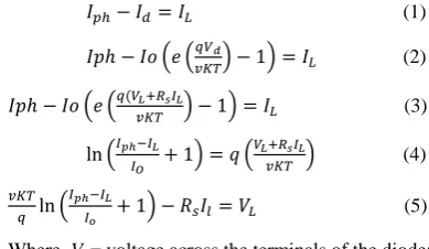
The desired voltage and current for solar array, each cells are arranged to make module and the modules are arranged such that it make an array and fulfill the power requirement. Basic modelling of a solar cell [2] is shown in the following equations as:
(1)
(2)
(3)
(4)
(5)
Where, VL= voltage across the terminals of the diode;
q = absolute value of electron charge; K= Boltzmann's constant; and T= absolute temperature (oK).
I = Ideality factor. It differs from diode to diode.
With the help of MATLAB/SIMULINK, these equations are implemented for making solar module. For the simulation of the PV module “Astronergy CHSM6610P” has been considered. In the proposed model, 14 numbers of module in four parallel string is used for fulfil the load requirement. Each module has the following specification [10] in the table 1 under standard. The different controlling part and converter parts are also described.
Table 1: Specification of system
Parameters Value
Maximum Power (Pm) 225 W
Open Circuit Voltage 36.88 V
Voltage at Pm 29.76 V
Short circuit current(Isc) 8.27 A Current at Pm (IMPP) 7.55 A
Temperature coefficient for Pm -0.46 %/oC
Temperature coefficient for Voc -0.129 V/ oC
Temperature coefficient for Isc +0.052 %/oC
2.1.1.
MPPT
MPPT is a technique which is generally used for controlling power in photovoltaic system. The solar cell gives a non-linear characteristic when different cell temperature and irradiance are taken, as is analyzed by the I-V graph of a PV module. So, MPPT algorithm is implemented which maintain maximum output power irrespective of the changing environmental conditions [11]. To obtain the maximum power output different algorithm can be considered according to requirement. The Perturb and Observe algorithm is used for obtaining the maximum power. The algorithm is work on the value of PV current (Ipv) and voltage (Vpv) by which the duty cycle (D) is increase or decrease accordingly to get the maximum power point.
2.1.2.
Boost Converter
[image:2.595.65.266.584.664.2]level, the duty cycle of the boost converter is controlled using the Perturb and Observe algorithm [12]. In the proposed model the output of the boost converter is given to a dc bus whose voltage has to be maintained at 400V.
2.2.
Modeling of the wind turbine
The wind turbine is modeled using MATLAB/Simulink using the following equations [13]:
(6)
(7)
1
C
toC
6are parameters depending on the blade and rotor design of the wind turbine.
(8)
In the above equations:
= Mechanical Power output of the turbine = Coefficient of performance
Λ = Tip speed ratio β = Blade pitch angle
= wind speed
The wind speed is varied to show natural environmental conditions. The output of the wind turbine is mechanical torque which is dependent on the wind speed and the generator speed. As the wind speed is constantly varying, thus an induction generator which is asynchronous in nature is used. The output torque of the wind turbine is used to move the shaft of the induction generator.
The induction generator chosen is a squirrel-cage induction generator of nominal power of 200 HP. According to Betz’s limit, the maximum kinetic energy that can be captured by a wind turbine is 59.3%. Thus, the efficiency of a wind turbine is quite low and the output is prone to fluctuations due to the varying wind speed.
2.2.1.
Controlling of WECS
As the speed of the wind is continuously varying, so the output power of the generator experiences fluctuations a double bridge rectifier is used for smooth dc output voltage. For less harmonics PWM techniques is used and PI controller is also used to give appropriate firing angles to the PWM generator. The six ports of the double bridge rectifier are provided by an isolation transformer [14].
2.3.
Hybrid system
In the proposed model, two systems (PV and WECS) are used to form a hybrid system and the output of the hybrid system is given to the dc bus and maintained the dc bus voltage (400 V). When the loads are connected, then according to the availability the switching is done and turn on the system along a storage system to maintain the bus voltage. If the PV system is not supply the appropriate power then WECS and storage system to maintain the bus voltage, and if the wind energy is not present in this case PV and storage system both provided the power to the loads. When wind energy and PV both are not contribute in the hybrid system then only storage system is providing all power requirement to the loads. When the load is less and the output power from wind and PV system is higher, in this case the surplus power is used to charge the storage system.
2.4.
Storage system (Battery)
[image:3.595.316.506.465.679.2]For the backup system a battery bank is used. Due to the cost effectiveness and low self-discharging property, a lead-acid type of battery is chosen [15]. The battery is connected to the bus using a bidirectional switch, when dc bus is required power then the battery supply it and when the excess power on the bus then the battery is charge. The specifications of the battery are chosen such that it is able to provide the load (10 kW) for sufficient amount of time.
Table 2: Specifications of the battery
Battery Type Lead-acid
Nominal Voltage (V) 400
Discharge current (A) 35
Capacity (Ah) 25
Initial SOC (%) 90
2.5.
Switching of the hybrid system
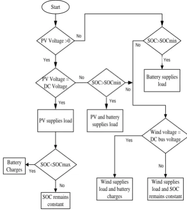
The switching between the three systems is done in order to maintain the continuity in power supply to the load. The irradiance of the PV rises and falls during the course of a day. The simulation is done for a lesser time, thus variations in the irradiation is assumed with its peak at 1000 W/m2 and lowest being 0 W/m2. The time during which the irradiation falls, the PV fails to maintain the bus voltage and thus until the irradiance become 0 W/m2, the supply is accompanied by battery (the battery’s SOC falls and it supplies the load) [16-20].
When the WECS voltage builds up and is capable of providing the load it takes over from the battery and provides the load and charges the battery until the SOC reaches its initial state of charge. The flow chart of the controlling algorithm is shown in figure 5 as below.
Start
PV Voltage >0
PV supplies load
Battery Charges
SOC remains constant
PV and battery supplies load
Battery supplies load
Wind supplies load and battery
charges
Wind supplies load and SOC remains constant PV Voltage =
DC Voltage
SOC>SOCmin
Wind voltage = DC bus voltage SOC>SOCmin
SOC<SOCmax No
No
No No
No
No
Yes Yes
Yes Yes
Yes
Yes
Fig. 5: Flow chart of switching sequence algorithm
3.
INPUT IRRADIATION FOR PV
4 second and then increase and irradiation becomes 1000 w/m2
[image:4.595.314.540.77.200.2]as shown in figure 6. The temperature is maintained at 25o C.
Fig. 6: Solar irradiation with time
4.
RESULTS AND DISCUSSION
The whole switching is grouped into different modes with the help of sampling time.
In the first mode, sample time [0, 0.024] the solar voltage will be building up thus for the time being the battery will provide to the bus. Once the steady state is achieved by the PV, in the second mode with sample time of [0.024, 0.25] the PV will maintain the bus voltage and will also charge the battery. The load is connected at time (t) = 0.08 s when the PV is able to provide the load. Initially PV will provide the load.
Fig. 7: Output of the Boost Converter
The output of the boost converter is shown in figure 7, which varies according to the irradiance level as shown in figure 6. In the third mode of sample time [0.2, 0.35], the irradiance starts falling and to supply the load and to maintain the bus voltage the battery starts discharging. At t = 0.035s, the irradiance totally becomes 0 W/m2.
[image:4.595.55.280.101.248.2]In the fourth mode, of sample time [0.4, 0.56], the SOC of the battery falls below a certain level, and then the WECS gets connected to the load and maintains the bus voltage to approximately 400 V and also charges the battery.
Fig. 8: Output of the Wind Energy Conversion System
[image:4.595.319.547.329.474.2]The output voltage of wind turbine is shown in figure 8, the output voltage is maintained at around 400 V but due to switching transients some fluctuations can be seen. In the fifth mode, of sample time [0.6, 1.1] again solar irradiance rises to 1000 W/m2 and the load will again be provided by the PV and the battery will also be charged. At t = 1.1 s the load gets disconnected. The SOC of the battery is shown in figure 9, the charging and discharging is taken for a small interval of time, thus linear variation is also visible.
Fig. 9: SOC of the Battery
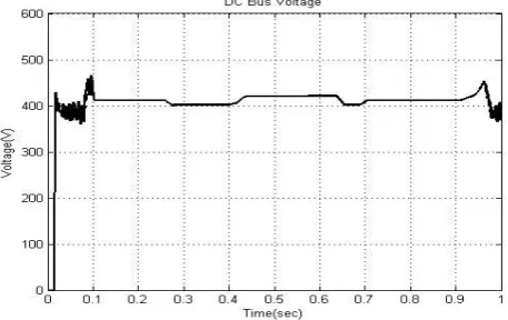
The DC bus voltage is tried to be maintained at 400 V by different sources that can be supply power on different time so the fluctuates in the bus voltage is present due to switching transients, as seen in figure 10 below.
[image:4.595.53.282.390.514.2] [image:4.595.317.546.541.685.2]5.
CONCLUSION
In this paper, solar-wind hybrid system is presented, it is an effective combination when subjected to changing environmental conditions. The WECS is operated for lesser amount of time only when PV fails to provide the required power to the system. The storage device is used to help for continuous power, when either the voltage is building up or falling down to the desired voltage level for maintaining constant power supply.With the help of appropriate switching of these sources the output power of the system is maintain to required power. The synchronization of these three systems i.e. WECS, solar PV and storage system, play an important role for continuous power supply.
6.
REFERENCES
[1]. Twidell, John, and Tony Weir. Renewable energy resources. Routledge, 2015.
[2]. Khare, Vikas, Savita Nema, and Prashant Baredar. "Solar–wind hybrid renewable energy system: A review." Renewable and Sustainable Energy Reviews 58 (2016): 23-33.
[3]. Patel, Mukund R. Wind and solar power systems: design, analysis, and operation. CRC press, 2005.
[4]. http://www.cea.nic.in/reports/annual/annualreports/annua l_report-2015.pdf
[5]. Jian, Chen, Che Yanbo, and Zhao Lihua. "Design and research of off-grid wind-solar hybrid power generation systems." Power Electronics Systems and Applications (PESA), 2011 4th International Conference on. IEEE, 2011.
[6]. Adhikari, Neha, et al. "Analysis, design and control of a standalone hybrid renewable energy conversion system." Power Electronics for Distributed Generation Systems (PEDG), 2013 4th IEEE International Symposium on. IEEE, 2013.
[7]. K. Kumar and M. A. Ansari, “Evaluation of Power Management Strategy for Renewable Microgrid System”, Indonesian Journal of Electrical Engineering and Informatics (IJEEI), vol. 6, no. 2 (2018): 133-142. [8]. Shongwe, Samkeliso, and Moin Hanif. "Comparative
analysis of different single-diode PV modeling methods." IEEE Journal of Photovoltaics 5.3 (2015): 938-946.
[9]. Bellia, Habbati, Ramdani Youcef, and Moulay Fatima. "A detailed modeling of photovoltaic module using MATLAB." NRIAG Journal of Astronomy and Geophysics 3.1 (2014): 53-61.
[10].K. Kumar and M. A. Ansari, “Design and development of hybrid wind-hydro power generation system.” Energy
Efficient Technologies for Sustainability (ICEETS), 2013 International Conference on. IEEE, 2013.
[11].Abo-Khalil, Ahmed G., et al. “Maximum power point tracking controller connecting PV system to grid.” Journal of Power Electronics 6.3 (2006): 226-234. [12].Fathabadi, Hassan. "Novel high efficiency DC/DC boost
converter for using in photovoltaic systems." Solar Energy 125 (2016): 22-31.
[13].K. Kumar, M.A. Ansari, S. K. Varshney, Vinay Rana, and Arjun Tyagi. "An Efficient Technique for Power Management in Hybrid Solar PV and Fuel Cell System.” Smart Science, vol. 6, no. 3 (2018): 234-244. [14].Natsheh, Emad M., Alhussein Albarbar, and Javad
Yazdani. "Modeling and control for smart grid integration of solar/wind energy conversion system." Innovative Smart Grid Technologies (ISGT Europe), 2011 2nd IEEE PES International Conference and Exhibition on. IEEE, 2011.
[15].Lee, Dong-Jing, and Li Wang. "Small-signal stability analysis of an autonomous hybrid renewable energy power generation/energy storage system part I: Time-domain simulations." IEEE Transactions on Energy Conversion 23.1 (2008): 311-320.
[16].Farheen, M. A. Ansari and Neha Kardam, “Implementation of Particle Swarm Optimization for Dynamic Economic Load Dispatch Problem”, Proc. of the IEEE Int. Conf. on Energy Efficient Technologies for Sustainability (ICEETS’13), Page(s): 1273 – 1278, 10– 12 April 2013.
[17].Vinaya Rana and M. A. Ansari, “Wind Farm Integration Effect on Electricity Market Price”, Proc. of the IEEE International Conference on Energy Efficient Technologies for Sustainability (2013): 349-354. [18].Neha Kardam, M. A. Ansari and Farheen,
“Communication and Load Balancing Using SCADA Model Based Integrated Substation”, Proceedings of the IEEE International Conference on Energy Efficient Technologies for Sustainability (2013): 1256–1261. [19].Shikha Gupta and M.A. Ansari, “Maximum Power Point
Tracking Techniques for Photovoltaic System: A Review”, International conference on Signal Processing & Communication, (2018): 28.
![Fig. 1: Year wise installed capacity of wind energy [4]](https://thumb-us.123doks.com/thumbv2/123dok_us/9293632.426195/1.595.322.549.295.475/fig-year-wise-installed-capacity-wind-energy.webp)