Rankine Cycle Coupled with Heliostat Solar Receiver; Modeling and
Simulation
GAURAV KUMAR
1, RAVINDRA MOHAN
21
M.E. Research Scholar, Department of Mechanical Engineering, IES College of Technology, Bhopal (M.P.), India.
2
Assistant Professor, Department of Mechanical Engineering, IES College of Technology, Bhopal (M.P.), India.
---***---
Abstract:There are so many previous researches based on solar energy or solar radiation but they never give much interest to concentrate disorganized energy at a single place. The main aim of this paper is to concentrate the disorganized energy into an organized form. There are so many advantages of concentrated solar power (CSP) technology and it is friendly to the ecosystem. In this paper, mainly try to describe something new approaches of power generation, which may be helpful for minimizing the consumption of coal (i.e. the conventional source of energy), and try to compare the two different sections of receiver tube i.e. circular and elliptical section. After comparison tries to analyze the differences in variations at different parameters such as stress, deformation, temperature and pressure variations. This article concentrates on the main factors such as a design that influences the effectiveness of the central receiver. This article tries to fill the gap between the old and the latest researches. The methodology used in solving the problem is pressure-velocity coupling; in which SIMPLE scheme is considered and the software used for simulation work is ANSYS 16.0 (Fluent).
Keywords: Heliostat, Central receiver, Rankine cycle, solar thermal, receiver’s tube simulation, Concentrated Solar Power (CSP).
1. INTRODUCTION
In this epoch, there is global energy demand in India mostly as compared to other developed or some other developing country and this is increasing day by day because population and living style of citizen’s increases consistently but they totally depend upon conventional energy sources. To overcome this serious issue, this is very necessary to initiate some alternative solution. Therefore, to fulfill this energy demand in future it is necessary to transform from conventional energy sources to renewable energy sources because conventional sources are limited and create too much pollution due to high carbon content. Another problem from conventional sources such as coal is it produces too much ash after burning, which is so difficult to handle. Therefore, in this paper, it is trying to minimize the consumption of conventional sources (i.e.
coal) by coupling the Rankine cycle with solar energy sources.
This method focused on the concentration of solar energy into a particular area to produce a large amount of heat, this heat will further utilized in the generation of electric power. This sun’s energy concentrated at a particular area using so many highly reflective mirrors called “heliostat”. Heliostats install in such a way that it concentrates a large area of sunlight (or solar energy) onto a small area (called receiver) at a nominal price compared to photovoltaic cells/plates. There is some other beneficial advantage of Concentrated Solar Power (CSP) system as we compare with other conventional sources such as nuclear, coal etc. The main advantages are it is cheap, reliable, flexible (depend upon design) and easy to install. If Concentrate Solar Power (CSP) system will couple with the traditional thermal Rankine cycle then this will so helpful in reducing coal consumption and only simple Rankine cycle can easily operate at night also without any obstacle. This can be achieved economically [1, 2] by implementing new technology, which enhances the efficiency of solar-to-electricity and also by proper optimization of operation and maintenance. There is another option to produce Rankine steam/gas cycle, in which steam can generate directly inside the tube with the help of parabolic trough solar collectors, on another hand; a good option uses high dense gas particles, containing some tiny particle that can easily fluidized at low speed of gas. The fraction of particles within the suspension is high i.e. around 40% by volume [3] resulting in a fluid with a high density (above
1000kg/m3), due to the use of high density fluid the heat
exchange between solar collector and convection heat fluid
enhance (which is around or above 500 W/m2K) [4]. The
temperature inside the receiver cavity can be too high [8] for feeding a Rankine steam cycle of standard values. Use of ceramic particles in receiver/absorber tubes is highly beneficial to sustain the temperature around 10000C [5]. France has justified the feasibility of fluidized based solar receiver in which particles moving upward through cylindrical tubes with the help of air as entrance gas and
the temperature of this type of solar receiver up to 6500C
phenomenological correlation as the Lienhard expression for the film heat transfer coefficient [9]. Concentrated solar power generation mainly depends upon two factors, one is absorbing collector/receiver arrangements and other is working fluids, both are inside the collector and should in the thermodynamics cycle [10]. The central receiver should install at the peak of the tower to optimum absorption of the solar radiations, to overcome the problem of shadow formation caused by the tower height. There are different receiver configurations [11]. The 1st commercial plant of this technology found in Spain [10]. For a design point of view, it is mandatory to focus that the total area of the collector/receiver surface should must larger in width and height. Hence, this paper tried to present the new concept of concentrating solar power (CSP) heat exchanger and try to compare the variations in result. Here two sections of pipe i.e. circular and elliptical are taken into consideration and analysis performed with the help of CAD/CAM software ANSYS 16.0 (Fluent).
1.1) Current energy scenario of India
In India, most of the energy-producing thermal power plants and manufacturing plants are dependent upon the conventional sources mainly coal but in upcoming decades, they will not able to fulfill the demand of upcoming decades due to the limitation of energy sources. The scenario of the previous six years cocking coal imported by the manufacturing units such as SAIL (Steel Authority of India Limited) to fulfill the indigenous availability and requirement is as follows:-
2013-14 2014-15 2015-16
Total coal import (Million Tons)
166.86 217.78 203.95
2016-17 2017-18
(Prov.) 2018-19* (Prov.) Total coal
import (Million Tons)
190.95 208.27 235.24
Source: https://coal.nic.in/content/production-and-supplies (*import up to April-March 2018-19).
1.2) Main advantages of CSP system
These are the main advantages of CSP:
This system is mainly depending upon the
non-conventional energy source i.e. Sun.
This system helps to reduce the dependency of
fossil fuel.
CSP system is also eco-friendly.
It does not produce any kind of noise.
No, any harmful exhaust produces by this system.
2. LITERATURE REVIEW
Literature review plays a very important role in the plot of research work. To achieve a successful result previous research helps like a footprint of success. To innovate something new, a researcher requires some sources of information relevant to the topic such as some relevant thesis, previous research papers, dissertation and internet connectivity.
Some important terminologies are:
Heliostat: Reflecting mirrors have mounted in
such a way so that sunlight reflects in a constraint direction in a particular area.
Central tower: It is a tower-like structure, which is
located in such a way that the solar radiations can focus or concentrate at a particular height.
CSP: The abbreviation of CSP is Concentrated
Solar Power (CSP).
Receiver: A container generally mounted at the
peak of the central tower in which fluids flow inside the tubes, which collect the solar radiation and collected heat is transfer to the flowing fluids.
In a central tower receiver/collector power station, arrays of sunlight reflected from Heliostat are collect at the peak of the tower [13]. At the top of the tower, the receiver collects all the radiations coming from sunlight and utilizes the heat energy into the conversion of outlet water/steam into high temperature and high pressure. This heated water/steam can be further proceeding in the Rankine cycle for the generation of electricity. Heliostats install on the ground in a particular manner so that the sunlight collects the rays at small area due to which it produces a large amount of heat energy. The technology of producing solar power based on Fresnel concept.
Fig: 1-a Fig: 1-b
Fig: 1-c Fig: 1-d
Fig: Evolution of design from a simple concept to advance technology.
(Fig. source: Nils Björkman thesis, Sweden 2014)
In large power plants, where the number of heliostats is 100 or more than 100, needs an advanced sun tracking system because the earth rotates around the sun that means between sun and earth there is a relative motion between them. So to collect the optimum amount of sunrays from sunshine to sunset at the receiver it is mandatory that the reflect angle of heliostat should be set as per the rotation of the sun.
(Picture source: Google)
Principle of Heliostat sun-tracking:
The instantaneous position of the sun can be defined with the help of two angles i.e. azimuth angle and altitude angle in the horizontal coordinate system. The algorithm of solar position gives the exact location of the sun from the current longitude, the latitude of the site and the time of observation at any instant [16]. The energy source of the
CSP plant is sun or solar radiations. The calculation for the trajectory path of the sun can calculate with the help of heliostat formula i.e.
If “j” is an even number then,
Xij = i * 2 * Lx (j=±1, ±2, ±3, ±4…)
Else,
Xij =2 * (i + 0.5)* Lx (j=±1, ±2, ±3, ±4…)
Yij = ± Rmin + j Ly / 2 (j =±1, ±2, ±3,±4…)
Fig: Schematic of the sun’s position
Where, hs= Altitude angle
The little change takes place in azimuth angle of the sun in a year; on the other hand, the significant changes take place over the period in latitude angle. In the summer season, solstice angle of latitude is largest where in winter solstice the latitude angle is least [15].
In a design point of view, heliostat mirror orientation plays a very important role to collect the optimum amount of solar radiation. According to (Spellning, 2012), these are the following factors on which the Concentration of optimum solar power depends.
The reflectivity of the mirror should high.
Optical precision should high.
Sun tracking system should efficient.
Resistant structure.
Sandia National Laboratory (SNL), which is the most experienced laboratory in the CSP field, located in the U.S.A., they performed a cost reduction study and claimed that the picture shown below is the most feasible.
Fig: - Proposed picture by SNL. (Image Source: Kolb, 2007)
The main points to note from this study are:
Rankine-Cycle appears feasible (Kolb, 2007) on
power-plant size of 100 MW.
Thousands of heliostats, each of area 50-150 m2
reflect the sun rays at the peak of the central receiver.
Mirror Geometry: An ATS-heliostat of size 147 m2, the simulation done by Sandia in 2007, they found that the fully flat mirror panel would have given the best economy from a system perspective’s view.
3. OBJECTIVE
These are the following objectives are expecting from the present work:-
The first motive of this present work is to concentrate all the disorganized solar energy into a particular zone or area.
The second objective is to design a central receiver.
The third objective is to compare the variations at different parameter such as stress concentration, deformation, temperature distribution etc. in the circular cross-sectional tube versus elliptical cross-sectional tube.
4. RESEARCH METHODOLOGY
To accomplish the objective, it is necessary to first prepare the prototype of the model and analyze the model in all respects. Data of analysis provide a basis for research and helps to understand the practical possibility of a model. In this research paper, I take the help of CAD/CAM software and simulate the designed model in software. In this analysis, I have taken ANSYS Fluent 16.0 to simulate the design. The solution methods used is the pressure-velocity coupling. Given task can solve in pressure-velocity based
solution method in two ways i.e. either in a coupled manner or in segregate form. In ANSYS Fluent 16.0 there are total 5 schemes in the pressure-velocity coupling; these are SIMPLE, SIMPLEC, PISO, Coupled and Fractional steps (FSM). Among these five schemes, I have taken a SIMPLE algorithm. All these schemes have based on predictor-corrector approach, except “coupled” scheme.
To execute conservation of mass and to obtain the pressure field in the SIMPLE segregated scheme, scheme follows an association between pressure and velocity. If guessed Pressure field (ƥ *) is used to solve the momentum equation, the resulting flux face (ɸ*f`), computed from the equation mentioned below,
ɸ *f = ̂*f + df (ƥ *c1 – ƥ *c2)
Here, (ƥ *) is correction cell pressure.
It does not satisfy the continuity equation.
To overcome with this error (ɸ `f) is added to the resulting flux face (ɸ *f), by doing so the corrected flux face (ɸ ff) will be,
ɸ ff = ɸ *f + ɸ `f [1]
Where, ɸ `f= df (ƥ `c1 – ƥ `c2) [2]
Correction “ƥ `” in the cell:
aƥ ƥ ` = ∑ nb ƥ `nb + b [3]
Where “b” is the net flow rate into the cell:
b = ∑ f Af [4]
Equation [3] may also solve with the help of algebraic multigrid (AMG) method. After getting the solution using the AMG method, the flux face and cell pressure will correct with the help of the equation mentioned below
ɸ f ` = ɸ *f + df (ƥ `c1 – ƥ `c2) [5]
Where “αƥ’’ is the under-relaxation factor for pressure. During every iteration, the corrected flux face “ɸ ff `” satisfies continuity equation.
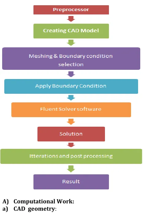
Research algorithm:
A) Computational Work: a) CAD geometry:
[image:5.612.337.565.74.186.2] [image:5.612.50.283.161.509.2]In this analysis, 3-D model of the receiver’s tube has created with the help of design software ANSYS Fluent 16.0.
[image:5.612.338.562.329.419.2]Fig: - Geometry of the circular section tube.
Fig: - Geometry of elliptical section tube.
b) Meshing:
After completing the CAD geometry of the receiver tube, it has imported in ANSYS Fluent for further work. The next step just after designed its geometry is meshing. Meshing is a critical operation in finite element analysis, in this process; the designed geometry is dividing into a large number of small elements, which can see in the figure given below:
Fig (a): - Meshing of circular Section tube.
Fig (b):- Meshing elliptical Section tube.
[image:5.612.57.268.561.672.2] [image:5.612.338.562.572.690.2]Fig (d):- Meshing of Chamber in which elliptical tubes are mounted.
Tube
section Assembly Meshing Method
Nodes Elements Mesh Metric
Circular
Fig:(c) Tetrahedrons 79611 408586 Orthogonal Quality Elliptical
Fig:(d) Tetrahedrons 216815 1032953 Orthogonal Quality
Quality of meshing:
The quality of the mesh is an important factor in the output result after analysis. It defines the accuracy and stability in the calculation. If the total number of elements is higher than after calculation, it gives a better result. Some other factors also affect the mesh quality such as,
The computation processing time required:
Time of calculation will relatively higher for a well-refined mesh.
Convergence rate:
If the quality of the mesh is good then the rate of convergence will be greater i.e. accurate solution can achieve faster.
Orthogonal mesh quality:
Vector formula is used for computing orthogonal quality of the cell. Cells orthogonal quality is determined with the help of face normal vector. The normal vector has taken from the cell centroid to centroid of the adjacent face and cell centroid to centroid of each face.
Image source: SHARC.Net
Where, ⃗1, ⃗2 and ⃗3 represent the normal vectors of faces 1, 2, 3 respectively.
The unique thing in the orthogonal mesh is its variation, which generally varies from zero to one. It will close to zero for the worst cells but on the other hand, it will closer to one for the best cells.
B) Defining Material Properties:
The proper selection of material is very important for any analysis. There are more than hundreds of materials by default available in the library of ANSYS. However, if the required material is not available in its dictionary then you can create own material also as per the required condition. In this present work, I have taken copper material.
Material
Name Pipe density (kg/m3)
Thermal Conductivity (w/mk)
Specific Heat (Cp) (J/kgK)
Copper (cu) 8978 387.6 381
[image:6.612.323.577.450.722.2]DATA COLLECTION
For modeling convenience, there is a need for some approximate data. These data have used as a reference for designing. These data have collected from different sources like previous research papers, internet, and steel /thermal plant log tables etc. There are also some hypothetical data has been taken to achieve a good result.
5. RUN CALCULATION
During run calculation, the number of iterations has taken “1000” with an interval of “1” for obtaining the result that is more precise.
6. RESULT ANALYSIS
Graphical result output of temperature, pressure, stress and deformation analysis of central receiver at different parameters. Here two sections of the receiver’s tube have taken into consideration in different circumstances or parameters.
A) Temperature and pressure variation of a complete receiver
Case (i): When the circular pipe has installed inside the block.
Fig:(i)
Fig:(ii)
Case (ii): Elliptical section tube has installed inside the block.
Fig:(i)
Fig:(ii)
B) Total temperature distribution of the receiver’s tube
Case (ii): Thermal variation in receiver’s tube having an elliptical cross-section.
C) Pressure variation
Fig: Circular section tube
Fig: Elliptical section tube
D) Stress variation
Fig: Circular section tube
Fig: Elliptical section tube
E) Total deformation:
Fig: Elliptical section tube
7. CONCLUSION AND FUTURE WORK
In this present work, simulation has been performed on a designed model, in this analysis copper material is taken into consideration and analyzed up to a very high range of temperature and present a new concept of production of electric power through solar hybrid energy. There are two cross-sections of the tube have been taken into consideration i.e. one is circular and another is elliptical. The designed model shows the variations up to a very high range of temperature (which is about 900°C) and some other extreme conditions. Both sections performed differently in different parameters (in some cases). These are the following conclusions have concluded through the above result.
a) Total temperature distribution:-
The total temperature at the outlet is approximately the same (i.e. 750°C) but the area having red colour denoted large in circular section comparatively to elliptical section.
b) Pressure variation
The maximum variation of pressure is a little bit smaller in the elliptical section comparatively circular section.
c) Stress variation
Stress in the elliptical section is to much high comparatively circular section.
d) Total deformation:
Deformation chances are highest at inlet and lowest at the outlet. Especially at inlet turning position is most critical zone.
Finally, this approach will be helpful in producing electricity with the help of hybrid energy sources i.e. solar and coal. The coal consumption of thermal power plant will decrease and also the power generation will more eco-friendly compared to the traditionally running thermal power plants (i.e. purely coal-based power plants). This
approach may be helpful to fill the gap between conventional energy sources and nonconventional energy sources.
References:
1) SunShot initiative, US Department of Energy,
2015. http://energy.gov/eere/sunshot/sunshot-initiative.
2) STAGE-STE EERA, Scientific and Technological
Alliance for Guaranteeing the European Excellence in Concentrating Solar Thermal Energy, 2013. http://www.stage-ste.eu/.
3) G. Flamant, D. Gauthier, H. Benoit, J.-L. Sans, R. Garcia, B. Boissière, et al., Dense suspension of solid particles as a new heat transfer fluid for concentrated solar thermal plants: on-sun proof of concept, Chem. Eng. Sci. 102 (2013) 567-576, https://doi.org/10.1016/j.ces.2013.08.051.
4) H. Benoit, I.P. Lopez, D. Gauthier, G. Flamant,
Temperature influence on wall-to-particle
suspension heat transfer in a solar tubular receiver, Solar Paces 1734 (2015) 040002, https://doi.org/10.1063/1.4949093.
5) C.K. Ho, S.S. Khalsa, N.P. Siegel, Modeling on-sun tests of a prototype solid particle receiver for concentrating solar power processes and storage, in ASME 2009 3rd International Conference on Energy Sustainability, vol. 2,ASME, 2009, pp.
543e550,
https://doi.org/10.1115/ES2009-90035.
6) H. Benoit, Recepteur Solaire Tubulaire a
Suspension Dense de Particules en Ecoulement Ascendant. Universitè de Perpignan, 2015.
7) M. Puppe, S. Giuliano, M. Krüger, O. Lammel, R. Buck, S. Boje, et al., Hybrid high solar share gas turbine systems with innovative gas turbine
cycles, Energy Procedia (2015),
https://doi.org/10.1016/j.egypro.2015.03.129
8) EC, (2004) European Commission 2004, European
Research in Concentrated Solar Thermal Energy, Directorate-General for Research European Commission, Brussels, Belgium.
9) Lienhard, J.H., (2006) A Heat Transfer Textbook,
thirded.hlogiston Press, Cambridge,
10) PS10, (2008) PS10. Available from:
< http://www.ps10.es >.
11) Buck, R., Barth, C., Eck, M., Steinmann, W., (2006) Dual-Receiver concept for solar towers. Solar Energy 80(10), 1249-1254.
12) Chen, G. Q., et al. "Nonrenewable energy cost and greenhouse gas emissions of a 1.5 MW solar power tower plant in China." Renewable & Sustainable Energy Reviews 15.4(2011):1961-1967.
13) Chunxu Du, Pu Wang, Chongfang Ma, Yuting Wu, Shaoqing Shen, A high precision solar position algorithm, Energy Engineering, Vol.2, 41-48, 2010.
14) Ding Weijie, Zhu Xuemei, Modeling and Simulation of Heliostats Field in Solar Power Tower. 978-1-5090-4657-7/17/$31.00© 2017 IEEE.
15) I. Reda, A. Andreas, Solar Position Algorithm for Solar Radiation Applications, Solar Energy, Vol. 75, No. 5, 577-589, 2004.
16) Nussbaumer, T. (2011). Erneuerbare Energien - Solarenergie. Zürich/Horw: Hochschule Luzern – Technik & Architektur.
17) Kolb, G. J. (2007). Heliostat Cost Reduction Study. Albuquerque, New Mexico, USA: Sandia National Laboratories.
18) Hyun Jin Lee, Sang Nam Lee, Jong Kyu Kim (2016). Performance simulation of the central-receiver solar concentration system based on typical meteorological year data. (DOI 10.1007/s12206-016-1153-y).
19) Annual performance of subcritical Rankine cycle coupled to an innovative particle receiver solar power plant M.A. Reyes-Belmonte, A. Sebastián, J. Spelling, M. Romero*, J. González-Aguilar IMDEA Energy Institute, Avda. Ramón de la Sagra, 3, 28935, Móstoles, Madrid Spain.
20) Pillai, Indu R. and Rangan Banerjee. 2009. “Renewable Energy in India: Status and Potential.” Energy 34(8):970–80.
21) www.cspworld.com.
22) Analysis of Global Solar Radiation in Solar Sector: An Empirical Feasibility Study in India. Volume: 05 Issue: 05 | May-2018 IRJET.
23) Renewable energy technologies: cost analysis series. Volume 1: power sector issue 2/5, Concentrating solar power. IRENA, June; 2012.
24) Singh Rajinesh, Miller A, Rowlands S, Jacobs A. Dynamic characteristics of a direct-heated supercritical carbon-dioxide Brayton cycle in a solar thermal power plant. Energy 2013;50:194– 204.
25) Py Xavier, Azoumah Yao, Olives Regis. Concentrated solar power: current technologies, major innovative issues and applicability to West African countries. Renewable and Sustainable Energy Reviews 2013;18:306–15.