© 2019, IRJET | Impact Factor value: 7.34 | ISO 9001:2008 Certified Journal
| Page 1541
Modification of Root Fillet Profile for Optimum Gear Life
Basavaraj R Gundad
1, Prof. Abhay M Kalje
21
ME Student, Mechanical Engineering Dept., N.B. Navale Sinhgad College of Engineering, Solapur, Solapur
University, Maharashtra, India
2
Associate Professor, Mechanical Engineering Dept., N.B. Navale Sinhgad College of Engineering, Solapur, Solapur
University, Maharashtra, India
---***---Abstract -
In this thesis, static contact and deformationanalysis were performed, while trying to design spur gears to resist failure and pitting of the teeth, as both affect transmission error. Numerical methods can potentially provide more accurate solutions since they normally require much less restrictive assumptions. The model and the solution methods, however, must be chosen carefully to ensure that the results are accurate and that the computational time is reasonable. The finite element method is very often used to analyze the stress state of an elastic body with complicated geometry, such as a gear. In this study optimized root fillet is introduced in spur gear and analyzed. Starter pinion is analyzed in ANSYS for deformation and maximum contact stress which causes pitting. Experimental Analysis is done using photoelastic method on photoelastic apparatus and compares the FEM result with experimental result. For this work parametric modeling is done using CATIA V5 and for analysis ANSYS workbench is used.
Key Words
: Root fillet, gear tooth, spur gear, gear
profile, contact stress, pitting, CATIA V5, ANSYS,
photo elastic method.
1. INTRODUCTION
A gear also called as cogwheel is the most important & critical element of power transmission system. Gear is a rotating cylindrical wheel having teeth cut on it, which meshes with another teethed part to transmit the power, in most cases with teeth on the one gear being of identical shape, and often also with that shape on the other gear in mesh. There are different types of gears like Spur, Helical, Worm and Bevel. As the most common type, spur gears are often used because they are the simplest to design and manufacture, less costly, efficient with 98-99% operating efficiency. They are usually employed to achieve constant drive ratio.
2. LITERATURE REVIEW
Sankpalet al. [1] reported the research on contact stress refers to the localized stresses that develop as two curved surfaces come in contact and deform slightly under the imposed loads. Also due to contact stresses wear takes place at gear tooth. Wear is nothing but progressive removal of metal from the surface. Consequently tooth
thins down and gets weakened. In this contact stresses find out by FEM method and experimental method by using the polariscope. And compare the FEM result with experimental result.
Rahateet al. [2] carried out contact stress analysis of steel gear and composite gear using Hertz equation and by Finite Element Analysis using Ansys 16.0 Workbench. Also experimental stresses are calculated using Photo-Stress Method. In this work, Aluminium Silicon Carbide is used as a gear material. When compared, the results of both theoretical method and FEA show a good degree of agreement with experimental results.
Naik et al. [3] analyzed the bending stresses occur on the gear tooth profile when subjected to loading condition with the help of FEM and Photo-elastic technique. Photo elastic stress analysis is a technique that provides stress distribution over an entire object/structural member of interest it is based on the property of some transparent material to exhibit colorful pattern when viewed with polarized light. These patterns occur as the result of alternation of the polarized light by the internal stresses into two waves travel at different velocities. In this work root radius are taken gear parameters, how stress redistribution are taken place by varying this parameter studied. The stresses are calculated with the help of the FEA this result are compared with the stresses calculated by Photo elastic technique. Parametric modeling is done using Pro-e WF 5.0 and for analysis ANSYS 12.0 workbench is used. For photo elastic validation optical polariscope is used .This work helpful to conclude effect of bending stress on gear tooth profile by variation of gear root radius it also give the comparison of FEM method with photo-elastic technique of stress analysis .
© 2019, IRJET | Impact Factor value: 7.34 | ISO 9001:2008 Certified Journal
| Page 1542
less than of a NCR gear for the pair of same module andfixed center distance. Hence the load carrying capacity of the HCR gear is 18% more than the NCR gear designed for the same weight, fixed module and same centre distance of gear pair.
Patil et al. [5] reported the contact stresses among the Spur gear pair and Helical gear pair, under static condition by using 3D finite element model. The Helical gear pair on which the analysis was carried out were 0°, 5°, 15°, 25° helical gear set. During analysis FE gear model was verified with Hertz/AGMA equation for zero coefficient of friction. The FE model of gear pair are compatible in evaluating the contact stresses and the results obtained are in good agreement with analytical calculations. For the spur gear pair the increase in contact stress with the increase in coefficient of friction was about 10%.
Karaveer et al. [6] investigated the stress analysis of mating teeth of spur gears to find maximum contact stress in the gear teeth. The results obtained from Finite Element Method are compared with theoretical Hertzian equation values. The spur gears are sketched, modeled and assembled in ANSYS 14.5 Design Moduler. The results show that the difference between maximum contact stresses obtained from Hertz equation and Finite Element Analysis is very less and it is acceptable also the deformation patterns of steel and cast iron gears depict that the difference in their deformation is negligible. Shinde et al. [7] mentioned a pair of spur gear teeth in action is generally subjected to two types of cyclic stresses as bending stresses inducing bending fatigue and contact stress causing contact fatigue. Both this type of stresses may not attend their maximum values at same point of contact fatigue. These types of failures can be minimized by careful analysis of the problem during the design stage and creating proper teeth surface profile, in order to analyze spur gear pair a 3D deformable-body (model) of spur gear is developed and bending stress analysis will be performed as it affects transmission.
Sankaret al. [8] examined teeth failure of spur gear. The spur gear with less than 17 numbers of teeth had the problem of undercutting during gear manufacturing process which minimizes the strength of gear at root. Circular root fillet instead of the standard trochoidal root fillet is introduced in spur gear and analyzed using ANSYS. From the study it is found that the circular root filled design is particularly suitable for lesser number of teeth in pinion andwhere as the trochoidal root filled design is suitable for higher number of teeth.
Rameshkumaret al. [9] considered actual shape of trochoid whereas the fillet radius is assumed as a constant radius curve for calculating the geometry factor presented by AGMA. The FEA of final drive gear assembly of Military vehicle for both NCR and HCR is examined and found the
contact stresses are more than 25% less in HCR gears compared to NCR gears. The load carrying capacity of HCR gearing could be increased by at least 25% for the same weight and volume.
Mao [10] concentrates on the gear fatigue wear reduction through micro-geometry modification method. An advanced non-linear finite element method has been successfully used to accurately simulate gear contact behavior. The models have used true three dimensional gear teeth profiles with micro-geometry modifications under real load conditions. The shaft misalignment, deflection and assembly deflection effects on gear surface contact behavior have been investigated. The optimized micro-geometry based on the analysis has been proposed to reduce surface contact fatigue failure. The model has been very successfully applied in automotive transmission gear surface fatigue wear reduction. The highly accurate gear micro-geometry modification method has improved the gear surface fatigue wear significantly. This method can also be applied to transmission system noise analysis in term of transmission error reduction.
3. OBJECTIVES
The main objective behind this work is to check the behavior of unusual contact between flywheel ring gear and starter motor pinion. Following are major objectives of present work.
1. To find out the stress generated at the root of pinion 2. To predict stress and deformation generated on pinion in order expose the behavior of pinion when comes in contact with ring gear.
3. The tooth profile is modified at root and modified system is analyzed for predicting effect of tooth modification on stresses generated, deformation of tooth.
4. The photo elastic experimentation analysis is also completed in transmission type polariscope along with the finite elemental analysis in Ansys.
4. METHODOLOGY
4.1 Properties of material:
Compressive Yield Strength 250MPa Tensile Yield Strength 250MPa Tensile Ultimate Strength 460MPa
Young's Modulus 200GPa
Poisson's Ratio 0.3
Density 7850 kg m3
© 2019, IRJET | Impact Factor value: 7.34 | ISO 9001:2008 Certified Journal
| Page 1543
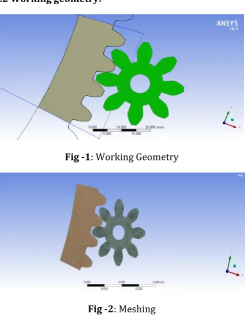
4.2 Working geometry:Fig -1: Working Geometry
Fig -2: Meshing
Fine meshing is applied to pinion for obtaining more precise results i.e. contours after meshing number of nodes and elements are 11221 and 10744 respectively, meshing of the geometry shown in Fig-2.
4.3 Finite Element Analysis of System
4.3.1 Pre-processing and Boundary Condition
The model is imported to ANSYS Design Modular for CATIA V5R18, this model consists of 126 teeth Ring gear and 8 teeth pinion. For the ease of working and reducing analysis time the number of tooth on ring gear are reduced to 4 tooth only, this action is done by using “slice” command available in ANSYS design modular. After applying Slice to ring gear geometry shown below
4.3.2 Load and Boundary Condition of Connecting
Rod
In case of FEA the pinion is added as a contact body and ring gear as a target body shown in Fig-3. The type of contact used is frictionless no separation type, shown in Fig-4. The no separation contact is added between two tooth in contact.
Fig -3: Contact between gear teeth
Fig -4: Type of support
The revolution of pinion is considered for “RZ” direction while ring gear is kept at constant position shown in Fig-5. The ring gear body is considered as a fix support, moment of “27852 N-mm” is added along Z-Axis i.e. it will rotate along Z direction. The specification of particular starter motor is 1200RPM and the rated power output is 3.5KW. The moment applied is shown in Fig-6
[image:3.595.42.284.101.411.2][image:3.595.331.537.568.695.2]
© 2019, IRJET | Impact Factor value: 7.34 | ISO 9001:2008 Certified Journal
| Page 1544
Fig -6: Moment applied to pinion
5. RESULTS
5.1 FEA Results
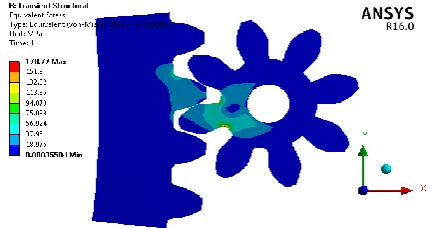
For the predictions of maximum deformation and equivalent stress generated, the system of gears is analyzed by modifying it with different cases of varying fillet radius. The modification range is from 0.5mm to 1.5 mm at an interval of 0.25 mm, results of analysis parameters is compared with the results obtain from working geometry.
Fig -7: Deformation in working geometry
[image:4.595.324.547.287.401.2]Fig -8: Stresses in working geometry
5.1 Deformation and Stresses in modified
geometry of 0.5 mm root fillet.
[image:4.595.49.551.385.778.2]Fig -9: Deformation in modified geometry of 0.5 mm root fillet
Fig -10: Stresses in modified geometry of 0.5 mm root fillet
5.2 Deformation and Stresses in modified
geometry of 0.75 mm root fillet
Fig -11: Deformation in modified geometry of 0.75 mm
root fillet
[image:4.595.56.271.405.534.2]© 2019, IRJET | Impact Factor value: 7.34 | ISO 9001:2008 Certified Journal
| Page 1545
5.3 Deformation and Stresses in modified
geometry of 1.0 mm root fillet
[image:5.595.43.563.49.434.2]Fig -13: Deformation in modified geometry of 1.0 mm root [image:5.595.53.276.285.399.2]
fillet
Fig -14: Stresses in modified geometry of 1.0 mm root fillet
5.4 Deformation and Stresses in modified
geometry of 1.25 mm root fillet
[image:5.595.320.546.287.410.2]Fig -15: Deformation in modified geometry of 1.25 mm
root fillet
Fig -16: Stresses in modified geometry of 1.25 mm root fillet
5.5 Deformation and Stresses in modified
geometry of 1.5 mm root fillet
Fig -17: Deformation in modified geometry of 1.5 mm root [image:5.595.45.280.459.568.2]
fillet
Fig -18: Stresses in modified geometry of 1.5 mm root fillet
5.2 EXPERIMENTAL ANALYSIS
5.2.1 Two-dimensional Photoelasticity
The foregoing is a rather general description of the formation of photoelastic patterns. It applies equally well to two-dimensional and three-dimensional photoelasticity and to the method of photoelastic coatings. Now, let us restrict the discussion to plane-stress systems, so that the basis of photoelasticity can be developed without needless complications. A plane-stress problem is approached when the thickness (lateral dimension) of the prototype and the model is small in relation to dimensions in the plane, and the applied forces act in the plane at mid thickness. For such a system, we are concerned with stresses acting parallel to the plane of the model only, for all other stress components are zero.
[image:5.595.46.283.597.739.2]© 2019, IRJET | Impact Factor value: 7.34 | ISO 9001:2008 Certified Journal
| Page 1546
For two dimensional analysis, the most sufficientdimensionless ratio is the ratio (
) Where is the stress at any point, ‘P’ is the applied load, h is the thickness and ‘l’ is the typical length dimension. If subscripts ‘p’ and ‘ m’ refer to the prototype and model respectively. Scale relation as follows,
The values of stresses and loads in prototype i.e.
and ‘Pp’ are taken from theoretical analysis of gear. The value of model thickness 20 mm and prototype thickness 8 mm are used for polariscope calculations.
5.2.2 Technical Data (Light source)
a) lamp box with white diffuser b) For white light:-
1 fluorescent tube
2 incandescent lamps, candle bulb, matt inner E14, 235V, 25W
c) For monochromatic light (color yellow) 1 sodium vapor lamp SOX 35, 35W
d) Filter, enclosed in glass, diameter: d=425mm e) - 2 polarization filters (dark olive)
f) - 2 quarter wave filters (colorless) g) Frame W×H : 600×750mm
5.2.3 Specifications of polariscope
For experimentation the “Transmission Polariscope” is used.
1. Representation of mechanical distribution of stress in photo elastic experiments.
2. 2 plane polarisation filters as polarizer and analyser.
3. 2 quarter wave filters to generate circular polarized light.
4. All filters with 360° angle scale and marking of the main optical axis.
5. White light generated using a fluorescent tube and two incandescent lamps.
6. Monochromatic light (colour yellow) generated using a sodium vapour lamp.
7. Filters roller bearing mounted and rotating. 8. Frame cross-arms height-adjustable.
[image:6.595.318.553.53.248.2]9. Generation of compression or tension forces by means of a threaded spindle.
Fig -19: Experimental Setup
5.2.4 Stress optic law
Certain transparent material are isotropic when unstressed become doubly refracting when subjected to stress or strain birefringence is called photo elastic effect. Maxwell found that orthogonal axis of polarization coincides with the directions of principle stresses and change in index of refraction along each axis is linearly proportional to stress developed. Accordingly to Maxwell theory,
(n
1-n
2) = K (
1-
2) ………. (a)
Where,
n
1and n
2 are indices of refraction along directions of principle stress 1and
2 and K is constant called as Stress optic coefficient.The polarized light vector splits into two components along axis of 1
and
2p
ropagates with different velocities say V1 and V2 required for light vector to come out of thickness h will be,t
1= h / V
1and t
2= h / V
2Relative retardation in time will be
(t
1- t
2) = h(1/ V1 – 1/ V2 )
If C is velocity of light in air, in the relative distance between two components will be,
( ) (
V1 – C/ V2)
But,
V1 = n
1and
V2 = n
2( )
© 2019, IRJET | Impact Factor value: 7.34 | ISO 9001:2008 Certified Journal
| Page 1547
For linear retardation of one wavelength λ, the angularretardation is
2λ
radians, hence the angular retardation for linear retardation will be,
/ λ
/ λ
2
(
1-
2)
1
-
2 =1
-
2 =Where,
N =
f
=
Material fringe value h = model thickness in mmThe above equation gives practical expression of stress optic law which is used for determining the stress difference
( 1
-
2). Material fringe value can be find out bycalibration of photoelastic material, model thickness is known and fringe order is find out by experimentally using polariscope.
[image:7.595.320.548.263.400.2][image:7.595.324.546.434.585.2]
Fig -20: Gear after machining
Fig -21: Obtaining value of
”
material Fringe valueFig -22: Loading of assembly on polariscope
Fig -23: Photoelastic gear at no load condition
Fig -24: Fringe pattern
[image:7.595.58.264.447.580.2] [image:7.595.56.268.609.743.2]
© 2019, IRJET | Impact Factor value: 7.34 | ISO 9001:2008 Certified Journal
| Page 1548
Experimentation Results
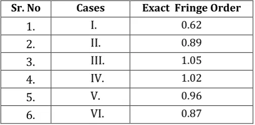
In this determining the stress values from the observed fringe order. The fringe order observed from the experimentation is as shown in Table -1.
Sr. No
Cases
Exact Fringe Order
1.
I.
0.62
2.
II.
0.89
3.
III.
1.05
4.
IV.
1.02
5.
V.
0.96
[image:8.595.36.288.161.285.2]6.
VI.
0.87
Table -1: Exact Fringe Order for six cases
5.2.5 Determining material fringe value
As we know;
f
=8p /
where,
N = Exact fringe order
P = Load applied
D = Diameter of Disc
Putting Values in equation above
f
= 8×101.936
/
f
= 7.186
The material fringe value (
f
) is important for calculating stress and it common for all calculations.5.2.6 Determining stress values for working
geometry
I. Determining stress values for geometry with
root fillet of 0.25mm
By stress optics law,
1
-
2 =1
-
2 =Put
2=0
1
=
p
= 0.5569 N/mm
2P= Prototype
M= Model
After rearrange the equation above, we get;
II. Determining stress values for geometry with
root fillet of 0.5mm
By stress optics law,
1
-
2 =1
-
2 =Put
2=0
1
=
p
= 0.801 N/mm
2P= Prototype
M= Model
III. Determining value of
for geometry with
root fillet of 0.75mm
By stress optics law,
1
-
2 =1
-
2 =Put
2=0
© 2019, IRJET | Impact Factor value: 7.34 | ISO 9001:2008 Certified Journal
| Page 1549
P= Prototype
M= Model
IV. Determining stress values for geometry with
root fillet of 1.0mm
By stress optics law,
1
-
2 =1
-
2 =Put
2=0
1
=
p
= 0.916 N/mm
2P= Prototype
M= Model
V. Determining stress values for geometry with
root fillet of 1.25mm
By stress optics law,
1
-
2 =1
-
2 =Put
2=0
1
=
m
= 0.87 N/mm
2P= Prototype
M= Model
VI. Determining stress values for geometry with
root fillet of 1.50mm
By stress optics law,
1
-
2 =1
-
2 =Put
2=0
1
=
p
= 0.75 N/mm
2P= Prototype
M= Model
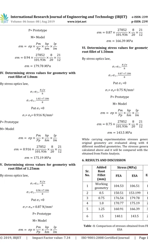
While carrying experimentation stresses generated in original geometry are evaluated along with the five different modified geometries. The stresses generated are calculated above and it will be compared with the results obtained from Finite Analysis.
6. RESULTS AND DISCUSSION
Sr.
No.
Added
Root
Fillet
(mm)
Stress (MPa)
%
Error
FEA
ESA
1
geometry
Working
104.53
106.51
1.86
2
0.5
150.51
153.199
1.76
3
0.75
176.54
179.78
1.80
4
1.0
170.77
175.19
2.25
5
1.25
160.91
166.39
3.29
[image:9.595.36.528.0.814.2]6
1.5
140.1
143.5
2.37
© 2019, IRJET | Impact Factor value: 7.34 | ISO 9001:2008 Certified Journal
| Page 1550
7. CONCLUSIONS
From the present work investigation and optimization of root fillet of starter pinion gear conclusions drawn are 1. The stresses generated are within the maximum permissible limit of material i.e.
250MPa.The deformation is reduced from 0.0102 mm to 0.0093239mm.The best root fillet radius observed is 1.5mm in which equivalent stress generated 140.1MPa and deformation 0.00792mm.
2. FEA is a good tool for analyzing contact problems in which mathematical formulation of the system consists is quite difficult and need to have number of assumptions. 3. The results of stresses obtained from photoelastic analysis are in good agreement with the results obtained from finite technique.
4. Finite Element method is very effective in order to predict stresses & deformations in system. Both the analysis techniques used in this study are non- destructive type, hence these techniques are very cost effective also. 5. The error observe while comparing results can be because of involvement of human being. The observation capacity & excellent operating skill is required by an operator while using polariscope, even a small variation in observation can lead to high Fluctuation in final results.
FUTURE SCOPE
While working on this system it is observed that, there are lot of things that can be done over, the area of contact analysis quite interesting because of availability of effective analysis tools, some of the recommendations for further work are discussed below for specific case of Starter motor pinion and flywheel ring gear.
Tip relief can be added to pinion as well as to ring gear and analyzed for its effect, also effect of involutes tooth profile and circular root fillet, cycloidal tooth profile with circular root fillet can be studied.
This system can be studied or analyzed using different solvers available in order to see which solver can be effective, can solve equations in less possible time, easy to form and work with system.
Effect of burr trapped between teeth contact can be one of the interesting topic, because in case of pitting failure small pits are observed on teeth face, while in dry or non-lubricated meshing condition that small burr particle can damage teeth.
Different type of available materials can be assigned to the system and probability of material combination can be
studied, also fatigue life cycle of the system can be analyzed at rated number of operating cycles.
REFERENCES
[1] Sankpal A. M and M. M. Mirza, “Contact stress analysis of spur gear by photoelastic technique and finite element analysis”, International journal on theoretical and applied research in mechanical engineering (IJTARME), (2014) ISSN: 2319-3182, Volume -3, Issue-2,
[2] Rahate H. P and Marne R. A. “Contact stress analysis of
composite spur gear using photo-stress method and finite element analysis” (IRJET) (2016) ISSN: 2395 -0056 Volume: 03 Issue: 07
[3] Naik K. N. and Dhananjay R. D. “Static analysis of
bending stresses on spur gear tooth profile by using finite element analysis and photo elastic technique “International journal of current engineering and technology (IJCET) (2016) ISSN: 2277 – 4106
[4] M. Rameshkumar, G. V and P. Shivkumar, “Finite
element analysis of high contact ratio gear” AGMA Technical paper, (2010)ISBN: 978-1-55589-981-3
[5] Patil S S., Saravanan K, Ivana A and Azmi A W, “Contact
stress analysis of helical gear pair including frictional coefficient”, International journal of mechanical sciences.85 (2014)ISSN: 205–211
[6] Karaveer V, Ashish M and T. Preman R. J, “Modeling
and finite element analysis of spur gear”, International journal of current engineering and technology, (IJCET) (2013) ISSN: 2277-4106
[7] Shinde S.P. ,Nikam A.A., Mulla T.S., “Static analysis of
spur gear using finite element analysis”, IOSR journal of Mechanical and Civil Engineering, ISSN: 2278-1684
[8] Sankar S., Sundar Raj M., Nataraj M., “Profile
Modification for Increasing the Tooth Strength in Spur Gear Using CAD”, Scientific Research Journal, (2010) ISSN:1947-3931.
[9] Rameshkumar M., Shivkumar P., Sundareshand S.
Gopiath K., “Load sharing analysis of high contact ratio spur gears in military tracked vehicle applications”, gear technology, July 2010.
[10]K. Mao, “Gear teeth contact analysis and its application
in the reduction of fatigue wear”, Wear 262 (2007), ISSN 1281–1288
[11]Dr. Ir H.G. H. van Melick, “Tooth-Bending Effects in
© 2019, IRJET | Impact Factor value: 7.34 | ISO 9001:2008 Certified Journal
| Page 1551
[12]Fatigue Data at zero mean stress comes from 1998
ASME BPV Code, Section 8, Div 2, Table 5-110.1
[13]R.S. KHURMI and J.K. GUPTA, Machine Design, Ist
Edition, Eurasia Publishing House (Pvt.) Ltd, Ram Nagar, New Delhi-110 055 (2005), 1043-1044.
[14]J. Shigley, Mechanical Engineering Design, Eighth
Edition, McGraw−Hill, USA, 2006.
[15]Gear Reference Guide, Berg Manufacturing,


