Embedded Software of Automatic Sector Switching
Antenna System for UAV Data Link and SOTM
Ravi Kant
Defence Electronics Applications
Laboratory (DRDO), Dehradun,
Uttarakhand, India.
Pramod Kumar Verma
Defence Electronics Applications
Laboratory (DRDO), Dehradun,
Uttarakhand, India.
Vinod Kumar Singh
Defence Electronics Applications
Laboratory (DRDO), Dehradun,
Uttarakhand, India.
ABSTRACT
During the last decade the development of Unmanned Aerial Vehicles (UAVs) has increased drastically. Together with the development of technology, Unmanned Air Vehicle System (UAVS)’s usage is growing day by day, so it is very important that UAV’s data link system has to be firm and reliable. Since the data link is the lifeline of UAV being remotely controlled by ground pilot it must be accurate & precise and continuous. Now a day’s UAVS/ Drone are produced by many suppliers but most important thing is to provide reliable and secure data links. To provide the continuous data link between ground system and UAV, Omni and Directional antenna are being used based on the range and coverage requirements. Conventional Airborne Antenna Tracking Systems consisting directional antenna are bulky as they consist mechanical rotating part i.e. Positioner, which needs high degree of stability, of the airborne platform. Proposed software driven Automatic Sector Switching Antenna System (ASSAS) for UAV and for Satcom-On-The-Move (SOTM) applications offers many advantages in terms of weight, volume, size and cost. The key challenge of ASSAS is the development of reliable and ruggedizes software, which has been described in details in this paper.
General Terms
Embedded Software, Automatic Sector Switching Antenna System, Look angle calculation algorithm, C-band and S-band antenna, Antenna Control Unit (ACU).
Keywords
UAVs, Sector Switching Antenna, Data Link, ACU, RTOS, Embedded Software, ARM cortex M4,freeRTOS.
1.
INTRODUCTION
Datalinks for UAV’s primarily consists of Up-link Commands shall be communicated continuously to the UAV during Take-Off, Landing and cruise phases and Down-link for presentation of information from UAV to the payload operator, the air-vehicle data and payload data to the GCS (Ground Control Station). To provide the continuous datalink between UAV and GCS, on-board Omni antenna as well as Directional antenna with tracking system is used. Since the usage of on-board Omni antenna provides limited range due low gain and high perturbation effects, therefore on-board directional antenna with tracking system is required to enhance the datalink range. But due to the mechanical movement of airborne data terminal, its stability on airborne platform is one of the main issues [1]. In this paper we are presenting an innovative approach of software controlled Automatic Sector Switching Antenna System. It eliminates completely moving part such as slip ring, motor, pedestal from conventional systems and provide continuous data link between Ground Station and Airborne Platform.
2.
SYSTEM REQUIREMENT
Two types of Automatic Sector Switching Antenna systems are realized in S & C band frequencies. S-Band Sector Switching antenna system is based on twelve sector antennas to provide continuous link with geostationary satellite while mounted on the moving ground platform for Satcom on The Move operation. C-band Sector Switching antenna system is based on eight sector antennas to be mounted on airborne platform to provide continuous link between airborne and ground control station. Antenna System assemblies will mainly consists of
1) Multi Sector Antenna System including Radome
2) Multi-Channel Antenna Controller
3) Software for Multi-Channel Antenna Controller.
2.1
C-Band Sector Switching Antenna
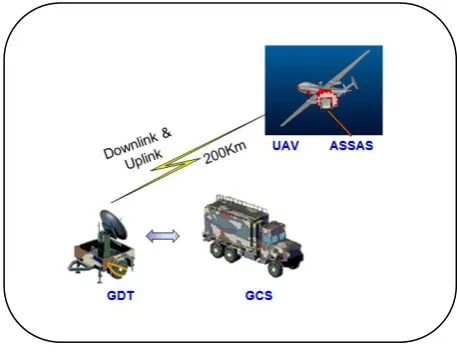
[image:1.595.314.543.537.715.2]C-Band Sector switching antenna mounted on the UAV platform with 15% bandwidth is required to provide continuous link Ground Control Station. Antenna design is based on the innovative concept of Beam switching antenna which consist of 8 planar antennas, 7 on sides and one on top to provide the hemispherical coverage. Microstrip Patch antenna technology in comparison of conventional antennas such as horn etc. offers many advantages in terms of weight, size, volume, cost and performance. Due to high efficiency and compact in size Microstrip antennas are widely used for data link applications [2]. Operational scenario of C-Band datalink between airborne and Ground systems is shown in figure-1.
Fig 01: Operational Scenario for UAV Data Link
2.2
S-Band Sector Switching Antenna
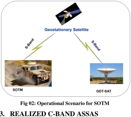
6 towards geostationary satellite as SOTM operation. Antenna
[image:2.595.316.542.72.271.2]design is based on the Beam switching antenna which consists of 12 planar antennas, 11 on side and 1 on top side to provide the hemispherical coverage. It offers many advantages in terms of weight, size, volume, cost and performance. Operational scenario of S-Band SOTM systems is shown below in figure-2.
Fig 02: Operational Scenario for SOTM
3.
REALIZED C-BAND ASSAS
HARDWARE
[image:2.595.55.281.149.351.2]C-band planar antennas have been designed based on Microstrip patch configuration to get the advantage of low profile, low volume and low weight. To achieve the wide bandwidth special techniques using electromagnetic coupling between stacked patch has been used. Prototypes of these antennas have been developed and various design parameters have been validated by means of radiation patterns and return loss measurements. Photographs of realized C-Band ASSAS Antenna hardware are shown in figure-3. Various other components of ASSAS such as: GPS antenna with integrated receiver Attitude and Heading Reference System (AHRS) sensor, SP8T RF Switch and Antenna Controller Unit are shown in figure-4.
[image:2.595.316.545.459.607.2]Fig 03: Automatic Sector Switching Antenna System (ASSAS)
Fig 04: ASSAS Hardware Components
4.
ANTENNA CONTROL UNIT (ACU)
Antenna Control Unit (ACU) is the brain of the antenna control system used for controlling the antenna in open loop tracking and closed loop tracking [3]. The antenna look angle is calculated by using look angle algorithms mentioned in subsequent paragraph 5.1 Then calculated look angle i.e. Azimuth (AZ) and Elevation (EL) angle will be checked against the sectoral antenna coverage range as per the pre-defined look-up table. Accordingly ACU software will select desired sector antenna based on the calculated look angle and pre-defined sector antenna coverage range. The update rate of the interface module i.e. getting sensor data in every 100ms, during this period ACU Software receive data from AHRS and GPS [4].
Fig 05: ASSAS Interface Diagram
[image:2.595.60.275.507.669.2]4.1
Open Loop Tracking
This method combines data from GPS and AHRS mounted on the vehicle to calculate its position (Lat, Long) and orientation with respect to global axes. Relative beam pointing elevation and azimuth angles are calculated using position values of vehicle w.r.t. geostationary satellite. Accordingly sectoral Antenna selected using a multi port RF switch. This operation is repeated based on sensor data update rate to maintain the continuous communication link.
Components Required for Open Loop Tracking: a) GPS Unit
b) AHRS
c) Microcontroller
4.2
Closed Loop Tracking
In this method, RF signal from received RF chain is coupled using a coupler and measured for its power level using a RF detector. This value is digitized and stored in a look up table. Process is repeated for all the sectors in a sequential manner, and sector with maximum value is selected for establishing the link. Once the initial operation is completed, this is repeated only if measured value of incoming RF signal goes below a pre defined threshold.
Components Required for Closed Loop Tracking: a) RF Coupler,
b) Band Pass Filter, c) LNA,
d) RF Detector, e) ADC,
f) Microcontroller
Open loop tracking will be the primary method for antenna selection whereas closed loop tracking can be used for automatic selection in the absence of GPS and AHRS data.
5.
ACU SOFTWARE REQUIREMENT
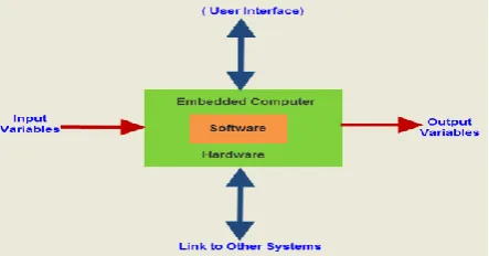
[image:3.595.57.279.613.729.2]ACU is an Embedded System which is based on Embedded Software. Embedded Software is use to control the functions of various hardware devices and systems. Embedded Software controls device functions in the same way that a computer’s operating system controls the function of software applications. Almost any device can contain embedded software – from those so simple you might not imagine they had computer control, like toasters and light bulbs, to complex tracking systems in missiles and satellite. A general diagram of any Embedded System is given in Fig: 06
Fig 06: Basic Diagram of Embedded System
The main requirement of the ACU software is to calculate the Azimuth (AZ) and Elevation angle (EL) with respect to Ground Data Terminal (GDT) or Geostationary satellite and selection of sectoral antenna. The AZ and EL position of the antenna is required to be stabilized in space as the aircraft rolls, pitches and yaws. Stabilization is achieved by transforming the Earth's North East Down (NED) frame antenna angles to the body frame using the instantaneous body aircraft attitudes supplied by AHRS.
5.1
ACU Software Algorithm for
Calcula-tion of Antenna look angle
It is necessary to choose a reference coordinate system in which the states of both the satellite and aircraft position can be represented. For the purposes of measuring and determining the aircraft and satellite positions it is convenient to use Earth-Centered, Earth-Fixed Frame (ECEF) frame coordinate system [6]. The ECEF has two common coordinate systems: a polar-type "latitude-longitude-height" called geodetic coordinates, and the simpler three Cartesian axes X,Y, Z . Global positions are often given in lat-long-height coordinates (geodic coordinates), but since X,Y, Z are far easier to work with, we'll convert all lat-long-height to X,Y,Z. Hence satellite and aircraft positions are converted from geodic coordinates to Cartesian coordinates. After that the equation of line joining aircraft and satellite in ECEF Frame of reference is determined and then it is important to do coordinate transformation from ECEF frame to the navigation frame (NED Frame). NED frame, antenna angles are then converted to the body frame using the instantaneous body aircraft attitudes to determine the AZ, EL position of the antenna.
Geodic (Latitude, Longitude and Height) to ECEF( X ,Y ,Z ) Transformation :
X= (N+h) cosα cosɷ Y= (N+h) cosα sinɷ Z= [N(1-e^2)+h]sinα
α,ɷ,h = geodic latitude, longitude and height ,
X,Y, Z = earth centered earth fixed Cartesian coordinates a = semi major earth axis(ellipsoid equatorial radius) b = semi minor earth axis(ellipsoid polar radius)
N = radius of curvature in prime vertical
Flattening
F = (a-b) / a;
Eccentricity squared
e = eccentricity square of flattening F
ECEF( X,Y ,Z ) to Geodic (Latitude, Longitude and Height ) Transformation
p = Square root of (X +Y )
ECEF vector to NED Transformation
8
𝐶(𝛼, 𝜔) =
−𝑆𝑖𝑛𝛼 𝐶𝑜𝑠𝜔 −𝑆𝑖𝑛𝛼 𝑆𝑖𝑛𝜔 𝐶𝑜𝑠𝛼
−𝑆𝑖𝑛𝜔 𝐶𝑜𝑠𝜔 0
−𝐶𝑜𝑠𝛼 𝐶𝑜𝑠𝜔 − 𝐶𝑜𝑠𝛼 𝑆𝑖𝑛𝜔 −𝑆𝑖𝑛𝛼
Vector in NED Frame(rn) :
𝑟𝑛 = 𝑥 𝑦 𝑧𝑁𝐸𝐷
= 𝐶 𝛼, 𝜔 𝑥 𝑦 𝑧 𝐸𝐶𝐸𝐹
NED to Body frame Transformation
The instantaneous attitude of the aircraft body w.r.t. to NED frame are the three Euler angles viz, ψ yaw, θ pitch and ϕ roll. In order to position the antenna in the required direction in space, one more transformation is required from NED frame to the Body frame. yaw, pitch and roll rotation matrices, Cl, C2 and C3 respectively where
𝐶1 =
𝐶𝑜𝑠ψ 𝑆𝑖𝑛ψ 0
−𝑆𝑖𝑛ψ 𝐶𝑜𝑠ψ 0
0 0 1
𝐶2 =
𝐶𝑜𝑠θ 0 −𝑆𝑖𝑛θ
0 1 0
𝑆𝑖𝑛θ 0 𝐶𝑜𝑠θ
𝐶3 =
1 0 0
0 𝐶𝑜𝑠 ϕ 𝑆𝑖𝑛 ϕ
0 −𝑆𝑖𝑛 ϕ 𝐶𝑜𝑠 ϕ
𝑟𝑏 = 𝐶 𝑛𝑏. 𝑟𝑛
where 𝐶𝑛𝑏 = 𝐶3 ∗ 𝐶2 ∗ 𝐶1 transforms vector rn in the navigation frame to vector rb in the body frame.
Body frame to Az, EL angle transformation
Once the direction cosines of the vector in the body frame are obtained, it is a simple matter to calculate Azimuth (AZ) and Elevation (EL) angles of this vector.
Once ACU calculates these two parameters (AZ and EL angle), these parameters are matched with pre-defined angle versus sectoral antenna as per look-up Table and then ACU switch-on those corresponding sector antenna. Same algorithms have been used in S-band & C-band ASSA System, both systems was tested on 3-Axis Test Bench facility, which can move ASSA system in all the three axis (roll, pitch and yaw) simultaneously and result were captured using data logging device and after analysis it was found to be satisfactory.
6.
VERIFICATION AND VALIDATION
RESULTS
[image:4.595.323.538.171.374.2]Automatic Sector Switching Antenna (ASSA) System was installed on the 3-Axis Test Bench Facility.
Fig 07: Block Diagram of ASSAS with 3-Axis Test Bench
Detailed testing of the system was carried to verify the functional requirements by means of rotating the system in all the 3-axis using 3-axis test bench setup in Roll, Pitch and Yaw
axis motions. Antenna switching was verified with GUI Software and RF Power received at ASSA System using Handheld Spectrum Analyzer. Block diagram of test set-up is shown in Fig 07.
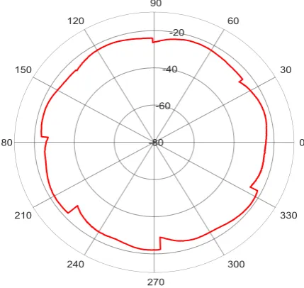
ASSA System testing was carried-out at open antenna test range by placing ASSA system at 2-axis Positioner at receiver side and standard horn antenna was used at transmit side. ASSA system was rotated in Az direction with 90 deg/minute.
Fig 08: AZ Antenna Radiation Pattern of ASSAS
Received power level was plotted with respect to Azimuth angle in polar format to get Az pattern of ASSA system as shown in Fig 08.
7.
CONCLUSION
Proposed Automatic Sector Switching Antenna System (ASSAS) supports the continuous data link between UAV and Ground Data terminal and SOTM link between ground vehicle and geostationary satellite. Proposed antenna control algorithm reduces the stability and complex control system issues associated with mechanical moving parts in case of conventional tracking systems. Present system offers many advantages in terms of weight, size, volume, cost, performance and ruggedness in comparison of conventional tracking systems. It is completely Embedded Software driven system that makes Sector Antenna System as a Smart Antenna System.
8.
ACKNOWLEDGMENT
The authors express their sincere gratitude and thank to Director - DEAL and Group Director (Telematics) for being a constant source of guidance, continuous support, encouragement and granting the permission to publish this paper.
9.
REFERENCES
[1] A. Mevlutoglu, “Unmanned aerial vehicles and network based communication concept,” in Proc. Mechanical Engineers VII. National Aircraft and Aerospace Engineering Conference, Eskisehir, May 22-23, 2009.
[image:4.595.53.279.616.717.2][3] Katsuhiko Ogata , Modern Control Engineering , Fifth Edition, Prentice Hall, Boston Columbus, New Yark. [4] Raj Kamal, Embedded System Architecture,
Programming & Design, 3rd Edition, Tata Mcgraw-Hill education, 2011.
[5] Byeongdo Kang, Young-Jik Kwon, Roger Y. Lee, "A
Design and Test Technique for Embedded Software", Proceedings of the 2005 Third ACIS Int'l Conference on Software Engineering Research, Management and Applications (SERA’05) 0-7695-2297-1/05, 2005