Design a Prototype of a Smart Meter based IOT using
GSM Technology
Ali F. Marhon
College of Electric Engineering
Basrah University
Ikraam Kassim Abid
Collage of Computer Science
Basrah University
ABSTRACT
The internet of things (IOT) is a term refer to the networking between computers , devices , sensors , and objects with each other using a communication technologies to simplify the human life in less human entry. The smart meter is one of the IOT applications , where the smart meter is a device are used to record the reading of the consumed electricity and sent it to the electricity provider remotely to solve the problems which resulted from the tradition way to read the meters. The aim of this paper is to present a design of a smart meter using a wireless technology. The idea of the presented design is to help the consumer to pay the electricity cost to the electricity provider by prepaid way. And to help the consumer to control and monitor the home appliances remotely by their phones. The presented meter also switch off the home appliances sequentially when the meter balance close to runout . GSM technology is used as a communication technology to transform the data between the meters, consumers , and the electric service provider .
General Terms
Internet of Things, IOT , Smart meter , wireless technology , Arduino Mega
Keywords
Arduino , Smart Meters , GSM technology , IOT , wireless technology
1.
INTRODUCTION
The traditional way which is used to read the meters in Iraq is not practical , because it suffered from many problems and difficulties from electric service provider side and from the consumer side ; The common problems from the electricity service provider side are :the efforts and the number of the employees which required to collect the bills from the many consumer's meters against the high number of the consumers , the long time to complete this operation , add to that, this operation is error prone because it is done manually by the human ; And from the consumer side : the traditional meter may record a high value of electricity consumption , while the consumer is exaggerate in electricity consumption without an idea about the cost of the energy value of the power because he consumed the energy without knowing the differences in the rationalization cost , when he reduced his electricity consumption . The proposed smart meter is designed to solve many of these problems . The consumer can pay the electricity bill cost by prepaid , where the consumer can recharge his meter by sending the card code of the electricity balance to the electricity provider remotely using the mobile SIM card to send the card code as SMS via GSM technology.
2.
RELATED WORKS
Many studies are presented in this field , some of them are:
In 2013 R. R.Hariharan et al. published a developed system can be useful for power controlling and management, it shares power for every consumer depending upon the priority setting, even when there is power shortage, all the houses connected to a network or grid will be supplied with power to run the minimum essential loads, while the less priority loads will be switched off automatically[1].
In 2014 Atheena Charly et al. designed a hardware model to provide an efficient management of electrical energy in homes, which checks electricity consumption and controls the electric energy used with the demand response technique using Zibgee protocol and GSM technology [2].
In 2016 Swati Arote et al. presented a system presents a total electronic three phase four wire energy meter , All power measurements are taken in the digital domain. These readings are transmitted to the mobile of user via wireless GSM technology. User can have the updates of electric energy consumption data on his mobile. Controller is used for controlling all functions of meter[3].
3.
THE PROPOSED SMART METER
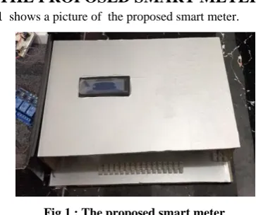
[image:1.595.333.515.464.616.2]Fig 1 shows a picture of the proposed smart meter.
Fig 1 : The proposed smart meter
3.1
The Smart Meter Design
A hardware and software utilized to integrated the design of the presented smart meter; as a software , Arduino C language is used to program the microcontroller , while the hardware component of the smart meter design consist of : Arduino microcontroller, SIM900A GSM shield , LCD Display, current sensor, flame sensor, relays, Buzzer and LED. Fig 2
Fig 2: The general block diagram of the hardware of the presented smart meter design
Each component in the smart meter design will be described in details in the following .The presented meter needs for some setting to start work , the electric provider server will set up the meters before the consumer setup it in his home
3.1.1
The Microcontroller
Arduino Mega Microcontroller (ATmega 2650) is used in this system design, Arduino is an open-source prototyping platform based on easy using hardware and software [4].
[image:2.595.326.532.166.265.2]Fig 3 shows the Arduino mega board which is used in this project .
Fig 3: : The Arduino Mega Microcontroller Unit
In the design of the smart meter circuit , EEPROM is used to save the setting data in microcontroller which are given to the meter from the electric provider server; it is used to save the important data such as : The setting information , balance value , last recharging information , value of the last current which calculated in the meter , unit price value , threshold value.
3.1.2
GSM
Communication
(GSM
Shield
)
GSM technology is a technology behind the Global System for Mobile communication (GSM), the Advantage of using GSM are a wireless communication and security which are the most important aspect for transmitting data , the GSM network that has a wide range to access to an area across the different countries, and also it’s almost the network which has the least impact on human health [5] . For the cost issue of the SMS (Short Message Service) , in this design , the system was assumed that there will be a special telephone sim card for the electricity department to be paid free charge by the government, or an invoice paid by the consumer annually as a cheap bill , these are suggestion to avoid the issues of cost Balance which required for communicating between the sub systems of the proposed system using "GSM technology" . The GSM shield in the smart meter is used to send/ receive
the messages and calls just like a mobile phone by using a SIM card by a provider network .The microcontroller can communicate easily with the shield using the AT commands[6] . (SIM900A) Mini DEV Board module is used in this project as a gateway for data transmitting with the electricity provider server and the consumer's mobile. Fig 4
shows the used SIM900A GSM shields with the power supply which are used to power it.
[image:2.595.332.521.310.468.2]Fig 4 :SIM900A and the used power supply Figure 5 shows the connections of the "GSM" shield with the arduino and the power supply
Fig 5 : The GSM shield wiring with Arduino and power supply
[image:2.595.63.263.398.504.2]AT (for Attention) commands are used to control the GSM shield in order to issue these commands to the serial port, the port should be open and then write AT commands which are listed in Table 1 [7].
Table 1. AT Commands AT meaning
AT Check the communication
AT+CMGF=1 Set the message format to text.
AT+CMGL=”REC
UNREAD” List the unread messages AT+CMGS=\"xxxxxxxxxxx\" Send message
[image:2.595.310.550.545.636.2]but had not been read yet. The next step is to read the data existed on the port and then store it in a variable[9].
3.1.3
The Current Sensor
In this work the Itead TA12-100 current transformer is used to measure the current. The device uses a (1000:1) voltage current transformer. The output of this transformer is shunted with "200 ohm resistor" across its output [9]. The connection of the used current sensor to the" Arduino" is required to:
Connect one of the sensor pin to the analog input A0 of the Arduino and , and the other with the GND of the Arduino, 200 ohm resistor are shunted across the sensor leads , respectively on both ends of the sensor.
[image:3.595.317.554.115.212.2]The current sensor detect the phase current that are pass through the hole of the sensor. Fig 6 shows the current sensor wiring .
Fig 6 : The current sensor wiring
3.1.4
LCD Display
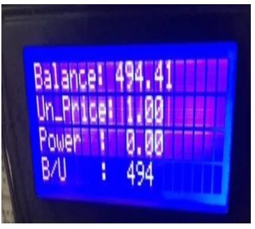
16x4 Character LCD is used to show some information to the consumer , which include (the remainder balance in meter, unit price value, power at time, and the consumed balance at the last minute moment, , Fig 7 shows the meter LCD .
Fig 7 : The smart meter LCD display
led are used in the design to blink and buzzer to beep if the meter receive any message.
For the purpose of adding some protection to the appliance of the consumer buildings in the event of an electrical contact , a flame sensor is connected to the smart meter to sensing the fire.
3.1.5
Relay
A relay is an electrically operated switch used to control a circuit by a separate low-power signal , therefore , the relay is
used to control (switch on/off) the appliances of the consumers' premises according to the Arduino commands [10]. 16 relay pieces are used in the smart meter design. Fig 8
[image:3.595.75.259.260.414.2]Show the relay connection with the home appliances.
Fig 8 : The relay connection with the home appliances
The relay is used to control the home appliances based on a threshold value which is set to meter previously , the meter will use this value to notify the consumer about the meter balance if it is closed to it, and then start to switch off the appliances sequentially based on the set priority based on the meter balance value. That’s mean , if the balance is run out all the appliances is switched off .If the consumer recharged the meter with enough balance again , the relays will switch on all the appliances.
3.3
The Smart Meter Tasks
The tasks of the presented smart meter are:
1. Simplify and help the consumer to pay the cost of the electricity energy to the provider office remotely from any place of the world.
2. Calculate the current that the premises appliance consumed it each one minutes, and subtracts the value of the remainder balance in the meter and show it on LCD display to the consumer.
3. Send the remaining balance value to the EPS each one hour to save the consumer right if any problems occur in the meter..
4. Control and monitor the consumer premise appliance sequentially based on the balance threshold and the programed priority of the appliances .
5. Detect the consumer premises appliances from the closed flame.
6. Help the electric provider server to control (deactivate/activate) any meter if that’s needs for some reasons.
3.4
The Smart Meter Operation
Following details the most important operation of the meter working.
3.4.1
Balance Recharging
After the meter setup in the consumer home , to start meter running , that is need to recharge the meter with enough balance, the consumer can do that by sending the balance card code to the electricity provider as SMS by using phone . The message recharging must contents the meter number , consumer number ,and the balance card code with space between each number , to help the consumer to recharge from any phone nor just his phone , in this way the electricity provider server will specify the meter based on the entered numbers and the entered card code . If the card code was not used previously , the provider will recharge the meter with the required category , else it will replay that the card is unavailable or it have been used to recharge again . For example of the recharging message :
[image:3.595.77.260.484.648.2]the consumer number / the meter number / card code
if the electric provider server will send the balance recharging message to the meter , the meter will add it to the remainder balance and switch on all the home appliances (meter relays).
3.4.2
The consumed current calculation
The smart meter will start to calculate the current that is consumed by the consumer by sensing the current value which pass through the current sensor every one minute.
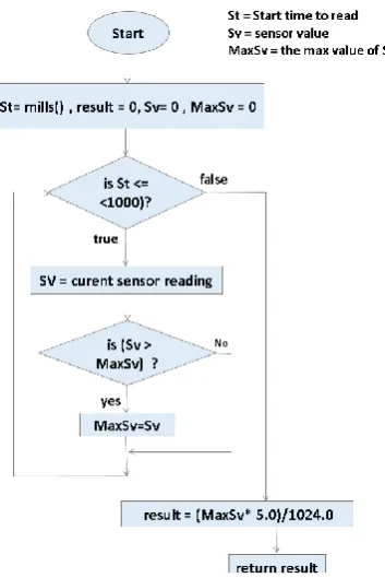
When the meter needs to read the value of the current sensor to calculate the consumed current and balance each one minutes , the meter program will call a function must read the sensor value at that moment by read the value each one millisecond for one second (1000 mills) , and extract the max value to use it to calculate the current at that time. Fig (9)
[image:4.595.99.276.245.510.2]shows this function steps.
Fig 9 : The current calculation function
The current calculation steps are :
1. The result : is refer to the value which the function will return,
2. start time: to counting the millisecond starting with zero, and the max value : is the max value of sensor reading . When the reading process starting , the value of result ,
time start , and the max value are equal to zero .
3. The microcontroller read the sensor value each millisecond and compare the value with the max value . 4. While the time is less than (1 second) go to step (4) , else
skip to step(7).
5. If the reading value larger than the max value , continue , else skip too step (6).
6. Update the maximum value with the larger : (Max value = new sensor reading.)
7. If the St (start time) equal to one second ,continue , else skip to step (10).
Now the last max value will be the result of the function , (the result now is a digital value ) .
8. convert the value to analog (voltage) by multiplied it with 5volt and divided by (1024) digital , the output of this
operation will be the final result of the function which will be return.
( The result now is a volt).
This result : is the value which is used to calculate the consumed current, consumed balance and remainder balance at that time in the calculating balance steps . 9. Exit.
10. Return to step (2).
The result of calculation current step are used to calculate the consumed balance at that time. Fig 10 details the balance calculation steps.
Fig 10 : The Balance Calculations Steps
1. The following steps shows the steps of the balance calculation operation in depth:
2. The Initial value of the result , power is zero . result refer to the value calculated in the current calculation steps which described previously . 3. Calculate the power by multiply it in the voltage
value (220 volt) as in the following equation : 4. Power = 220 * consumed current .
5. The result of this equation is a power in watt per minute .
6. Transform the power in (kwatt / minutes) by divided (Power) on (1000), where (Kwatt = 1000 watt) as in the following equation:
7. Power Kwatt per m = Power/1000.
8. Transform the Power watt per m to (Power in Kwatt per Hour) by divide the (Power watt per m) on 60 , wher (1hour = 60 minute) as in the following equation :
9. Power in Kwatt per Hour = (Power Kwatt per m) /60.
11. The consumed balance = Power in Kwatt per Hour * unit price .
12. Calculate the remainder balance in meter, as in the equations :
13. Remainder balance = Meter balance – Consumed balance
14. Meter balance = Remainder balance.
15. Checkup if the remainder balance (equal to zero) or (equal or less than the threshold value) to switch on/off the required appliances, more details about this step will describe later .
16. Call LCD procedure to show the needs values on LCD display , these values are : The current balance, unit price value, the last consumed balance at the last moment, Fig (4.4) shows a sample of the data display on meter LCD.
17. Check if the balance finish , call a procedure to switch off all the appliance which connected to meter . 18. All These steps will continue to run each one minute
in meter program running.
19. The appliances control and monitoring:
20. When the consumer needs to monitor his home appliances, the following steps will detail this operation:
21. The consumer send SMS to his meter to ask it about the current state of the appliances .
22. The meter will scene the connected relay , and give 0 for the appliance which switched off and 1 for the appliances which switched on, and collect these 0s and 1s .
23. The meter replay the consumer is a clear SMS to notify him about the state, for example of this operation :
(1111111100000000) : in this example the first eight appliances is switched on and the others is switched off. The consumer can switch on/off the appliances by send SMS in the same way to the meter , and the meter will do the required.
4.
CONCLUSION
The system design is utilized to simplify the operation of the electric service billing payment. This design is proposed to solve the problems which are resulted from the traditional billing .its simplify to recharge the meter balance and to control and monitor the home appliance remotely by the consumer mobile using SMS. Its calculate the consumed power. in order to calculate the consumed balance and reduce the consumed balance from the remaining balance in meter , based on the current unit price value. The meter give a
notification to the consumer about any new activity which may occur in it , such as : the balance recharging, the balance turn off, unit price value updating , flame detection
,etc.. As any IoT application
,
this design will simplify thehuman life.
5.
REFERENCES
[1] Hariharan R. , "Design Of Controlling The Smart Meter To Equalize The Power And Demand Based On Virtual Instrumentation", (ICPEC) , 2013.
[2] Atheena Ch., Janardhanan R., S Ashok , "Development Of Inbuilt Energy Management Controller For Smart Meter" , IEEE , 2014.
[3] Swati A., Mulay G. N., Arti K. , "Design And Implementation Of Smart Three Phase Energy Meter, International Conference On Smart Grid And Clean Energy Technologies" ,IEEE, 2016.
[4] R. Subhi,M. Zeebaree, M. Yasin , "Arduino Based Remote Controlling For Home: Power Saving, Security And Protection" , International Journal Of Scientific & Engineering Research, Volume 5, Issue 8,August-2014.
[5] ZHU Yao-Lin, LI Rong, LIU Xue-Bin, Xu Jian , Wireless Communication Technology In Family Health Monitoring System , IEEE, 2011.
[6] K.Prachee, K.Tayade, P.Akash, T.Rajkishor, "GSM Mobile Phone Based LED Scrolling Message Display System" , International Journal Of Scientific Engineering And Technology (ISSN : 2277-1581), Volume 2 ,1 April 2013.
[7] N.Sumita, K. Bakade, S.Parmar , H. Yadav, "Integrated Vehicle Tracking System", (ICRTITCS - 2012) , (IJCA) , 2012 .
[8] R. Dwijen , D. Smita , P. Goutam, , "SMS Based Load Shedding Period Control System, International Journal Of Computer Applications" , September 2011.
[9] N. Mavrikakis, I. Androulidakis, D. Pylarinos , K. Siderakis ," A Labview Based Leakage Current Monitoring System For HV Insulators" , Journal Of Engineering Science And Technology Review , 2015 .