Decentralized Control for Multichannel Active Vibration Isolation
Sang-Myeong Kim, Stephen J. Elliott, and Michael J. Brennan
Abstract—This paper describes a theoretical and experimental investigation into an active four-mount vibration isolation system, in which electromagnetic actuators are installed in parallel with each of the four passive mounts placed between a three-dimen-sional piece of equipment and a vibrating base structure. Decen-tralized velocity feedback control is applied, where each actuator is operated independently by feeding back the corresponding equip-ment vibration velocity at the same location. Although one end of the actuator acts at the sensor position on the equipment, the system is not collocated because of the reactive force at the other end acting on the flexible base structure, whose dynamics may be strongly coupled with the mounted equipment. The investigation of this actuator installation and its practical implementation are the motivation of this research. Isolation of low-frequency vibra-tion is considered where the equipment can be modeled as a rigid body and the mounts as lumped-parameter springs and dampers. A general theoretical formulation for analysing multiple-mount vi-bration isolation systems using the impedance method is presented and is used to investigate the control mechanisms involved. Experi-mental results show that up to 14 dB reduction in the kinetic energy of the equipment can be achieved in practice. If very high gains are used in the experiments, however, instability occurs at low frequen-cies due to phase shifts in the transducer conditioning electronics.
Index Terms—Active isolation, decentralized control, velocity feedback, vibration control.
I. INTRODUCTION
A
NTIVIBRATION mounts (also called isolators) are often used to protect delicate pieces of equipment from the vi-bration of the structure that they are attached to. With conven-tional passive mounts, however, there is a tradeoff between low-and high-frequency isolation performance, which depends on the damping in the mounts [1]. Thus, it is useful to introduce additional vibration sources that can actively reduce vibration transmission through the mounts at all frequencies [2], [3]. Al-though such active isolators may be constructed by feeding back all the state variables, as commonly seen in active suspension systems [4], [5], a simpler method may be to use direct output feedback control using the velocity responses of the structure to be isolated. When force actuators are placed in parallel with the isolators and they are collocated with the sensors then if the base structure behaves as a rigid body, the multichannel decen-tralized control system constructed by linking each collocated pair is passive and hence asymptotically stable [6], [7]. In this case, the control gains used can be analogously transformed to virtual mechanical skyhook dampers [8]. An experimental studyManuscript received September 14, 1999; revised July 5, 2000 and August 28, 2000. Recommended by Guest Editors S.O. R. Moheimani and G. C. Goodwin. S.-M. Kim is with the Department of Mechatronics, Kwang-Ju Institute of Science and Technology, Puk-gu 500-712, Korea (e-mail: [email protected]).
S. J. Elliott and M. J. Brennan are with the ISVR, University of Southampton, Southampton SO17 1BJ, U.K.
Publisher Item Identifier S 1063-6536(01)00420-1.
using this idea has recently been reported with a two-mount ac-tive isolation system [9].
The work presented here describes a theoretical and ex-perimental investigation into an active four-mount vibration isolation system in which electromagnetic actuators are in-stalled in parallel with each of four passive mounts placed between a three-dimensional piece of equipment and a flexible vibrating base structure. Decentralized velocity feedback
control is applied [10], [11], where each actuator is operated independently by simply feeding back a signal proportional to
the corresponding equipment vibration velocity at the same location. Although one end of each actuator is collocated with each sensor on the equipment, the system is not collocated in the sense of [6], [7] because of the additional noncollocated reactive force at the other end acting on the flexible base structure which is also a part of the plant. When this is strongly coupled with the mounted equipment, the passivity property [6], [7] of collocated control is not strictly applicable. This practical configuration is investigated in the current paper, with particular emphasis being paid to the control mechanisms and stability. The impedance method [12] is used for the mechanical analysis of both passive and active vibration isolation systems. Isolation of low-frequency vibration is considered where the equipment can be modeled as a rigid body and the mounts as lumped parameter springs and dampers. The simple decentral-ized direct velocity feedback control system presented here could be applied to the active vibration isolation of delicate equipment, such as the instrument boxes in aeroplanes and telescopes in satellites, etc.
The basic concepts and mechanisms of velocity feedback control using the structural-borne actuator are discussed in Sec-tion II initially with a single-mount vibraSec-tion isolaSec-tion system. The analysis is extended to a general four-mount system in Section III, and experiment results are reported in Section IV. Potential causes of instability in practical implementations are also discussed, before the paper is concluded in Section V.
II. ACTIVEISOLATION OF ASINGLEMOUNTSYSTEM
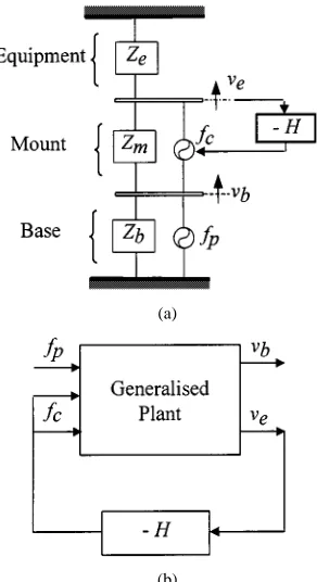
Consider a single mount isolation system where a piece of equipment is connected to a flexible base structure via a single mount. If the mount is assumed to be massless, the whole system can be represented in terms of mechanical impedances as shown in Fig. 1(a) where and denote the impedances of the equipment, mount, and base, respectively. The base struc-ture with velocity is excited by a primary force , and direct velocity feedback control is applied to reduce the equipment ve-locity using a pair of control forces via the controller with a gain . The force pair models the action and reaction of a single electromagnetic control actuator installed in parallel with
(a)
[image:2.612.92.238.62.330.2](b)
Fig. 1. (a) Impedence diagram and (b) block diagram of a single mount vibration isolation system.
the mount. It is convenient to interpret the mechanical system as a coupled one connecting the mounted equipment and the base structure, where the mounted equipment is the combination of the equipment and the mount. The impedance diagram can also be represented as a block diagram as shown in Fig. 1(b) where the generalized plant has three inputs and two outputs.
If the total force acting through the mount is , then the dynamic equations of the mounted equipment can be written in the frequency domain as
(1)
(2)
and the dynamics of the base structure can be described by
(3)
The system can also be represented in a matrix form as
(4)
When direct velocity feedback control is applied, the control force is given by
(5)
where is restricted here to be a positive control gain. Incorpo-rating (5) into (4) gives the active system written in a compact matrix form as
(6)
Note that, because of the term representing the influence of the reactive force acting on the base, the impedance matrix of the complete active system is nonsymmetric. This nonsym-metric term means that the stability of the system can not be assessed by simply using the definiteness property (positive or negative) of the impedance matrix as in collocated control [6], [7]. In addition, the mechanical analogy of a skyhook damper [8] is no longer a correct interpretation, as far as the dynamics of the complete coupled system is concerned. Here, the active system is temporarily assumed to be stable to investigating the control mechanisms involved, so that the responses
can be obtained simply by inverting the system impedance ma-trix.
The transmissibility is often used as a measure of control per-formance, which is given by [8]
(7)
Equation (7) suggests that, as far as the relative vibration of the equipment to the base is concerned, rather than or alone, the feedback control system acts like a skyhook damper. Note that the base impedance does not appear in (7). Transmis-sibility is a good performance measure for a mounted equip-ment that is weakly coupled to the base [12]. If strongly cou-pled, however, the base velocity changes after the attachment of the mounted equipment and also after the feedback controller is implemented.
If the feedback gain used is very large so that
in (7), the transmissibility is greatly improved, i.e., . The control force in this case becomes
(8)
For an infinite gain this is the perfect control force for a hypo-thetical feedforward controller given perfect knowledge of and . If the control force is applied, (6) becomes
(9)
where . With perfect control of equipment vibration the base would behave as if no mounted equipment were attached, showing that the control force pair uncouples the mounted equipment from the base. In practice this can only be achieved approximately.
We now examine stability of the single mount system shown as a generalized block diagram in Fig. 1(b). By inverting the passive impedance matrix in (4), the equipment velocity is
(10)
where the frequency response of the plant is given by
(11)
and the disturbance is
in which . If velocity feedback control is applied so that , then the equipment velocity is
which is the typical form for a disturbance rejection problem. Similarly, the base velocity after feedback can be obtained as
(13)
The control system is unconditionally stable with respect to the control gain if the plant response does not cross the negative real axis, i.e.,
or (14)
at all frequencies. Here denotes the real part. Because of the passivity of the impedances of mechanical elements, i.e., and , the condition in (14) is de-termined by the third term of the denominator in (11). Thus the required stability condition can be rewritten as
(15)
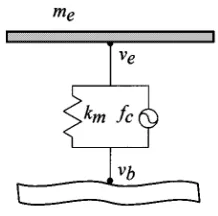
The equipment structure is now modeled as a free-free flex-ible beam of total mass and length that is installed on an arbitrary flexible base structure via a mount modeled as a single spring of impedance as shown in Fig. 2. If we ignore all the flexible modes higher than the first, the
equipment impedance is given by , where
is a nondimensional variable [13]. Here is the first angular natural frequency of the flexible beam and is the squared value of the first mode shape function at the mount point, . For simplicity, damping in the equipment and the mount is ignored. It is important to note
that at low frequencies where is
pos-itive so that the equipment impedance is mass-like and behaves as a rigid body. Equation (15) in this case becomes
(16)
Since the real part of the base mobility is always nonnega-tive, (16) is satisfied for . If the equipment is completely rigid, i.e., so that , (16)
becomes and is valid at all frequencies.
In this case, the Nyquist locus looks similar to the mobility of a single degree of freedom (DOF) vibration system, and is al-ways in the right half of the complex plane. If a small amount of damping is included in the mount, the original locus shifts in the clockwise direction, but still approaches the origin as the frequency increases without crossing the negative real axis. An important conclusion from this analysis is that the system is un-conditionally stable with respect to the control gain regardless of whether the actuator installation is grounded or not, provided the equipment is rigid and is supported upon a massless mount. It should be emphasized that no assumption has made about the base dynamics to draw this conclusion. Under these idealized conditions, the active isolation system shown in Fig. 1 has
collo-cation control-like behavior (unconditionally stable and perfect
[image:3.612.371.480.60.168.2]controllability) and its plant shows driving point mobility-like behavior (no crossover of the negative real axis of the Nyquist plot).
Fig. 2. One DOF equipment structure mounted on a flexible structure.
III. ACTIVEVIBRATIONISOLATION OF AMULTIPLE-MOUNT SYSTEM
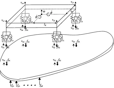
Extending the single mount system to a four-mount system with a three-dimensional (3-D) piece of rigid equipment results in the system as shown in Fig. 3. The impedance approach de-scribed in the previous section can also be applied to this general case but with some care because of the difference between the numbers of mounts (four) and DOFs of the equipment structure (which is now assumed to move as a rigid body and so has only three DOFs). The coordinate transformations between the phys-ical coordinates at the mounting points and modal coordinates are given by
(17, 18)
where is the modal velocity vector consisting of the derivatives of heave, pitch, and roll motions at the mass
centre, and is the velocity vector at
the mounting points. Since (17) is over-determined, the
pseudo-inverse of is give by [14], [15]. The
dynamic equations can be described in a similar way to those for the single mount system given in (1)–(3). By extending (4), the system equations can be written as
(19)
where the modal impedance matrix of the equipment is in which is the diagonal inertia matrix of the equipment whose diagonal terms are the mass of the equipment , and the moment of inertia quantities to pitch and roll motions and . The bar notation is introduced to signify a matrix in the modal rather than the physical coordinates of the equipment. is a (4 4) diagonal matrix whose diagonal terms are the impedances of each mount, is the control force vector
in which and are the impedance and mobility matrices of the uncoupled base structure.
The generalized control force vector is , and is the modal mount impedance matrix which is the transformed form of the physical matrix to the equip-ment modal domain [14], [15]. When velocity feedback control with the control gain matrix is applied, i.e., , using the properties and gives the trans-formed gain matrix as
Fig. 3. A 3-D rigid equipment structure supported upon four mounts.
Again the controllers are restricted to be frequency independent constants. The complete dynamics of the active system can now be written as
(21)
Equation (21) is a compact description of the four-mount active vibration isolation system in terms of impedances. Note this is also a simple extension of the form given for the single mount system in (6). If the perfect control force vector
is applied, it uncouples the mounted equipment from the vi-brating base structure so that the active system becomes sim-ilar to (9). The solution of (21) can be obtained by inverting the impedance matrix, provided the system is stable. The kinetic en-ergy for the 3-D equipment structure can be conveniently em-ployed as a performance measure, and is given by
(22)
Consider a simplified control system where four separate single-channel control systems are used by connecting each collocated pair of the actuators and sensors, instead of a general four-channel control system with a fully populated gain matrix . This is termed decentralized control [10], [11] where each of the four actuators is controlled independently by feeding back the corresponding equipment vibration velocity response at the same location. In this case the control gain matrix becomes diagonal. We investigate the active system shown in (21) when this simplified control strategy is applied. If the system shown in Fig. 3 is assumed to be statically balanced, which means the
impedances of each mount are the same, , for a symmetric equipment structure, then becomes diagonal. If we further assume that the four gains of each controller are the same, , the (3 3) matrix in the term of (21) giving the equip-ment dynamics in modal coordinates also becomes a diagonal matrix whose diagonal terms are
and . Here is the
dis-tance between the mass centre of the equipment and the mount in pitch motion, and in roll motion can be similarly defined. Note, as in the single mount case, the control gain is simply added to the mount impedance in all three modal motions. For the statically balanced symmetric structure shown in Fig. 3, decentralized control using the same gains (equidecentralized
control) thus results in a modal controller, which equally damps
all modes (equimodal control). Each of the four gains acts like a skyhook damper, as far as the relative equipment vibrations are concerned as discussed in Section II. The analysis can now be extended to the general case of a nonsymmetric equipment structure, but whose installation is again assumed to be statically balanced as is preferred in practice [1], in which case equimodal control can again be achieved by making the modal control gain matrix diagonal, and similar to .
from the open-loop frequency response function matrix written as . The generalized Nyquist criterion states that the closed-loop system is stable if and only if none of the eigenvalue loci of should encircle the point in the complex plane [10]. More specifically for equidecentralized
control, i.e., , then , and none of
the eigenvalue loci of should encircle the point for stability, and none of the eigenvalue loci should cross the negative real axis for unconditional stability. Since one of the responses in is linearly dependent on the others and thus one of the eigenvalues is zero, it is convenient to judge the criterion in the transformed coordinates
(23)
where denotes the eigenvalues.
Now we examine a particular case when the coordinate trans-formations are fully determined, i.e., in (17) is square and in-vertible, such as the two mount system with a two-dimensional equipment and the three mount system with a three-dimensional equipment. In this case, analysis of the stability condition given in (23) is greatly simplified. The transform matrix in (18) is now can be written as , and the same coordinate trans-form relations can also be applied to the base velocity vector as and , where is the transformed base ve-locity vector. In this case the plant matrix is given by
(24)
where , in which the transformed base impedance is . Note that this is also a simple extension of the form for the single mount system in (11). Again a rigid equipment and massless mounts are assumed together with the statically balanced installation of a symmetric equipment. Note, however, no assumption has made on the base dynamics. In a similar way to the single mount case given in (14), a satisfactory condition for unconditional stability using (23) can be written as
(25)
at all frequencies. Here , and are diagonal, and is symmetric but nondiagonal. The condition can be
deter-mined by examining . Because
of passivity, then and ,
and the stability of the system is determined by the last term
, where again due to the
passivity. If we assume that there is no damping in the mounts, then the diagonal matrix has elements which are positive real and similar to that for the single mount system.
Thus , and consequently the real
eigenvalues of the plant in (25) become nonnegative at all
frequencies so that . As in the case
of the single mount system, damping in the mounts does not threaten the unconditional stability. However, if the equipment structure is flexible within the frequency range of interest, then is no longer positive. Thus the decentralized control system is only unconditionally stable, provided the equipment behaves as a rigid body and the mounts act as springs and dampers.
When the system is over-determined as in the four-mount system in Fig. 3, there is a redundant passive mount and a re-dundant active force. It is thus no longer possible to apply the convenient transforms and for the base re-sponses. The analytical plant matrix expression may still be ob-tained from using (19), but becomes very complex in this case. Its analytical proof is thus not given but instead some supporting simulation and experimental results are reported in the next sec-tion.
IV. EXPERIMENTALIMPLEMENTATION
A. Control Performances
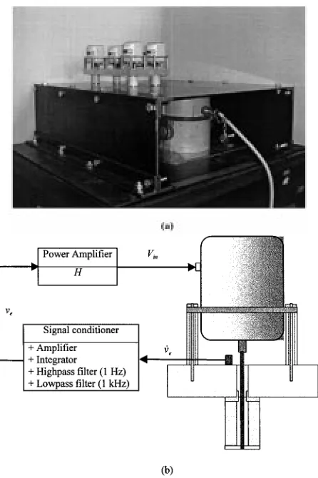
Decentralized direct velocity control was experimentally implemented with a statically balanced symmetric four-mount system similar to that shown in Fig. 3. The experimental setup is shown in Fig. 4(a) where a symmetrical aluminum block ( mm) representing the equipment is installed on top of a free-free-clamped-clamped steel base plate of ( mm) via four identical mounts, each of stiffness N/m and damping Ns/m. To realize the clamped-clamped boundary conditions, two opposite sides of the base plate were bolted on stiff frames. The large shaker underneath the plate acted as the primary force actuator, and the four small electromagnetic actuators fixed on the thick equip-ment plate were the control actuators at each mount position. The equipment to be isolated was thus a combined structure of the four actuators and the aluminum block, of thickness 20 mm, whose inertial values were kg,
kgm , kgm . Fig. 4(b) shows the structure of decentralized control for a single channel. Each actuator was fixed on top of the thick equipment plate at each mount location, and a stinger was connected between the actuator and the mount foot through the hole of the cylindrical mount, which was made from natural rubber. The equipment acceleration at the mounting point was measured and passed through an integrator to obtain the velocity response , which was then fed back to the actuator via a power amplifier with gain control. The integrator was contained in a commercial charge amplifier (B&K type 2635) which also had high- and low-pass filter modules. The highpass filter cutoff frequency was set to be 1 Hz to avoid DC signal overflow, and the low-pass filter cutoff frequency was set to be 1 kHz to filter out any measurement of flexible modes within the equipment structure. Only isolation of low-frequency vibration under 200 Hz was considered, so that the equipment structure could be modeled as a rigid body and each mount as a parallel connection of spring and damper , as shown in Fig. 3.
Fig. 4. (a) Experimental arrangement in which an aluminum block, to which the secondary actuators are attached, is supported on a steel plate by four active mounts and the steel plate can be vibrated with a large shaker. (b) The structure of a single active mount.
denote the loci of the pitch and roll modes, respectively. The experimental loci in Fig. 5(b) are very similar to the theoretical ones in Fig. 5(a), but it is difficult to judge whether or not they really cross the negative real axis near the origin, especially at frequencies less than 5 Hz, where the data was of low coherence due to the low sensitivity of the actuators and sensors used. Zooming into the origin of the simulation plot showed that none of the eigenvalue loci cross the negative real axis, which is evidence that the redundancy of one actuator in the four-mount system does not threaten stability. Although not shown here, the use of three actuators was also examined both theoretically and experimentally and showed a similar result [13].
The four-channel decentralized control system whose single channel structure is shown in Fig. 4(b) was then tested. The con-trol performance was measured with four equal gains in the power amplifiers and compared with simulations. The equip-ment velocity at the mounting points was measured and then transformed to modal responses using (18) to calculate the total kinetic energies in (22), which was used to quantify the con-trol performance. The total kinetic energy calculated from the simulation model and measured in the experiment is shown in Fig. 6(a) and (b), respectively. In Fig. 6, the response before control is shown with solid lines and those after control are shown with dashed lines. The highest response (solid line) is the total kinetic energy before control, and the others (dashed
(a)
[image:6.612.317.541.63.443.2](b)
Fig. 5. (a) Predicted and (b) measured Eigenvalue loci of the plant on the flexible base structure; heave (solid), pitch (dashed), and roll (dotted).
(a)
(b)
Fig. 6. (a) Predicted and (b) measured total kinetic energies of the equipment structure with various feedback gains H; without control (solid) and with control (dashed). (dB ref.=10 J)
accounting for the amplification region. Both simulation and ex-periment results show a kinetic energy reduction of more than 14 dB for a feedback gain 1000.
In order to explore the control mechanisms discussed above, a base velocity was also calculated and measured during control. The simulation and experimental results are shown in Fig. 7(a) and (b), respectively. As the gain increases, the original base response (solid line) approaches the uncoupled base response (dotted line), that is the base response without the mounted equipment attached. The dashed lines correspond to the base re-sponses for each control gain. These results clearly demonstrate that the active isolation system tends to uncouple the mounted equipment from the base structure.
B. Causes of Instability in the Practical System
The cause of the instability in the experimental plant was found to be phase advances in the power amplifier and the inte-grator [13]. The commercial amplifier had a phase advance up to about 90 at very low frequencies (under 5 Hz). Furthermore, an additional phase advance occurred in the commercial charge amplifier used for integration. A phase advance of greater than
TABLE I
COMPARISON OF THECONTROLPERFORMANCES, WHEREc = 25:6 Ns/ms IS THEDAMPINGVALUE OF THEPASSIVEMOUNTS
(a)
(b)
Fig. 7. (a) Predicted and (b) measured base response at the bottom of mount 1 for various feedback gainsH; without control but coupled (solid), uncoupled (dotted), and with control (dashed).
90 at very low frequencies can cause the eigenvalue loci to cross the negative real axis, and thus make the system unstable to a high gain. Such phase advances, which were not accounted for in the simulations, were the cause of the instability in the experiment.
the signal conditioner causes an effective time delay on the con-trol loop, which can make the system unstable at very high fre-quencies [13]. Furthermore, the phase shift in the electromag-netic actuators can also be modeled as an additional time delay [16]. In the experimental plant considered, the equivalent delays were measured to be approximately 0.2 ms for the filter and 0.04 ms for the actuator, but the magnitude of the plant response had fallen off sufficiently at frequencies where these delays caused significant phase shift that the stability was not compromised. The system can also be unstable due to mechanical causes, par-ticularly when the flexible modes of the equipment becomes im-portant and when the mass of the mounts becomes significant. In the experimental plant, the first flexible mode of the equip-ment plate was at about 1240 Hz, and the first longitudinal mode of the rubber mount was at about 500 Hz [13], which were both well above the frequencies at which good active performance would be expected in this application.
V. CONCLUSION
This paper has investigated both theoretically and experi-mentally a four-mount active vibration isolation system where electromagnetic actuators are installed in parallel with each of four mounts placed between a piece of equipment and a vibrating base structure. Decentralized velocity feedback control was used to actively achieve low-frequency vibration isolation.
A general formulation using the impedance approach was presented to analyze passive and active multiple isolation sys-tems. This facilitated both an understanding the physics of vi-bration isolation and investigations into the control mechanisms involved. It was demonstrated that the decentralized velocity feedback controller tends to uncouple the mounted equipment from the base structure. It was shown that the system is uncon-ditionally stable with respect to the control gain provided that the equipment is rigid and the mass effect of the mounts is neg-ligible. Experimental results show that up to 14 dB reduction in the kinetic energy of the equipment can be achieved in practice. When very high gains were used, however, instability was en-countered in the experimental rig at about 1 Hz due to undesir-able phase advances of over than 90 in the electrical equipment used.
Although the performance of the control system could be im-proved by implementing a fully coupled feedback system and by using a frequency dependent controller, the decentralized con-trol system with constant feedback gains is very simple to im-plement and performs well in this application. It also has the advantage that very few assumptions have to be made about the dynamics of the system under control, and so the stability and performance of the control system is very robust to the kind of changes which may occur in these dynamics under operating conditions.
REFERENCES
[1] C. E. Crede and J. E. Ruzicka, “Theory of vibration isolation,” in Shock
and Vibration Handbook, C. M. Harris, Ed. New York: McGraw-Hill, 1996, ch. 30.
[2] L. Meirovitch, Dynamics and Control of Structures. New York: Wiley, 1990.
[3] C. R. Fuller, S. J. Elliott, and P. A. Nelson, Active Control of
Vibra-tion. New York: Academic, 1996.
[4] D. Hrovat and M. Hubbard, “Optimal vehicle suspensions minimizing RMS rattlespace, sprung-mass acceleration and jerk,” J. Dyn. Syst.,
Measurement, Contr., vol. 103, pp. 228–236, 1981.
[5] A. Hac, “Stochastic optimal control of vehicles with elastic body and active suspension,” J. Dyn. Syst., Measurement, Contr., vol. 108, pp. 106–110, 1986.
[6] M. J. Balas, “Direct velocity feedback control of large space structures,”
J. Guidance Contr., vol. 2, pp. 252–253, 1979.
[7] S. M. Joshi, “Robustness properties of collocated controllers for flexible spacecraft,” J. Guidance Contr., vol. 9, pp. 85–91, 1986.
[8] D. Karnopp, M. J. Crosby, and R. A. Harwood, “Vibration control using the semiactive force generators,” J. Eng. Ind., pp. 619–626, 1974. [9] M. Serrand, “Active Isolation of Base Vibration,” M.Sc. thesis, Univ.
Southampton, 1998.
[10] S. Skogestad and I. Postlethwaite, Multivariable Feedback Control;
Analysis and Design: Wiley, 1996.
[11] M. Morari and E. Zafiriou, Robust Process Control. Englewood Cliffs, NJ: Prentice-Hall, 1989.
[12] S. M. Kim and M. J. Brennan, “A compact matrix formulation using the impedance and mobility approach for the analysis of structural-acoustic systems,” J. Sound Vibr., no. 223, pp. 97–113, 1999.
[13] S. M. Kim, S. J. Elliott, and M. J. Brennan, “Active vibration isolation of a 3-D structure using velocity feedback control,”, ISVR Tech. Memo. 845, 1999.
[14] B. Noble and J. W. Daniel, Applied Linear Algebra. Englewood Cliffs, NJ: Prentice-Hall, 1988.
[15] F. B. Hilderbrand, Methods of Applied Mathematics. Englewood Cliffs, NJ: Prentice-Hall, 1965.