SCENE MANAGEMENT FOR MODELLED AUDIO OBJECTS IN
INTERACTIVE WORLDS
Dylan Menzies
Zenprobe Technologies
[email protected]
ABSTRACT
The acoustic behaviour of natural objects and their interactions can be accurately recreated in interactive world simulations. A realistic simulation may contain many such objects, any combination of which may be interacting at a given time. High and low level structures are presented for managing this complexity efficiently and with flexibility, based upon an existing PC system.
1. INTRODUCTION
There has been a growing interest in the simulation of sounds in interactive worlds, using models that are precisely stimulated by dynamical interactions in the world. This adds a new level of immersion to the interactive acoustic experience. The field can be traced back to the work of Hahn [1], in which impact sounds between graphically rendered objects were modeled with modal resonators. Van den Doel [2, 3] expanded this to continuous contact excitations depending on contact forces and surface properties. O’Brien employs finite element techniques to simulate object resonance, [4]. While in principle this offers the ability to simulate resonance from detailed material and geometric data, it is much more costly than other less explicit resonator models, such as modal resonators, and lacks the capability of being fitted to recordings, as described by van den Doel.
A wide range of interesting acoustic phenomena can be captured using the model of impacts, continuous interactions between solid objects and resonance, forming the basis for the present work. Of course there are many phenomena that are not covered by this model, for instance the splashing of liquids or the howling of wind. Providing a good structure for the more restricted case will hopefully lay a solid foundation for future developments.
One barrier to the wider adoption of these techniques has been the lack of a coherent system for efficiently and dynamically structuring large numbers of acoustically interacting objects, as might typically be required to complement a 3D interactive world system. The problem is analogous to a 3D renderer that must coordinate all the object information to produce the final image. Existing virtual reality audio systems have focused on providing flexible interfaces and support for room acoustics and spatialization, [5,6,7]. The system described here introduces new structures and techniques for managing interacting objects.
Here are some of the issues that appear at the outset: 1. How should the interface be designed to enable the
creation and maintenance of an interactive acoustic world? In real-time, efficiency is very important, but flexibility to
cope with ever-changing and widely differentiated scenes is important too.
2. There may be many objects that could make sound, but at any time most may be quiet.
3. Collisions are short-lived, so collision resources should be shared.
4. Continuous contact should be handled separately from impacts. For instance we might have to inform the system when a contact finishes, but an impact should schedule its own termination.
This paper describes the structure of a fully implemented system,1 that addresses these problems of scene management. The system was integrated with a high performance dynamics and collision engine2.
We start with a look at the main data structures, then describe the user interface, and finally the engine that generates the sound output.
2. OVERVIEW OF STRUCTURES
The data structures used are naturally object-oriented, and so are described well by languages such as java and C++3.
Briefly, for those unfamiliar with object-oriented terminology, a class is a data type, instances of which are objects. Classes have associated methods or functions, and each object can have its own internal variable space. An abstract class cannot have instances of its own, but rather is a base for more specific classes, with additional methods, that can.
In the following discussion the controller will refer to the system that is communicating simulation-time information about dynamical events to the acoustic scene manager or ASM. This will normally take the form of an interface layer sitting between the dynamics and collision engine and the ASM.
2.1. Principle Classes
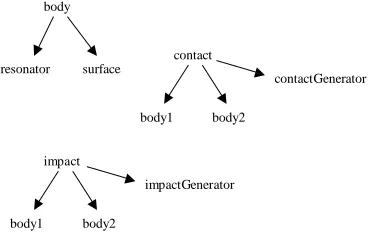
The highest level classes are body, contact and impact. Refer to Figure 1. It shows how principle objects refer to each other using pointers. Body contains everything needed to generate sound from a physical object. It references two objects. The first is of abstract class resonator, and the second abstract class surface. Keeping these classes abstract enables a variety of specific resonator and and surface models to be interchanged freely through a common basic interface. If a new model is
1
MeAcoustics 1999-2000, Mathengine plc.
2
Downloads will be made available at
www.zenprobe.com/pub3
introduced it can be quickly added without any changes to the overall structure.
body
resonator surface
contact
body1 body2
contactGenerator
impact
body1 body2
impactGenerator
Figure 1. Pointers between principle objects
Specific resonator classes contain models for the object resonance, for instance using modal synthesis. So a resonator object contains all the state for the resonating process. It may be shared by several bodies, see Figure 2, which is unphysical, but useful for economizing in situations where large numbers of similar acoustic objects are interacting, for examples marbles in a jar. A specific surface class contains parameter settings for the surface, and a pool of specific associated generator objects, which it manages. When two surfaces come into contact, their respective surface objects activate new generators. In this way a single surface can be interacting with several other surfaces at once.
body1
resonator body2
[image:2.612.95.281.81.200.2]body3 body4
Figure 2. Multiple references to a resonator Contact and impact objects are used to contain information about currently active collision events. Because collisions are rapidly starting and ending, object resources are held efficiently in pre-initialized pools. Contact objects are used by the controller when object dynamics indicate that the two surfaces will remain in contact for a while, and impacts are used when the objects are briefly in contact for one integration step and impulse information is available. Contacts must be continuously updated with contact force and speed information, and must be deactivated once the collision system detects separation, to free resources. Impacts on the other hand, are automatically deactivated once the excitation signal has been generated. This signal depends only on the initial dynamic information.
2.2. Specific Classes and models
The only specific surface class currently available is segmentSurface. This is associated with a segmentContactGenerator for continuous contact, similar to
that described by van den Doel, in which the contact point behaves like a gramophone needle running over the two surfaces, with added low pass filtering. The cutoff frequency is lowered as the relative speed of the surfaces at the contact point decreases, reflecting the decreasing energy of the interaction. When the objects are ‘rolling’ relative to one another, this speed is zero, and the filter cutoff attains a minimum. A segment object is a holder for an audio recording. These are used by segmentContactGenerator to describe the surface ‘relief’.
Likewise a segmentImpactGenerator class is defined for impacts. This generates a pulse according to the combined ‘hardness’ of the two surfaces and the impact impulse. A harder impact produces a shorter pulse, and the impulse determines the amplitude. The expression for hardness can be derived from a simple elastic collision model. If
γ
1,γ
2are the spring constants, measuring hardness, of the two surfaces, then the combined effective spring constant is(
γ
1−1+
γ
2−1)
−1. As expected, the surface is at least as 'soft' as the softer of the two surfaces.As a further refinement a segmentImpactGenerator can generate a ‘skid’ sound by briefly deploying a segmentContactGenerator object, initialized with contact speed and impulse data. This models the way the surfaces will slide past each other for a short time during the impact. For example, a ball bounced off a static surface will skid more the faster it spins. This helps greatly to enliven and add realism to impacts, which may form a large proportion of the collision events occuring.
ModalResonator is a specfic resonator class using modal synthesis. It points to a modalData object containing a list of modes that model a particular object. Several modalResonators might share the same modalData.
Many other existing resonator models could readily be incorporated. A sister paper discusses the perceptual resonator, a resonator model for efficient diffuse resonance based upon perceptual modelling.
segmentSurface
segment modalResonator
modalData
Figure 3. Pointers between specific objects
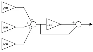
2.3. Collision Signal Flow
[image:2.612.144.220.393.447.2]gen1
gen2
res1
res2
[image:3.612.79.292.59.189.2]gain settings dynamic info
Figure 4. Contact and Impact signal flow
3. THE APPLICATION INTERFACE
The overview has introduced the main structures. Now we present the application interface, simplified for readability. It includes initialization functions, some of which might be directly used by the application developer, and run-time functions that are more likely accessed by an integration layer that sits between the ASM and the dynamics and collision systems. This should help clarify the ASM operation, and introduce some more detailed features. Many of these functions are public methods of the Classes. Enquiry functions have mostly been omitted. The usual C-like syntax applies: () contain function parameters, return values are written at the head of the function and <class>* indicates a pointer to an object.
3.1. Body:
The following are all called during initialization. Once a body is created its parameters can be set. The resonator and surface can be to any specific object (modal, segment). The gain settings correspond to those indicated in Figure 4.
body *create(); destroy(body *);
setResonator(body *b, resonator *r); setSurface(body *b, surface *s);
setContactMasterGain(body *b, float g);
setContactToOtherResonatorGain(body *b, float g); setContactDirectGain(body *b, float g);
setImpactToOtherResGain(body *b, float g); setImpactDirectGain(body *b, float g);
The final two body methods can be used to conveniently switch the acoustic behaviour of an object on or off during runtime, useful if switching context form one scene to another.
bodyEnable(body *b); bodyDisable(body *b);
3.2. resonator:
First global functions for managing the activation of specific resonators.
activationManagerInit(int n); activationManagerGetNumInUse(); activationManagerGetNumUsed();
Now the abstract base methods. The quiet-level determines the sound level at which the resonator will automatically be silenced and deactivated. For the modal resonator this method is implemented for efficiency just by monitoring the amplitude of the lowest mode from its state. A resonator can be forced quiet manually when changing context. Auxilliary scale factors are useful for special effects, for instance linking pitch to body deformation to simulate dynamically varying resonance frequencies.1 SetMaxContactDamping limits the accumulated damping from multiple surfaces touching a body.
resDeactivate(res *r);
resSetQuietLevel(res *r, float l); resMakeQuiet();
resSetAuxAmpScale(res *r, float s); resSetAuxFreqScale(res *r, float s); resSetAuxDampScale(res *r, float s); resSetMaxContactDamping(res *r, float d);
3.3. modal:
ModalData is the initialization data type used by the specific modal resonator. It contains all the mode amplitudes and decay factors.
modalDataCreate();
modalDataDestroy(modalData *d);
modalDataReadDatafile(modalData *d, const char *filename);
modalDataGetNumModes(const modalData *d);
Here are the modal resonator methods. Sometimes it is useful to limit the number of modes used in some standard modal data set.
modalRes* modalResCreate(); modalResDestroy(modalRes *r);
modalResSetData(modalRes *r, const modalData *d); modalResSetNumActiveModes(modalRes *r, int n);
3.4. surface:
The base surface methods allow the setting of hardness, contact damping, and the default values for the surface gains shown in Figure 4. Each surface touching a body contributes some damping, making the resonance more short lived.
surfaceSetHardness(surface *s, float h); surfaceSetContactDamping(surface *s, float d); surfaceSetContactPostMasterGainLimit(surface *s, float l);
surfaceSetContactMasterGain(surface *s, float g); surfaceSetContactToOtherResGain(surface *s, float g); surfaceSetContactDirectGain(surface *s, float g); surfaceSetImpactPostMasterGainLimit(surface *s,
1
float l);
surfaceSetImpactMasterGain(surface *s, float g); surfaceSetImpactToOtherResGain(surface *s, float g); surfaceSetImpactDirectGain(surface *s, float g);
3.5. segment:
The specfic segment surface uses a class segment for holding wave data describing the surface texture. A method allows the segment to be loaded direct from an audio file.
segment* segmentCreate(); segmentDestroy(segment *s);
segmentReadAudioFile(segment *s, const char *filename);
short* segmentGetStart(const segment *s); long segmentGetNumFrames(const segment *s);
The main initialization parameters for a segment surface are for its generator; the cutoff frequencies at zero slip and some specified non-zero slip speed, and the relation between contact speed and segment read rate.
segSurface* segSurfaceCreate(); segSurfaceDestroy(segSurface *s);
segSurfaceSetSegment(segSurface *s, const segment *seg);
segment* segSurfaceGetSegment(const segSurface *s); segSurfaceSetCutoffFreqAtZeroSlipSpeedCutoffFreq( segSurface *s, float f);
segSurfaceSetCutoffFreqAtNonzeroSlipSpeedCutoffFre q(segSurface *s, float f, float speed);
segSurfaceSetRateAtSpeed(segSurface *s, float r, float speed);
Skidding is a short continuous contact sound when an impact occurs, caused by a loose and/or non-smooth surface. Skid time can be determined in different ways; either fixed or varying according to the time the colliding bodies would be within a collision 'thickness'. The latter means that shallow angle, 'grazing', colliding surfaces enjoy longer skid times than head-on surfaces for the same collisihead-on speed, as you would expect.
segSurfaceSetSkidGain(segSurface *s, float g); segSurfaceSetSkidImpulseToForceRatio(segSurface *s, float r);
segSurfaceSetSkidTime(segSurface *s, float t); segSurfaceSetSkidThickness(segSurface *s, float t); segSurfaceSetSkidMaxTime(segSurface *s, float t); segSurfaceSetSkidMinTime(segSurface *s, float t);
A pool of specific collision generators is maintained for fast creation and destruction of generator resources. The following functions help manage this.
segSurfaceContactGenPoolInit(int numContacts); segSurfaceImpactGenPoolInit(int numContacts); segSurfaceContactGenPoolGetNumInUse(); segSurfaceContactGenPoolGetNumUsed(); segSurfaceImpactGenPoolGetNumInUse(); segSurfaceImpactGenPoolGetNumUsed();
3.6. contact:
Like surface generators, contacts are drawn from a pool for speed.
contactPoolInit(int numContacts); contact* contactPoolCreateContact(); contactPoolDestroyContact(contact *c); contactPoolGetNumInUse();
contactPoolGetNumUsed();
After pulling a fresh contact it must first be associated with the two colliding audio bodies. The gain parameters shown in Figure 4 can be defined, and this temporarily overrides previous definitions in the associated surface objects.
contactSetBody1(contact *c, const body *b); contactSetBody2(contact *c, const body *b); contactSetSurface1ContactMasterGain(contact *c, float g);
contactSetSurface2ContactMasterGain(contact *c, float g);
contactSetSurface1ToRes2ContactGain(contact *c, float g);
contactSetSurface2ToRes1ContactGain(contact *c, float g);
contactSetSurface1DirectContactGain(contact *c, float g);
contactSetSurface2DirectContactGain(contact *c, float g);
ContactDynamicData is a structure containing the parameters which must be updated at each audio tick for each contact.
typedef struct {
float speedContactRelBody1; float speedContactRelBody2;
float speedBody1RelBody2AtContact; float contactForce;
}contactDynamicData;
The contact data is passed to the contact with the following method.
contactSetDynamicData(contact *c, contactDynamicData *d);
3.7. impact:
Impacts are handled in a similar way to contacts, with the important difference that dynamic data only needs to be sent once, and the impact releases itself back to the pool
automatically. The dynamic data is slightly different. There is no sense in which rolling can be conveyed.
impactPoolInit(int numImpacts); impact* impactPoolCreateImpact(); impactPoolDestroyImpact(impact *i); impactPoolGetNumInUse();
impactSetBody1(impact *i, const body *b); impactSetBody2(impact *i, const body *b); impactSetSurface1ImpactMasterGain(impact *i, float g);
impactSetSurface2ImpactMasterGain(impact *i, float g);
impactSetSurface1ToRes2ImpactGain(impact *i, float g);
impactSetSurface2ToRes1ImpactGain(impact *i, float g);
impactSetSurface1DirectImpactGain(impact *i, float g);
impactSetSurface2DirectImpactGain(impact *i, float g);
typedef struct {
float relTangentSpeedAtImpact; float relNormalSpeedAtImpact; float impactImpulse;
}impactDynamicData;
impactSetDynamicData(impact *i, const impactDynamicData *d);
3.8. block:
Blocks are simple objects for holding sample vectors. In simulation-time they are pulled from a pool for speed, and this must be initialized.
blockSetMaxNumSamples(int n); block* blockCreate();
blockPoolInit(int numContacts); block* blockPoolCreateBlock(); blockPoolGetNumInUse(); blockPoolGetNumUsed();
3.9. generate:
These global functions initialize the audio system and provide ways to update the audio buffers during simulation-time. A frame is a unit of input, output or processing over a single audio sample duration. It is important that the engine knows the sample rate so that it can generate the resonant frequencies correctly for example. The stream buffer accumlates blocks before sending to the device buffer. Depending on the system there are different optimal configurations to achieve the best latency and guard against buffer underrun.
setNumFramesPerSecond(int n);
outputStreamSetNumStreamBufFrames(int n); outputStreamSetNumDeviceBufFrames(int n); openAudioOutputStream();
The generate functions provide ways to operate the audio engine in simulation-time. The most common method is to create a separate audio engine thread with startGenreateThread(). lock() and unlock() then provide safe ways to send dynamic data to the engine. autoGenerate() runs
the engine in the same thread. It will calculate as many blocks as required. adaptiveAutoGenerate() is an experimental extension that does the same thing but tries to take into account how times between updates are changing to predict how many blocks should be calculated.
generateInit(); float* generate(); autoGenerate();
adaptiveAutoGenerate();
startGenerateThread();
generateSetUserCallback( void (*cb)(float*) ); lock();
unlock();
This function sets a maximum resource cost that is not to be exceeded. Costs include resonators, surfaces, contacts, and are automatically accounted during the simulation.
setMaxTimeCost(int c);
3.10. integration:
Here is an example of what the interface to an integration layer looks like. One initialization function is used to pass handles for the dynamics and collision engines. Another is used to relate each dynamics body to an acoustic body. Finally a simulation-time tick function. It is clear from the simplicity of these functions that a high degree of encapsulation has been achieved.
MeatInit(McdDtBridgeID h, McdSpaceID s); MeatMdtBodySetbody(MdtBodyID db, body* ab); MeatUpdateAudio();
4. THE ENGINE
4.1. Basic tools
Since the target processor is a desktop machine, signal processing is performed on blocks of samples to maximize efficiency, with some small latency penalty. A block is typically 100-200 samples for best results. Further optimization is made by sharing block resources dynamically during the course of signal processing. This helps keep low-cache and non-low-cache operations to a minimum.
4.2. Calculation phases
resonator output so that it can be faded over one block and then accumulated with the output buffer.
+ res
gen gen
gen
+ +
[image:6.612.101.260.100.189.2]+ +
Figure 5. Buffered signal flow
4.3. Resonator quieting and waking
One problem with specific resonators such as the modal resonator, is that the output following an excitation decays exponentially, and eventually it is too quiet to be heard even though it still consumes resources. The ASM incorporates a system for switching off resonators when they are judged to be quiet enough and then waking them up when they receive new excitation. The engine queries each resonator whether it is ‘quiet’ using an internal base-method. A sleeping resonator is switched on if its input signal crosses a similarly defined threshold. As a refinement to this technique, the last block of output before a resonator is switched off, is faded to zero. This allows resonators to be stopped without any glitching, which can be noticeable even if the sound of the resonator was previously well masked.
4.4. Cost limiting
It is important to limit the total time spent calculating a block of output, since otherwise the performance of the whole system could degrade unacceptably. A simple limiting system is implemented in which resonators and generators have associated cost functions. When the total cost of active objects exceeds a threshold, then no new objects can be activated until old ones become deactivated. This approach works well, but could in principle be improved by automatically deactivating objects that are deemed to have become ‘low priority’, perhaps because they are masked by other sounds, or do not relate to foreground interactive events.
4.5. Accumulated contact damping
This feature models the way that resonators become damped when their associated surfaces are in contact with other surfaces. The engine implements this during the resonator input accumulation phase by accumlating surface damping factors from surfaces that are presently in contact with the associated surface of the resonator. Before the second phase the resonator damping is adjusted accordingly. Accumlated damping is surprisingly effective improvement to the realism of object interactions.
4.6. Integration
As previously mentioned, some form of integration layer is required to interface the ASM with the dynamics and collision engine, and hide the complexities of run-time updating from the application developer. The precise nature of the layer will depend on the details of the engine and its interface.
The main problem is keeping track of when a contact is made and then breaks, corresponding to when the audio contact starts and stops. Persistent dynamic contacts retain their identity from one integration step to the next, where as non-persistent do not, and arise from collision systems that simply recalculate a new set of contact points at each step. Persistent contacts can be tagged with user data pointing to corresponding acoustic contacts for easy updating of dynamic data. Non-persistent contacts cannot be immediately related to previously created acoustic contacts in this way, but only indirectly by searching body-parent relationships. The situation is complicated by possibly having several contacts per 'visible' contact as well as several visible contacts per pair of bodies.
To update each acoustic contact we require the speed of each body relative to the contact point, and the relative speed of the bodies at the contact point, [3]. The velocities of the bodies at the contact point can be found from a simple kinematic calculation, once their angular velocities and positions are queried from the dynamics engine. The contact velocity is more tricky. One way is to calculate it roughly by numeric differentiation of the contact position, which is readily available if the dynamic contacts are persistent. Direct calculation is possible, if the surface curvatures are known, and three limiting cases can be distinguished; flat, curved and point. For instance a point against a flat surface has one contact-relative-to-body speed zero and the other equal to the relative-speed-between-bodies-at-contact: there is no 'rolling'. For a sphere against a flat surface, the contact velocity can be found from the relative rotation of the flat surface about the centre of curvature, found from angular velocities, and similarly for curve-curve contacts. Clearly, tracking surface curvature adds extra complexity, which could be modest for objects with uniform curvature, but considerable for general spline-like objects.
Integration is perhaps the thorniest topic in this paper, and shows the importance of considering how the different sub-systems will fit together from the outset. Contact non-persistence is good enough for feeding the dynamics engine, but not so good for the ASM: Good quality audio modeling requires more refined data structuring from the collision engine than may be available.
5. CONCLUSIONS
The acoustic scene manager described has been realized, and performs robustly and efficiently. It opens up many
possibilities for creating varied and dynamic interactive acoustic worlds, and lays an expandable framework for incorporating new sound models.
providing sufficient cpu time for dynamics and collision.1 Since processors at least four times faster than this are already becoming available, cpu speed is no longer a serious constraint.
Models for sound spatialization have not been discussed. Existing methods can be incorporated with ease by processing individual resonator outputs according to positional information available to the controller. For spatializers that allow control of apparent object width, this can be related to the physical size of the object in the dynamics engine.
The biggest challenge facing the designer of modelled audio for interactive worlds is to ensure the smooth integration of the audio component with the dynamics and collision components. Because audio is necessarily a secondary consideration to dynamics and graphics, some ingenuity may be required when working within existing systems to achieve good results.
Future developments include generating more specific surface and resonator models, such as stochastic-granular surfaces and perceptual resonators. The general structure could be expanded so that vibrations could be passed between objects without contact interactions. For instance in a car model, engine vibrations could be transmitted to a distorted resonator representing the body, hence causing characteristic buzzing.
6. REFERENCES
[1] J.K. Hahn, J. Geigel, J.W. Lee, L. Gritz, T. Takala, and S. Mishra, "An Integrated Approach to Sound and Motion", Journal of Visualization and Computer Animation, Volume 6, Issue No. 2, pp. 109-123. [2] K. van den Doel, “Sound Synthesis for Virtual Reality
and Computer Games”, PhD thesis, University of British Columbia, 1998
[3] K. van den Doel, P.G. Kry and D.K. Pai, “FoleyAutomatic: Physically-based Sound Effects for Interactive Graphics Simulation and Animation”, Computer ACM SIGGRAPH 01 Conference Proceedings.
[4] J.F. O'Brien, P. R. Cook, G. Essl, "Synthesizing Sounds from Physically Based Motion." The proceedings of ACM SIGGRAPH 2001, Los Angeles, California, August 11-17, pp. 529-536.
[5] H. Fouad, J. A. Ballas, D. Brock, "An Extensible Toolkit for Creating Virtual Sonic Environments" Proceedings of the International Conference on Auditory Display, Atlanta, Georgia, USA April 2-5, 2000.
[6] L. Savioja, J. Huopaniemi, T. Lokki, R. Väänänen, " Virtual Environment Simulation Advances In The Diva Project", Proc. Int. Conf. Auditory Display (ICAD96), Palo Alto, California, USA, Nov. 4-6, 1996, pp. 111-116.
[7] R. Bargar, F. Dechelle, I. Choi, A. Betts, C. Goudeseune, N. Schnell, O. Warusfel, " Coney Island: Combining jMax, Spat and VSS for Acoustic Integration of Spatial and Temporal Models in a
1