Crushing is a key process in the industry; there are rollers, rods and others crushers. They are used in the agricultural, wood, mining and chemi-cal industries (Oduntan, Omitoyin 2015). There are other fields where this methodology could be also applied, for example: milling of oil (Leone 2014), the effects of different mechanical crushers in the process of olive paste (Leone et al. 2015), the studies on the influence of physical properties of seeds on shelling performance using a disc mill (Romuli et al. 2015), the design and redesign of machines that work with olive paste (Tamborrino et al. 2014; Leone et al. 2016), the improvement
of sugar yields from corn stover using sequential hot water pre-treatment and disc milling (Kim et al. 2016). These are recent and important studies that suggest the need to fully understand the phys-ics and mechanphys-ics in the design and performance of new types of disc crushers. Many discs have been designed under laws of traditional crushing. For example, energy laws describe the relationship between the necessary energy and obtained size re-duction, which expresses that the required energy for a given disintegration process is exponentially proportional to the size of the particle. Similarly, the Kick law states that the absorbed energy to
Estimation of the power consumed in disc crushers
using a static analysis
Antonio Cordova
1,
Juan Manuel Zuñiga
2, Jose Luis Mantari
2*, Helard
Henry Alvarez
21
Faculty of Mechanical Engineering, Universidad Nacional de Ingeniería, Rímac,
Lima, Perú
2
Faculty of Mechanical Engineering, Universidad de Ingeniería y Tecnología, Barranco,
Lima, Perú
*Corresponding author: [email protected]
Abstract
Cordova A., Zuñiga J.M., Mantari J.L., Alvarez H.H. (2017): Estimation of the power consumed in disc crushers using a static analysis. Res. Agr. Eng., 63: 152–159.
The classic forms of disc crusher disintegration simulations are faced using methods that associate their analysis to the stochastic nature of the process. This paper introduces a method that can solve the disc crusher disintegration simula-tion with a partially deterministic manner. The paper presents the result of the thrust force and the consumed power of disc crushers which is estimated by a static analysis of forces that interact within the discs (fixed and mobile). This methodology uses the calculation of forces and directions involved in the process of particle fragmentation. The frag-mented material is characterized. The fragmentation process is simulated with the help of the computer programme to finally estimate the consumed power. For comparison purposes, two types of disc crushers are designed to determine the capability of the method after assessing the results.
Supported in the framework of Project “Development of a prototype specialized in sweet corn mill for the preparation of
produce similar changes in the confi guration of geometrically similar bodies varies with the body’s volume or mass. Th e Rittinger law states that the necessary work in a disintegration process is pro-portional to the increase of the surface produced. A third theory is called the Bond law and states that the work required in the process of disintegration is proportional to the square root of the diameter of the produced particles (AlFondo 2003). All these laws are aimed at crushing the raw material. How-ever, for particles in which disintegration process is not effi cient by a break process, it is preferable to work mainly by shear.
Disintegration process is considered as a sto-chastic process and simulation of the disintegra-tion process goes through stochastic models, which are linked to the statistical theory such as the “Monte Carlo Method”, mathematical methods as the Discrete Element Method (DEM), Finite Ele-ment Method (FEM) or using the “Markov Chains” among others. Mathematical models of the kinet-ics of decay are classifi ed according to the class of the Markov process (ZueVa et al. 2010). To solve these problems of simulating processes, it is nec-essary to create a bank of mathematical models of the processes of technology that can be solved using a computer calculation (Feller 1968). It is not known to what extent it is possible to devel-op a method that can simulate this process asso-ciating it to a partially deterministic character; in other words, to determine the factors present in a disintegration process and conditions in a process that give the expected results. Prior to the develop-ment of this methodology, the calculation of the re-quired power for the disintegration process within the disc crushers is performed following the same logic as analysis of AGuedo (1991). Th is study was conducted to determine the static forces involved within the disc crushers. However, the calculus did not contemplate neither dynamic forces nor the support of computer modelling.
This paper introduces a methodology to esti-mate the thrust force and the consumed power of disc crushers by a static analysis of the forces that interact within the discs (fixed and mobile). It in-troduces the factors involved in the disintegration process within disc crushers in order to design a disc model with particular geometry. Finally, the methodology can determine the required power using mathematical calculation which can be eas-ily programed.
MATERIAL AND METHODS
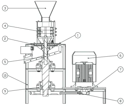
A conventional disc crusher machine has a feed hopper, conduit toward discs, power transmission system and discs. Th e disc crusher that was used for this study has two concentric discs, one fi xed and one rotating; and they are at an adjustable dis-tance. Th e disintegration process in disc crushers begins when the raw materials, in this case sweet corns, are poured into the inlet of the machine, which is usually a hopper. Th en the sweet corns enter a chamber where they are driven to the sur-face of the disc by a screw. Th e crushed corns enter on the discs and disintegration occurs. Th e above description corresponds to the disintegration pro-cess of the particles in the disc crushers used for this analysis. Fig. 1 shows the scheme of the disc crusher machine.
Th e driving force or power needed for crushing certain amount of grain depends on many factors; it depends on the crushing system, layout of ma-chinery components, the type of construction sys-tem, and fi nally the engine system. Th e shortage of lubrication, poor maintenance of machinery, trans-missions, lack of cleanliness, etc., all these factors cause higher power consumption (RiCHardSon 1950).
[image:2.595.311.528.502.686.2]Th e study of disintegration process started as-suming that it is possible to simulate the process following a partially deterministic manner. Th is is
Fig. 1. Disc crusher machine
possible if the intrinsic characteristics of the prod-uct are known and the discs are conditioned to a geometry that fi ts properly. A particle inside the discs has speed and acceleration. Th ese relation-ships give rise to a more complex analysis that in-cludes fi ctitious forces such as centripetal or Co-riolis forces; these forces are not considered since it is a static calculation. Th e trajectory that describes a particle can be a logarithmic spiral (VaCulÍK et al. 2013). Th is conclusion is taken into account for the design of the disc geometry. For a proper ar-rangement of variables involved in the disintegra-tion process, the raw material is characterized as spherical bodies with uniform physical properties that do not depend on its mass.
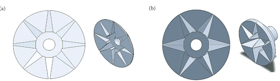
Th e analysis begins proposing suitable geometry. Th e discs are designed considering the movement of the raw material through the channels. With the movement of the mobile disc, the spheres are ac-commodated in the disc channels. As a result, a section of sphere volume protrudes on the mobile disc surface and the fi xed disc cuts it. For this pur-pose, two geometries are studied. Th e dimensions of the discs depend on the initial volume and the fi nal volume of the spherical body. Th e centres of these spherical bodies are contained in a line. Th is
line forms a determined angle with the plane of the disc surface. Th e number of channels of the disc depends on the volume of the fi rst spherical body. Two types of geometries for the mobile disc are de-signed, one square section and the other triangular. In both types, the section is reduced as it approach-es to the external limit of the disc (Fig. 2).
Th e spherical bodies are tangent to the chan-nel walls and between them. Th e accommodation of the spherical bodies within the channel enables to situate, according to their volume, each spheri-cal body in a determinate position. Naturally, the sphere of larger volume is located at the entrance of the channel, i.e. closest to the centre of the disc. Th e sphere of higher volume is obviously located at the fi rst position and the smaller at the last posi-tion, see Fig. 3.
Th e next step is to calculate the number of spherical bodies that can enter the channel, Eq. (1) (AGuedo 1991). Th is amount is verifi able through computational modelling of the disc. Th e 3D mod-elling of the discs in a CAD program allows observ-ing and determinobserv-ing the forces and distributions of the spheres, which are not found in AGuedo’s works (1991):
(1)
(2) where: n– number of spheres that may be within the channel; R1 and Rn – radii of the fi rst and last spheri-cal bodies, respectively; α – angle between the line that joins the centres of the spheres and a horizontal plane (Fig. 4), the angle α is independent of the type of chan-Fig. 2. Disc with (a) eight radial channels of square section, and (b) six radial channels of triangular section
[image:3.595.65.516.87.218.2](a) (b)
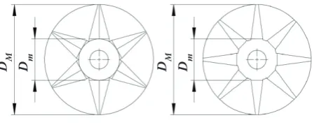
[image:3.595.69.286.604.706.2]nel section; DM, Dm – outer and inner diameters of the mobile disc respectively (Fig. 5)
To establish the direction and magnitude of the forces acting on each spherical body, it is necessary to defi ne two reference systems. Origin of the fi rst refer-ence system coincides with the centre of the mobile disc surface. Th e second reference system xyz is also located on the surface of the mobile disc, but it rotates with the same angular velocity as the mobile disc. Th e second reference system is used to study the position of the spheres through the disc channels.
Th e thrust force FE, which is directed to the centre of each particle, is located on a plane parallel to the
YZ plane. Th e purpose of this force is to push the spherical bodies through each channel (Fig. 6). Th e orientation of this force is independent of the type of disc section. FR is the reaction force resulting from the interaction between spherical bodies. Th e forces FE and FR have opposite directions, but the same magnitude. FR pushes the body toward the centre of the disc (Fig. 6). Th e forces FR and FE are not consid-ered in the work performed by AGuedo (1991).
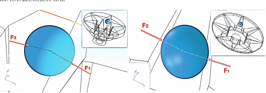
Th e forces F1 and F2are defi ned as the reaction forces on the spheres due to contact with the wall of the channels (Fig. 7), Eq. (3) and Eq. (4) repre-sent the forces F1 and F2 in vectorial form. In addi-tion, modules of these forces are diff erent for each spherical body.
F→1i= (–F1i μ1x, –F1i μ1y, –F1i μ1z) (3) F→2i = (0 , –F2i μ2y, F2i μ2z) (4) where: µ1, µ2 – direction cosines for the forces F→1i and F→2i, respectively; F1i, F2i – modules of F→1i and F→2i
It is worth mentioning that the direction cosines depend on α; details are shown in Appendix A.1.
Th e force Fcis due to the interaction between the spherical body and the fi xed disc. Th is force is re-sponsible for the sphere volume reduction. In addi-tion, it is responsible for the position of the bodies through the disc channel. Finally, Fc depends on the radius, density and shear strength of the spherical body (Fig. 8a).
F→Ci= (τAisin(ei), τAi cos(ei), –τAi ctg(di)) (5)
where: F→Ci – force vector defi ned for each spherical body; τ – shear strength of spherical bodies; Ai– area of the section where the cutting occurs; ei – angle between the direction of the force τAiand an axis parallel to y
axis; di – angle between FC and an axis parallel to z axis (Fig. 7b)
It is worth mentioning that ei and di are diff erent for each spherical body. Th is relationship is valid for both channel sections. C represents the circle that encloses the area A. Fig. 8b shows the com-ponents of the force FC. It is important to mention that the component FCx is not equal to τA. Fgi is the gravity force, which only depends of the volume and density of each spherical body.
[image:4.595.63.288.93.206.2]So far, the forces are obtained in terms of vari-ables that depend on the channel geometry. A sim-ple computer program, which is based in Eq. (6), is coded to obtain numerical results.
Fig. 4. Angle α
[image:4.595.311.533.101.200.2]R1 – radius of the smaller sphere
Fig.5. Geometry discs of triangular section (a) and square section (b)
DM, Dm – outer and inner diameters of the mobile disc respectively
Fig. 6. Representation of the forcesFE and FR for each sphere FE – thrust force; FR – reaction force resulting from the interaction between spherical bodies
D M
D M D m Dm
[image:4.595.66.289.612.703.2]F→E+ F→R+ F→1+ F→2+ F→C+ F→g= 0 (6) From Eq. (6), it is possible to obtain three equa-tions in x, y and zdirections. Each equation is lo-cated in a matrix form according to Eq. (7).
A × X =B (7)
where: where:
where: the values of the matrix A are constant for all the spherical bodies and are defi ned according to the disc geometry, these values are defi ned in Ap-pendix A.2. Th e values of the matrix X correspond to the modules ofF→1, F→2 and F→E. B is a matrix of the known terms.F→C and F→gcan be obtained directly. For the last sphere, the force F→R is zero, and because
of this, it is possible to solve Eq. (7). Th erefore, the forcesF→1,F→2 and F→E can be calculated. So the force F→R for the penultimate sphere is known. Following the proposed logic and with the help of computa-tional calculation, it is possible to solve Eq. (7) for each sphere.
Once forces acting on each sphere are known, it is possible to calculate the power required to move the mobile disc trough the drive shaft. Eq. (8) shows the power consumed in each sphere:
[image:5.595.67.533.79.242.2]Pot =w→× (→ri× F→i) (8) where: w→ – angular velocity vector with which the mobile disc rotates; F→ – applied force on the surface of the mobile disc; →r – the vector from the centre of the mobile disc toward the point of application of forceF→.
[image:5.595.72.504.545.741.2]Fig. 7. Representation of the forces F1 and F2 for a disc radial channel of (a) triangular and (b) square section F1, F2– reaction forces on the spheres due to contact with the wall of the channels
Th e forcesF→1andF→2produce torque. Eq. (8) is ap-plied on each sphere. Th erefore, the total power to be transmitted is the sum of the power calculated in each spherical body, see Eq. (9).
PotTOTAL = ∑niw→× (→r
i × –F→i) (9)
Th e physical and mechanical properties of agri-cultural products are essential for producing suita-ble designs (MÜller et al. 2014). For this paper, the product is sweet corn, its shear strength is 300 kN/ m2, and its density is 600 kg/m3 (those values were
determined experimentally).
RESULTS AND DISCUSSION
To obtain the forces acting on the sphere, it is necessary to know some geometric parameters of the discs, such as DM (160 mm), Dm (60 mm), the radius R1 of the fi rst body (9 mm), radius for the last sphere Rn (2 mm) and angular velocity w
(360 RPM). Using the parameters given in Eq. (1) and Eq. (2), the values of α and n are 8° and 6, re-spectively, this can be verifi ed graphically using the static computational modelling. Applying Eq. (7), the values of FE, F1 and F2 are obtained (Table 1).
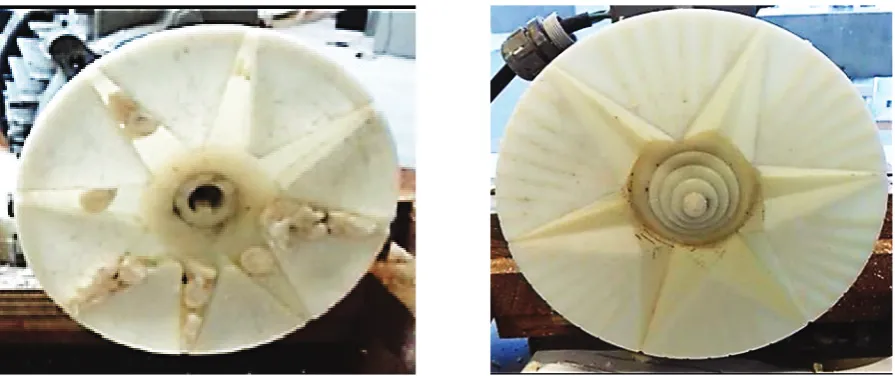
Replacing the forces obtained in Eq. (9), the power consumed in each kind of mobile disc is obtained. In the square section disc, the power is 0.77 HP and in triangular section disc, the power is 1.03 HP. It was noted that it is more appropri-ate to work with a square section disc, because it consumes less power than a triangular section disc. Nevertheless, the thrust force FEin a square sec-tion disc is greater than the thrust force in a trian-gular section disc, as it causes diffi culties to push the raw material through the disc channel, which was experimentally verifi ed (Fig. 9).
[image:6.595.68.534.112.233.2]It is worth mentioning that if it is desired to choose an electric engine, it is necessary to add an extra power; it is due to a loss of power in mecha-nisms that produce the thrust forceFE, and power transmission system.
Table 1. Forces for each sphere positioned within the disc channel
Square section Triangular section
i FE (N) F1 (N) F2(N) FE (N) F1(N) F2(N)
1 24.73 16.02 32.67 11.32 42.26 23.75
2 15.84 11.97 20.47 7.53 27.55 13.73
3 9.55 8.84 12.58 4.72 17.76 7.56
4 5.37 6.45 7.53 2.84 11.28 3.82
5 2.68 4.65 4.32 2.49 6.99 1.62
6 1.005 3.29 2.31 0.86 4.19 0.39
i – accountant; FE – thrust force; F1, F2– forces that produce torque
[image:6.595.72.520.554.742.2]For more reliable results, further studies on dy-namic analysis of disc crushers should be per-formed. However, this static method gives an ac-ceptable estimate of the power consumed in disc crushers, and gives an approximation of the re-quired thrust force to move a raw material through the disc channel. Consequently, further studies need to be carried out in order to improve the pre-sent methodology.
CONCLUSION
The proposed method allows calculating the power consumed by disc crushers in a disintegra-tion process. The factors that determine the con-sumed power are disc geometry and the forces act-ing on it; it is associated with the geometry of the raw material for milling. This methodology aims at simplifying the way to calculate the power in disc crushers and it gives a close estimation of real in-dustrial data; thus it can be used as a preliminary indicator of the power required in disc crushers.
Appendix
A.1. Values of direction cosines of Eqs (3 and 4) Values for a disc channel of square section μ1x = cos(α)
μ1y = cos(α) sin(α) μ1z = 1 – cos(α)2
μ2x = 0
μ2y = 2cos(α) sin(α) μ2z = 1 – 2cos(α)2
Values for a disc channel of triangular section μ1x = μ2x = √3/2cos(α)
μ1y = μ2y = 3/2cos(α) sin(α) μ1z = μ2z = 1 – 3/2cos(α)2
A.2. Values of the elements of matrix A, which belong to Eq. (7) Values for a disc channel of triangular section
k11 = –√3/2cos(α)
k12 = √3/2cos(α)
k13 = 0
k21 = –3/2cos(α) sin(α)
k22 = –3/2cos(α) sin(α)
k23 = 1
k31 = 1 – 3/2cos(α)2
k32 = 3/2cos(α) –1
k33 = 0
Values for a disc channel of square section
k11 = –cos(α)
k12 = 0
k13 = 0
k21 = cos(α) sin(α)
k22 = 2cos(α) sin(α)
k23 = 1
k31 = cos(α)2 – 1
k32 = 2cos(α)2 – 1
k33 = 0
References
Aguedo Villacorta J. (1991): Diseño de un molino de discos de 160 mm. de diámetro para molienda de maíz (Design-ing of a disk mill 160 mm. of diameter for corn mill(Design-ing). Pontificia Universidad Catolica del Perú, Perú.
Feller W. (1968): An Introduction to Probability Theory and Its Applications. Volume I. London-New York-Sydney-Toronto, John Wiley & Sons.
Gennaro A.R. (2003): Remington Farmacia. Vol. 1.
Hibbeler R.C. (2006): Mecánica de materiales (Materials mechanics). Mexico, Pearson educación.
Kim S.M., Dien B.S., Tumbleson M.E., Rausch, K.D., Singh V. (2016): Improvement of sugar yields from corn stover using sequential hot water pretreatment and disk milling. Bioresource Technology, 216: 706–713.
Leone A. (2014): Olive milling and pitting. In: Perri C. (ed.):The Extra-Virgin Olive Oil Handbook. Willey: 117–126. Leone A., Esposto S., Tamborrino A., Romaniello R.,
Tatic-chi A., Urbani S., Servili M. (2016): Using a tubular heat exchanger to improve the conditioning process of the olive paste: Evaluation of yield and olive oil quality. European Journal of Lipid Science and Technology, 118: 308–317. Leone A., Romaniello R., Zagaria R., Sabella E., De Bellis
L., Tamborrino A. (2015): Machining effects of different mechanical crushers on pit particle size and oil drop dis-tribution in olive paste. European Journal of Lipid Science and Technology, 117: 1271–1279.
Müller M., Horníčková Š., Hrabě P., Mařík J. (2015): Analysis of physical, mechanical and chemical properties of seeds and kernels of Jatropha curcas. Research in Agricultural Engineering, 61: 99–105.
Oduntan O.B., Omitoyin, B.O. (2015): Wear of disc mill hammer in wet grinding processes on groundnut cake for fish feed pro-duction. Research in Agricultural Engineering, 61, 162–169. Richardson A. (1950): Tratado de molinería. Barcelona,
Editorial Sintesis.
Tamborrino A., Pati S., Romaniello R., Quinto M., Zagaria R., & Leone A. (2014): Design and implementation of an automatically controlled malaxer pilot plant equipped with an in-line oxygen injection system into the olive paste. Journal of Food Engineering, 141: 1–12.
Vaculík P., Maloun J., Chládek L., Přikryl M. (2013): Disinte-gration process in disc crushers. Research in Agricultural Engineering, 59: 98–104.
Zueva G.A., Padokhin V.A., Ditl P. (2010): Stochastic models of solid particles grinding. Acta Polytechnica, 50 (2). Zuñiga J.M., Mantari J.L. (2017): A computational
methodol-ogy to calculate the required power in disc crushers. Jour-nal of ComputatioJour-nal Design and Engineering, 4: 14–20.