Abstract— Modern technologies provide various types of Distributed Energy Resources (DER), constituted by small size generators and storage systems, such as photovoltaic arrays, fuel cells, those need DC section known as DC Micro grid which is generally a two wire network before interfacing with the ac network. In this paper a new half bridge voltage balancer is implemented which converters two wire system in to three wire system by building a neutral line in the DC network. Unfortunately, the shoot-through problems occurs in the bridge legs of the half bridge voltage balancer which degrades the reliability of the voltage balancer. So, a novel improved Dual-Buck half bridge intelligent voltage balancer with a Fuzzy controller is proposed to eliminate the shoot through problems which proportionally increases the efficiency of the network. The proposed intelligent voltage balancer may have a good ability of balancing the voltage by building a neutral line using fuzzy controller even under the unbalanced loads and transiently changing loads. This topology is implemented in MATLAB/SIMULINK environment and simulation results will be verified.
Index Terms—DC Micro grid, Dual-Buck converter, shoot-through problems, dc distribution system, continuous conduction mode(CCM), discontinuous conduction mode(DCM), half bridge, voltage balancer, Distributed Energy Resources (DER),
I. INTRODUCTION
ith the increasing threat of the fast depletion of resources such as petroleum, coal, and natural gas forces, people seek renewable energy sources, such as solar, wind, geothermal, and hydraulic energies. in recent years, fuel cell (FC) research and development have received special attention for their higher energy-conversion efficiency and lower co2 emissions than thermal engines in the processes of converting fuel into usable energies. In recent years with the development of renewable resource generations. Traditional controllers like PI controllers are also well fit for this type of balancers [1]. MICRO-DC grid based on distributed generation system, which can supply super high-quality electric power, is widely focused [2]–[9]. The use of the direct current allows simplifying the insertion between the distribution generation and the network. It needs only one interface converter with alternating current grid to make the operation in islanding mode easier, without compromising the safety of the public network [10], and it has a distinct benefit—a line loss reduction [11]. A micro-dc grid is also dependent on all types of interfacing converter, such as bidirectional converter and dc converter [12], [13], grid-connected inverter [14]–[16], voltage balancer [2]–[8], and so on.
The advantages of dc micro grids are summarized as follows.
1) The system efficiency becomes higher because of the reduction of conversion losses of inverters between dc output Sources and loads
2) There is no need to consider about synchronization with the utility grid and reactive power.
3) When a blackout or voltage sag occurs in the utility grid, it does not affect the dc bus voltage of dc micro grid directly
Due to the stored energy of the dc capacitor and the voltage control of ac/dc converter. Therefore, DGs in dc system are not easy to trip against these disturbances. In other words, dc micro grid already has fault-ride-through capability of its own. This kind of dc distribution system is suitable for dc output type distributed generations such as photovoltaic and energy storages such as secondary batteries and EDLCs When power failure occurs in commercial grid, the dc micro grid works independently supplying power that is disconnected from the commercial grid. Batteries may be connected with a dc bus via a dc-dc converter to control charge and discharge.
However, a micro-dc grid usually has only one voltage level in two-wire dc distribution system, and it is impossible to supply some types of loads at half voltage such as dc/ac inverters needing a neutral line, converters with input voltage balancing like half-bridge converter and three-level half-bridge converter, and so on. In particular, when a micro-dc grid is used in domestic places, a neutral line connected to ground is favorable to the security of the persons. Obviously, in practice, a micro-dc grid with two-wire power system is impossible to meet the requirements of all electronic devices. Thus, a half-bridge voltage balancer was specially introduced to build a neutral line which can easily convert a two-wire dc grid into a three-wire dc grid by a neutral line. In practice, the voltage balancer may be dispersedly used in any place where the voltage balance is needed, and of course, it can be placed at the output side of the power supply center for building a whole three-wire dc grid. It is thus evident that the voltage balancer improves the quality and flexibility of power supply in a micro dc grid. But the topology of bridge-type converters maybe suffers from shoot-through risk at some fault conditions, even with added dead time, shoot-through is still the reason for dominant failure of the circuit, which is a major drawback to the reliability of this type of power converters.
The dual-buck half-bridge converter typically consists of two legs with one operating at the positive half-cycle while the other one working at the negative half-cycle. The dual-buck type inverters do not need dead time, and they totally eliminate the shoot-through concerns, thus leading to greatly enhanced system reliability. It can be hard switched because the body diode of MOSFET never conducts, and the external diodes can be independently selected to minimize switching losses. The freewheeling current goes through the independent freewheeling diodes instead of the body diode of the
G. S. N. M. VENKATESH,
M. Tech,Asst. Prof., & KIRANKUMAR PATURU,
M. Tech, Asst. Prof.,
Department of Electrical and Electronics Engineering,
Raghu Institute of Technology, Vishakapatnam
Smart & versatile Voltage Balancer in DC Micro
Grid with Fuzzy Controller
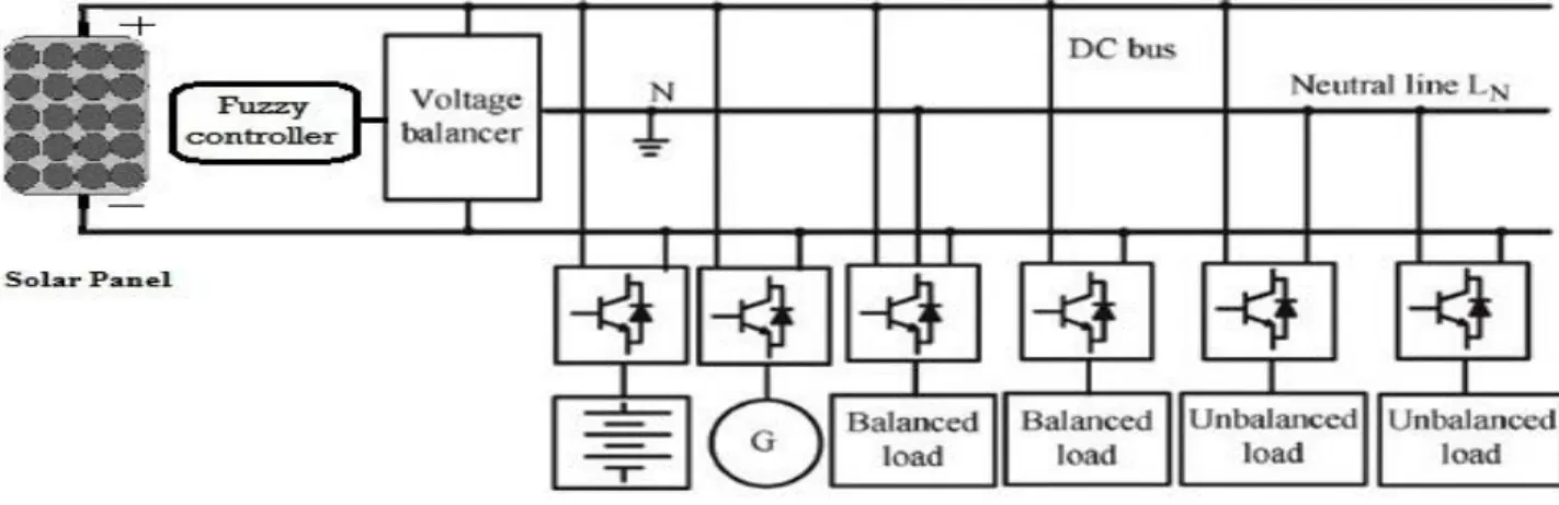
Fig.1. Typical structure of a micro-dc grid with various loads
switches, and all the switches and diodes are operated at half of the line cycle; thus the efficiency may be improved [17]–[22].
In recent years, the number and variety of applications of fuzzy logic have increased significantly. The applications range to industrial process control, medical instrumentation, decision-support systems, and portfolio selection.
. Fuzzy logic has two different meanings. In a narrow sense, fuzzy logic is a logical system, which is an extension of multivalve logic. However, in a wider sense fuzzy logic (FL) is almost synonymous with the theory of fuzzy sets, a theory which relates to classes of objects with unsharp boundaries in which membership is a matter of degree. In this perspective, fuzzy logic in its narrow sense is a branch of fl. Even in its more narrow definition, fuzzy logic differs both in concept and substance from traditional multivalve logical systems.
. The basic concept in FL, which plays a central role in most of its applications, is that of a fuzzy if-then rule or, simply, fuzzy rule. Although rule-based systems have a long history of use in Artificial Intelligence (AI), what is missing in such systems is a mechanism for dealing with fuzzy consequents and fuzzy antecedents. In fuzzy logic, this mechanism is provided by the calculus of fuzzy rules. The calculus of fuzzy rules serves as a basis for what might be called the Fuzzy Dependency and Command Language (FDCL). Although FDCL is not used explicitly in the toolbox, it is effectively one of its principal constituents. In most of the applications of fuzzy logic, a fuzzy logic solution is, in reality, a translation of a human solution into FDCL.
In this paper, a dual-buck half-bridge voltage balancer is proposed. A Fuzzy control strategy is implemented for driving the two left and right bridge legs of the voltage balancer to work for a high efficiency. In order to select the parameters of filter inductors and capacitors and to design the control system parameters, the relationships of the currents of inductors, the capacitors, and the unbalanced loads are described in detail, and the small-signal model is derived.
Finally, a prototype, which may deal with 3-kW power unbalance ability, is implemented in the MATLAB environment to verify that the dual-buck half-bridge voltage balancer may have a good ability of balancing the voltages of the 3 wire system by building a neutral line.
II. MODELING OF SOLAR PANEL
The typical equation governing the PV arrays is given by below algorithm
Fig.2. Pv panel model
Solar cells naturally exhibit a nonlinear I-V and P-V
characteristics which vary with the solar irradiation
and cell temperature. The typical I-V and P-V
characteristics of solar cell are shown in figure 3.
Fig. 3. Characteristics of solar cell
The fundamental parameters related to solar cell are short circuit current (Isc), open circuit voltage (Voc), maximum power point (MPP), efficiency of solar cell and fill factor. Solar panels on the offshore are connected parallel to wind energy dc collection cables
III. TOPOLOGY AND CONTROL STRATEGY OF THE PROPOSED INTELLIGENT VOLTAGE BALANCER
i. Typical structure of a micro-dc grid with various loads DC micro grid is an appropriate system to interconnect kinds of dc output sources and to supply high quality power A typical structure of a micro-dc grid [1]–[7] with an intelligent voltage balancer is shown in Fig. 1, in which a neutral line is built by using a voltage balancer achieving two same voltage levels for requirements of different types of loads, such as unbalanced loads, half-bridge converter and inverter, and so on.
ii. Proposed intelligent voltage balancer
The proposed voltage balancer—a dual-buck half-bridge voltage balancer—is shown in Fig. 4, which is made up of a left bridge leg (S1,D1, L1), a right bridge leg (S2,D2, L2),and a neutral line LN usually connected to the earth ground. If the conventional driving technology is adopted between the switches S1 and S2, the two-inductor currents iL1 and iL2 will always exist during a switching period, and the unbalanced load current value (iRLoad2 − iRLoad1) is equal to the different value between the current average value iL1 and iL2.
Fig.4. Proposed dual buck half bridge voltage balancer
Thus, the two inductor currents will cause additional power losses which leads to system inefficiency. It is very essential to have a control strategy that can drive the left bridge leg and the right bridge leg, respectively, based on the different power quantity of the balanced and unbalanced loads. Hence voltage balancer is placed near a converter to balance positive and negative voltages. It is also possible to place it near load side.
iii. Proposed control strategy with fuzzy controller
The proposed control strategy is presented in Fig. 5. The output signal ue of the fuzzy controller directly sent to control the switch S1, and its negative value (−ue) controls the switch S2. Combining Figs. 4 and 5, it may be concluded that, when RLoad2 is lower than RLoad1, the signal ue is +ve and the left bridge leg will be driven while the right bridge leg will not work, and on the contrary, the signal ue is -ve and the right bridge leg will be driven. So in the proposed technique only one of the two bridge legs will work during every switching period and the loss of the other bridge leg will be avoided compared with the traditional driving strategy.
Fig.5. Proposed control strategy with fuzzy controller
IV. PRINCIPLE OF OPERATION BASED ON THE PROPOSED CONTROL TECHNIQUE
Same as traditional buck converter, each leg of the bridge operates in 2 modes namely continuous conduction mode (CCM) and discontinuous mode operation (DCM). For simplifying the analysis of the operational principle, some assumptions are made:
1) All inductors and capacitors are ideal, C1 = C2 = C, and L2 =L2 = L;
2) The output voltages uout1 and uout2 are not changed during each switching process; and
3) All power switches and diodes are the ideal devices with ignored switching time and conduction voltage drop. As the operating procedures of the right bridge leg are the same as those of the left bridge leg, only the analyzing procedure of the left bridge leg is given in the paper. The function of output capacitor is to filter the inductor current ripple and deliver a stable output voltage.
i. CCM OF LEFT BRIDGE LEG
Fig.6. Gating signal and inductor current in CCM mode
The driving signal ugs1, the current iL1, and the equivalent circuits are shown in Figs. 6, during CCM. From Fig. 6, there are only two main operating modes during each switching period. Mode 1: [t0, t1] [Refer to Figs. 6 ]:The switch S1 is turned on at
the time t0, and the current iL1 increases linearly The input current which rises flows through filter inductor L1, filter capacitor C1, and load resistor.
(1)
During this mode, the input voltage uin sends additional energy to the load RLoad2 through the inductor L1. The input voltage uin is the voltage stress of the freewheeling diode D1
Mode 2: [t1, t2] [Refer to Figs. 6]: The switch S1 is turned off at the time t1, and the current iL1 will continue to run through the freewheeling diode D1. The current iL1 decreases linearly
(2)
Fig.7. Equivalent circuits under CCM.(a)Mode 1, (b)Mode 2
The procedure will end when the S1 is turned on again at the time t2. During this mode, the voltage stress of the switch S1is also the input voltage uin.
The freewheeling diode D1 conducts due to energy stored in the inductor, and the inductor current continuous to flow through L1,C2, load and diode D1. The inductor current falls until switch S1 on again in next cycle. Depending on switching frequency filter inductance and capacitance, the inductor current could be discontinuous. The time (t1-t0 ) is equal to the time (t2-t1) , i.e. the turn on time is equal to the turn off time.
From the time t2, a next operating period will start.
As the voltage uout1 is the same as uout2 under the stabilization and a voltage-second product of an inductor is zero during a period, it can be concluded
(3) Thus, the time (t1 − t0) is equal to the time (t2 − t1), i.e., the turn-on time is equal to the turnoff time because both the capacitors are in charging mode.
ii. DCM OF LEFT BRIDGE LEG
Fig.8. Equivalent circuits under DCM Mode 3
Fig.9. Gating signal and inductor current under DCM
There are three operating modes under DCM. The ugs1, iL1, and equal circuits are shown in Figs. 9. From Fig. 9, it can be concluded that the mode 1 [t0, t1] and the mode 2 [t1, t2] are in accordance with the two mode sunder CCM, respectively. Therefore, only the mode 3 [t2, t3] is given. Mode 3 [t2, t3] [Refer to Figs. 9: During this time interval [t2, t3] ,the loads RLoad1 and RLoad2 are supplied by the voltage sources Uout1 and Uout2 because energy stored in inductor is zero. The energy stored in the capacitor is discharged to the load. According to the voltage-second product of an inductor, it is got from Fig. 8.
(4) Thus, the time (t1 − t0) is equal to the time (t2 − t1); this means that the turn-on time (t1 − t0) is smaller than the turnoff time (t3 − t1) as shown in figure because there should be definitely a DCM between switching.
V. FUZZY LOGIC CONTROLLER
The word Fuzzy means vagueness. Fuzziness occurs when the boundary of piece of information is not clear-cut. In 1965 Lotfi A. Zahed propounded the fuzzy set theory. Fuzzy set theory exhibits immense potential for effective solving of the uncertainty in the problem. Fuzzy set theory is an excellent mathematical tool to handle the uncertainty arising due to vagueness. Understanding human speech and recognizing handwritten characters are some common instances where fuzziness manifests.
Fuzzy set theory is an extension of classical set theory where elements have varying degrees of membership. Fuzzy logic uses the whole interval between 0 and 1 to describe human reasoning. In FLC the input variables are mapped by sets of membership functions and these are called as ―FUZZY SETS‖.
Fuzzy set comprises from a membership function which could be defines by parameters. The value between 0 and 1 reveals a degree of membership to the fuzzy set. The process of converting the crisp input to a fuzzy value is called as ―fuzzificaton.‖ The output of the Fuzzier module is interfaced with the rules. The basic operation of FLC is constructed from fuzzy control rules utilizing the values of fuzzy sets in general for the error and the change of error and control action. Basic fuzzy module is shown in fig.10.
The results are combined to give a crisp output controlling the output variable and this process is called as ―DEFUZZIFICATION.‖
Fig.10. Fuzzy Basic Module i. Fuzzy Rules
COE
E
NB NM NS
ZE
PS
PM PB
NB
NB NB NB NB NM NS ZE
NM
NB NB NB NM NS
ZE
PS
NS
NB NM NS NS
ZE
PS PM
ZE
NB NM NS
ZE
PB
NS ZE
PS
NM NS
ZE
PS
PM PM PB
PM
NS
ZE
PS PM
PB
PB PB
PB
ZE
PS
PM PB
PB
PB PB
In the fuzzy control, input and output variables are the size of the form to describe in words, so to select special vocabulary to describe these variables, generally used in "big, medium and small" Three words to express the controller input and output variables state, plus the positive and negative directions, and zero, a total of seven words : { negative big, negative medium, negative small, zero, positive small, middle, CT } , the general terms used in the English abbreviation prefix : {NB , NM, NS , ZE, PS , PM, PB}.
ii. Membership function plots
A membership function (MF) is a curve that defines how each point in the input space is mapped to a membership value (or degree of membership) between 0 and 1. A membership function for a fuzzy
set A on the universe of discourse X is defined as µA: X → [0,1], where each element of X is mapped to a value between 0 and 1. This value, called membership value or degree of membership, quantifies the grade of membership of the element in X to the fuzzy set A. Membership functions allow us to graphically represent a fuzzy set. The x axis represents the universe of discourse, whereas the y axis represents the degrees of membership in the [0,1] interval. Simple functions are used to build membership functions. Because we are defining fuzzy concepts, using more complex functions does not add more precision. Below is a list of the membership functions we will use in the practical section of this tutorial. Triangular function: defined by a lower limit a, an upper limit b, and a value m, where a < m < b.
Fig.11. Input 1
Fig.12. Input 2
Fig.13. Output
Membership functions plots, Fig.11, Fig.12, Fig 13 are the input 1, input2 and output of fuzzy controller respectively. These plots are obtained according to the rules written in the fuzzy tool box and the switching process depends upon these rules. Figure 14 shows the Simulink implementation of fuzzy controller
Fig.14. Simulink model of fuzzy controller.
VI. SIMULATION RESULTS
The proposed topology is successfully implemented in MATLAB/SIMULINK environment and simulation results are analyzed by simulations of the main current relationships and the transient load changing. Considering the dc bus voltage i.e., the solar panel output (input voltage uin) is selected to be
Fig.15. Simulation results of the current relation under left bridge leg-CCM
I. Simulations of the Current Relationships
Simulation results of the current relationships of the left bridge leg are given. The simulation results of the current
relationships are given in Fig. 15, 16. In Fig. 15, it includes CCM [RLoad1 = 100 Ω and RLoad2 = 10 Ω and DCM [RLoad1 = 40 Ω and RLoad2 = 30 Ω as shown in Fig. 16. As seen from Fig. 15, 16 under nonzero iL1, it can be easily Concluded that Δuout1 = −Δuout2, iC1 = iC2, and ΔiL1 = iC2 − iC1.
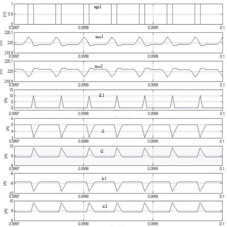
Fig.16. Simulation results of the current relation under left bridge leg-DCM When the inductor current iL1 is zero, we can get Pout1 = u2 out1/RLoad1 = 1080 W, Pout2 = u2 out2/RLoad2 = 2200 W, iin = (Pout1 + Pout2)/uin = 7.45 A, i2 = i1 = iin = 7.45 A,
iRLoad1 = uout1/RLoad1 = 6 A, and iRLoad2 = uout2/RLoad2 = 10 A under steady state. Because of i2 < iRLoad2, the lacking current (i2 − iRLoad2 = −0.75 A = iC2) is supplied by the capacitor C2 discharging, and the voltage uout2 linearly drops. Due to i1 > iRLoad1, the capacitor C1 is charged by the surplus current (i1 − iRLoad1 = 1.45 A = iC1), and the voltage uout1 linearly rises. These states are presented in Fig. 16.s
II. Simulations of Loads Instantly Changing
Fig. 17, 18 shows the simulation results of loads transiently changing, where Fig. 17 gives the results of the load current the load current iRLoad1 changes from 0 to 8 A; Fig. 18 describes the results of iRLoad2 changes from 0 to 6 A. As seen from Fig. 17, 18, the left bridge leg will operate when iRLoad2 is larger than iRLoad1; otherwise, the right bridge leg will run. At the same time, the output voltages uout1 and uout2 are nearly equal, although they have obvious fluctuations when the loads are instantly changed. The fluctuations are mainly caused by a longer regulated time of the voltage regulator whose output signal polarity is altered under transiently changing loads as seen from Fig. 5.
Fig.17. Simulation results under Rload1 load transiently changing.
VII. CONCLUSION
The proposed topology is implemented successfully with a dual-buck half-bridge voltage balancer and its Fuzzy control strategy is simulated. This type of voltage balancer can overcome shoot-through problems. It can build a neutral line to balance two output voltages for different loads in a micro-dc grid. By analyzing the results we can illustrate the proposed voltage balancer have good ability of balancing output voltage even if under the different input voltage, unbalanced loads, and transiently changing loads.
REFERENCES
[1]. Xianjin Zhang and Chunying Gong, ―Dual-Buck Half-Bridge Voltage Balancer‖, IEEE Trans. Industrial Electronics, vol. 60, no. 8, pp. 3157-3164, Aug 2013.
[2]. H. Kakigano, Y. Miura, T. Ise, and R. Uchida, ―DC voltage control of the dc micro-grid for super high quality distribution,‖ in Proc. IEEE Power Electron. Spec. Conf., Jeju, Korea, 2006, pp. 518–525.
[3]. H. Kakigano, Y. Miura, T. Ise, and R. Uchida, ―DC voltage control of the dc micro-grid for super high quality distribution,‖ in Proc. IEEE Power Electron. Spec. Conf., Jeju, Korea, 2006, pp. 518–525.
[4]. H. Kakigano, Y. Miura, T. Ise, and R. Uchida, ―DC micro-grid for super high quality distribution—System configuration and control of distributed generations and energy storage devices,‖ in Proc. Power Electron. Spec.Conf., 2006, pp. 1–7.
[5]. M. Brenna, E. Tironi, and G. Ubezio, ―Proposal of a local dc distribution network with distributed energy resources,‖ in Proc. 11th Int. Conf.Harmon. Quality Power, 2004, pp. 397–402.
[6]. H. Kakigano, Y. Miura, and T. Ise, ―Low-voltage bipolar-type dc micro grid for super high quality distribution,‖ IEEE Trans. Power Electron.,vol. 25, no. 12, pp. 3066–3075, Dec. 2010.
[7]. J. Lago, J. Moia, and M. L. Heldwein, ―Evaluation of power converters to implement bipolar dc active distribution networks—DC–DC converters,‖in Proc. Energy Convers. Congr.Expo., 2011, pp. 985–990. [8]. H. Kakigano, A. Nishino, and .Ise, Distribution voltage control for dc
with fuzzy control and gain-scheduling control,‖inProc. Int.Conf. Power Electron., 2011, pp. 256–263.
[9]. T. Tanaka, T. Sekiya, Y. Baba, M. Okamoto, and E. Hiraki, ―Anew half-bridge based inverter with the reduced-capacity dc capacitorsfor dc micro-grid,‖ in Proc. Energy Convers. Congr.Expo., 2010,pp. 2564– 2566.
[10]. H. Kanchev, D. Lu, F. Colas, V. Lazarov, and B. Francois, ―Energy management and operational planning of a micro grid with a PV-based . active generator for smart grid applications,‖ IEEE Trans. Ind. Electron., vol. 58,no. 10, pp. 4583–4592, Oct. 2011
[11]. 1547TM IEEE Standard for Interconnection Distributed Resources With Electric Power Systems, IEEE Standard Coordinating Committee 21.
[12]. P. Chiradeja, ―Benefit of distributed generation: A line loss reduction analysis,‖ in Proc. Transmiss&Distrib. Conf. Exhib., Asia–Pac., 2005,pp. 1–5.
[13]. L. S. Yang and T. J. Liang, ―Analysis and implementation of a novel bidirectional dc–dc converter,‖ IEEE Trans. Ind. Electron., vol. 59, no. 1,pp. 422–434, Jan. 2012.
[14]. S. V. G. Oliveira and I. Barbi, ―A three-phase step-up dc–dc converter witha three-phase high-frequency transformer for dc renewable power source applications,‖ IEEE Trans. Ind. Electron., vol. 58, no. 8, pp. 3567–3580,Aug. 2011.
[15]. Y.Wang, Q. Gao, and X. Cai, ―Mixed PWM for dead-time elimination andc ompensation in a grid-tied inverter,‖ IEEE Trans. Ind. Electron., vol. 58,no. 10, pp. 4797–4803,Oct. 2011.
[16]. J. M. Espí, J. Castelló, R. Garc´a-Gil, G. Garcerá, and
E. Figueres, ―An adaptive robust predictive current control for three-phasegrid-connected inverters,‖ IEEE Trans. Ind. Electron., vol. 58, no. 8,pp. 3537–3546, Aug. 2011.
[17]. N. A. Rahim, K. Chaniago, and J. Selvaraj, ―Single-phase seven-level grid-connected inverter for photovoltaic system,‖ IEEE Trans. Ind. Electron.,vol. 58, no. 6, pp. 2435–2443, Jun. 2011.
[18]. J. Liu and Y. G. Yan, ―Novel current mode controlled bi-buck half-bridge,‖J. Nanjing Univ. Aeronaut.Astronaut., vol. 25, no. 20, pp. 122– 126,Mar. 2003.
[19]. C. H. Zhu and Y. G. Yan, ―A novel series/parallel output dual buck inverter,‖ Proc. China Soc. Elect. Eng., vol. 25, no. 20, pp. 12–15, Oct.2005.
[20]. H. X. Ma, C. Y. Gong, and Y. G. Yan, ―Output filter design of half-bridge dual-buck inverter using hysteresis current controller,‖ Proc. China. Soc.Elect. Eng., vol. 27, no. 13, pp. 98–103, Jul. 2007.
[21]. H. Z. Wang, Z. Q. Cai, J. Liu, and Y. G. Yan, ―A novel three level dual buck half-bridge inverter,‖ Trans. China Electron. Soc., vol. 24, no. 2,pp. 73–77, Feb. 2009.
[22]. Z. L. Yao, L. Xiao, and Y. G. Yan, ―Dual-buck full-bridge inverter with hysteresis current control,‖ IEEE Trans. Ind. Electron., vol. 56, no. 8,pp. 3153–3160, Aug. 2009.
[23]. H. F. Xiao and S. J. Xie, ―Transformerless split-inductor neutral point clamped three-level PV grid-connected inverter,‖ IEEE Trans. Power Electron., vol. 27, no. 4, pp. 1799–1808, Apr. 2012.
AUTHOR’S PROFILE
G. S. N. M. VENKATESH,
Received M.Tech with specialization in Advanced Power systems from J.N.T.University, Kakinada, East Godavari (Dt), Andhra Pradesh, India. He is currently working as an Assistant professor at Raghu Institute of Technology, dhakamarri, Visakhapatnam, A.P. His areas of interest are Power Systems, Power Electronics & Industrial drives.
KIRANKUMAR PATURU
,Received M.Tech with specialization in Energy Engineering from J.N.T.University, Hyderabad, Andhra Pradesh, India. He is currently working as an Assistant professor at Raghu Institute of Technology, dhakamarri, Visakhapatnam. His areas of interest are Electric machines, Renewable energy sources and Power electronics