Speed Control of Oscillation Free IM Drive Using Adaptive-Fuzzy Sliding
Mode Control
S. Anusha
1, P. Preethi
2, M. Anka rao
3 1PG Scholar, Dept. Of Electrical & Electronics Engineering, JNTUACEA, Anantapuramu, A.P., India 2
PG Scholar, Dept. Of Electrical & Electronics Engineering, JNTUACEA, Anantapuramu, A.P., India 3
Asst.Professor, Dept. Of Electrical & Electronics Engineering, JNTUACEA, Anantapuramu, A.P., India
---***---ABSTRACT- In order to get the high frequency oscillation
free induction motor drive based on the boundary layer approach for speed control of an indirect field-oriented control (IFOC)of an induction motor(IM) drive. The boundary layer approach leads to a tradeoff between control performances and oscillations elimination. In indirect vector control of IM flux and torque are decoupled under estimation of the slip speed with appropriate information of the rotor time constant. To improve the control performances a system is assigned as reaching control part of the fuzzy sliding mode so that under the large uncertainties it eliminates the high frequency oscillations completely. The applied fuzzy controller acts like a saturation function with a nonlinear slope in side thin boundary layer near the sliding surface to guarantee the stability of the system. In this paper the simulation results show the effectiveness of proposed adaptive fuzzy sliding mode control of induction motor drive at different operating conditions.
INDE740X TERMS: Indirect Field-oriented control (IFOC), Siding mode control (SMC) Fuzzy sliding mode control (FSMC),Induction motor (IM).
I. INTRODUCTION
SMC based system are more features like it offers more dynamic response and more stable control system, it requires easy software/hardware implementation. Due to discontinuous nature, it has some limitations for electric drives, shows the high frequency oscillations as chattering characters. These characters make various undesirable effects such as current harmonics and torque pulsation. In recent years, the chattering issue has become the research focus of many scholars. Generally, introducing a thin boundary layer around the sliding surface can solve the oscillations problem by interpolating a continuous function inside the boundary layer of switching surface. However, the slope of the continuous function is a compromise between control performance and high frequency oscillation elimination. Also, asymptotic stability is not guaranteed and may cause a steady-state error. To tackle these problems, a fuzzy approach has been considered as a potential candidate to handle uncertainty in plant dynamic over the past three decades.
The high frequency oscillation issue has become the research focus of many scholars in recent years. By
introducing a thin boundary layer around the sliding surface can solve the oscillation issue by interpolating a continuous function inside the boundary layer of switching surface. However, the slope of the continuous function is a compromise between control performance and oscillation elimination. And also, asymptotic stability is not guaranteed and may cause a steady-state error. To overcome these problems, a fuzzy approach has been developed as a potential candidate to handle uncertainty in plant dynamic over the past three decades. Advantages of fuzzy theory to handle nonlinear uncertainties are well-known In this paper, the fuzzy approach is applied to cope with the saturation function in reaching control part of the control effort in the SMC system. The salient advantages of the designed fuzzy controller on the basis of the SMC system are decreasing the number of fuzzy rules and relaxation of the uncertainty bound requirement. The proper design of the fuzzy controllers can eliminate the chattering phenomenon and improve the tracking performance with small uncertainty in nonlinear system. However, the IM drive frequently faces the large uncertainties including external load disturbance and parameters variations. Therefore, in this paper a fuzzy sliding-mode control (FSMC) technique is developed for IM drive to handle the large uncertainties.
Adaptive fuzzy sliding-mode position controllers for Adaptive fuzzy sliding mode position controllers for an IFOC of IM drive were investigated. However, the singleton fuzzifier was used for output fuzzy sets, which is not sufficient to cover all operating conditions. Moreover, the authors in these works did not test the performance of IM drive against step changes of position, speed, and load, which frequently encounter in practice. An SMC control technique was reported in. However, the SMC was not free from oscillations in torque responses due to the lack in proper development of control algorithm. Thus, the developed SMC is not acceptable for high performance drives. In this paper, the saturation function in reaching control part is replaced by the proper design of fuzzy controller to guarantee the stability of the system so that the switching control law acts like saturation function technique with a nonlinear slope inside the thin boundary layer near sliding surface. The applied fuzzy controller improves the tracking performance despite the system uncertainties while the high frequency oscillation is reduced significantly.
155
A fuzzy sliding mode speed controller with a load torque
observer was designed for a permanent magnet synchronous motor (PMSM) drive. But, the structure of the FSMC was not adapted online to cope with uncertainties and minimize the control effort. To overcome the disadvantages of the existing system an adaptive fuzzy based speed controller is developed for induction motor drive in this paper. Induction motors are used worldwide as the work-horse in most of the industrial applications. Such motors are widespread because they are robust, easily installed, controlled and adaptable for many processes. Indeed, in the industrialized countries, approximately 70% of the entire electrical power available is consumed by AC drives, whereas most of them are IMs. Induction motors play a vital role in the industrial sector, especially in the field of electric drives and control without proper control of speed, it is virtually impossible to achieve the desired task for a specific application. General-purpose applications of induction motors include control of pumps, conveyors, machine tools, centrifugal machines, presses, elevators and packaging equipments. On the other hand, applications in hazardous locations include control of petrochemical and natural gas plants, whereas severe environment applications for induction motors include the control of grain elevators, shredders and equipment for coal plants. Advantages of IM over other electric machines includes the structural simplicity, robustness, ruggedness, durability, reliability, low cost, low weight and inertia, less failure rates and virtually maintenance-free electrical drives. IMs do not require any type of connection between the stator and the rotor. Unlike that of the DC motors, IM does not require any commutator brushes, which make it a very good entity to be used in explosive situations as sparks are not produced. Thus, these machines could be categorized as maintenance-free machines and cost-effective. The above-mentioned advantages show the superiority of the usage of IM over other types of electrical motors in various industrial applications. Hence, it becomes a perfect rotational energy conversion machine for variable speed application Induction motor drives find numerous applications in modern-day automation. Speed control in industrial drives can serve several purposes. The variable frequency drive or variable speed drive can control the RPM of a motor, which drives a fan, pump, conveyor belt or other machine. In our work, we concentrate on the speed control of IMs using some sophisticated control techniques. The advantage of using speed controllers for speed control of electric drives is that, the speed of the machine can be matched to the set value and if deviated from the set value due to any disturbances, it can be automatically brought back to the set value using feedback loops in the designed controller.
The advancements in power electronics and PWM technique during the last three decades wrapped up the modern control of motor drives. Over the last fifteen years, major improvements in motor drive stability and efficiency were made. This was due to significant progress in all relevant fields, as follows: The invention of highly efficient and fully
controllable power semiconductor switches such as, MOSFET, SCR, IGBT, etc. The new topologies such as four-leg, resonant and soft-switching converters. The invention of new AC machine control strategies such as FOC theory and SVPM techniques. Optimized control solutions and their analysis, such as PID, hysteresis, adaptive and FLC strategies, ANN, genetic algorithms and hybrid control, etc. A variable voltage is required because the motor impedance reduces at low frequencies and consequently the current has to be limited by reducing the supply voltages. Hence, considerable research could be done in this area. The aim was to find even simpler methods of speed control of IMs. Historically, number of controllers has been developed by various researchers. To name a few of the controllers developed by them include the scalar, vector, field acceleration and hybrid controllers. Invention of vector control technique, the induction motor became popular for variable speed drives. In indirect vector control of induction motor flux, torque are decoupled under estimation of the slip speed with information of rotor time constant. The accuracy of motor parameters particularly rotor time constant plays important role in indirect vector control. In this project indirect field oriented control is used. Indirect Field Oriented Control (IFOC) is known to produce high performance in induction Motor (IM) drives by decoupling rotor flux and torque producing current components of stator current. The decoupling control between the rotor flux and the torque is no longer achieved in terms of stator current components this paper introduces a decoupled rotor flux and torque control based on the magnetizing current components by incorporating PI control system and using space vector modulation (SVM) technique. It is able to perform high performance control in IM drives using SVM technique. In order to perform the control strategy, the rotor flux and magnetizing current estimator is proposed. A good performance is obtained By means of PI controller and SVM technique, and the rotor flux and the magnetizing current are obtained properly by the proposed observer. Induction machines are largely used in industrial plants and are adequate for almost any kind of environment. Their popularity is due to their high efficiency, reliability, low maintenance.
The sliding mode control has a unique place in control theories. First, the exact mathematical treatment represents numerous interesting challenges for the mathematicians. Secondly, in many cases it can be relatively easy to apply without a deeper understanding of its strong mathematical background and is therefore widely used in engineering practice. This article is intended to constitute a bridge between the exact mathematical description and the engineering applications. After a short overview of the sliding mode control the article presents its mathematical foundations, namely the theory of differential equations with discontinuous right-hand sides. The power electronic circuits, which always have some kind of switching elements, can be typically described by such differential equation. Such equations don’t fulfill the regular theorem of existence and uniqueness, but under certain conditions remain valid, if we interpret the
solution of the differential equation according to the definition proposed by Filippov. The article presents a practical example of the definition proposed by Filippov per a sliding mode control of an L-C circuit and an experimental application on uninterruptible power supply.
II. DYNAMIC EQUATIONS OF IM
The mathematical models of an IM in synchronously rotating reference axis are shown in
Te= ( - ) (1)
In IFOC, the rotor flux is oriented entirely in d-axis setting rotor flux 0,
= (2) The slip frequency is obtained as
= ( ) (3) The electromagnetic developed torque is given by
Te = = Kt (4)
Where
Kt= (5)
The mechanical equation of an induction motor can be presented as follows:
Jr r(t)+B r(t)=Te-TL ( 6)
Where B, jr and TL are represented as friction factor, rotor
inertia and the external load disturbance, respectively. Substituting (4) and (5) in (6) yields
r(t) = - r(t)+ - = Bp r+ Ap + DpTL(7)
To achieve the nominal model of IM drive, nominal value of the parameters must be considered without any disturbances. Thus the nominal model of the IM drive given by (8) can be written as
r(t) = r+ (8)
To handle the uncertainties, they must be considered and added to the nominal model for real-time induction motor(IM) drive. So, the dynamic (9) considering structured and unstructured uncertainties and un modeled dynamics for the actual IM drive is obtained as
r(t) = ( + ∆B) r(t) + ( +∆A) + DpTL + δ (9)
= r(t) + + L(t)
Where L(t) = ∆ B r(t) ++∆A +DpTL + δ .
In the above equation, the uncertainties are shown by ∆A and
∆B. In addition, unstructured uncertainty due to detuning
field-orientation in the transient state and the un-modeled dynamics in practical applications are shown as δ. In the above equation, L(t)is called lumped uncertainty and is assumed that the bound of L(t)is unknown but it is limited as L(t) is greater than m where, m is positive constant.
Parks transformation
The 3-phase machine can be represented by an equivalent two phase machine. He replaced the variables (v, i) associated with the stator windings of machine with variables associated with fictitious windings rotating with the rotor at synchronous speed. Essentially he transformed or referred stator variables to a synchronously rotating reference frame fixed in the rotor. This reference is referred as rotor reference frame. With this transformation, the time varying inductances that occur due to an electric circuit in relative motion and electric circuits with varying magnetic reluctances can be eliminated.
The above relation relating to the three phase axes and d-q axes variables are called parks transformation. In the late 1930 H.C.stanely showed that the time varying inductances in the voltage equations of an induction machine due to electric circuits in relative motion could be eliminated by transforming the variables associated with the rotor windings to variables associated with fictitious stationary windings. In this case, rotor variables are transformed to frame of reference frame fixed in the stator referred as stator reference frame or stationary reference frame or Stanley reference frame. G.Kron introduced a change of viable which eliminated the time varying inductances of a symmetrical induction machine by transforming both stator variables and rotor variables to a reference fame rotating in synchronism with the rotating magnetic field. This frame referred as synchronously rotating reference frame. Thus all known real transformation used in an induction machine analysis are contained in one general transformation which eliminates all time varying inductances by referring the stator and rotor variables to a frame of reference which may rotate at any angular velocity or remain stationary. Then all known real transformation may then be obtained by simply assigning the appropriate speed of rotation to this so called arbitrary reference frame
.
s greater than m where, m is positive constant.Reference Frame Theory
The time varying coefficients in matrix obtained after applying the phase transformation can be avoided by applying
157
a second transformation. This transforms the quantities of stator and rotor to a common reference frame. In the voltage equations, which describe the performance of the electrical machines, it is found that some of the machine inductances are functions of the rotor speed. Thus coefficients of voltage equations are time varying. A change of variables is often used to reduce the complexity of these differential equations. In the late 1920 R.H park transformed all stator variables to a frame of reference fixed in the rotor.
Fixed axis to rotating axis
Similarly
Linear Transformation
The term linear transformation means that the transformation form old to new set of variables or vice versa is governed by linear equations.These equations have the following general form
[New variables] = [Transformation matrix] [old variables] or [Old variables] = [Transformation matrix] [New variables] Thus the transformation matrix is defined as a matrix containing the coefficients relating the old and new variables. Normally the transformation used in the AC machine analysis converts the actual three phase to two phase machine and additional zero sequence system. I.e. phase transformation. The physical basis for the development of thistransformation is the equivalence of mmf and invariance of power.
III. PI-BASED SLIDING MODE CONTROL
The PI controller (proportional integral controller) is a feedback controller. It drives the plant which is to be controlled with a weighted sum of error and the integral of that value. Figure1. Basic block of PI Controller. The sliding mode controller is not suitable for large uncertainties because
output is a discontinuous high frequency switching signal due to these problem proportional integral sliding mode controllers is used.
Advantages and disadvantages: (1) PI controller increases
the order and the type of the system by one. It also causes the steady state error to reduce to the zero, which is not the case for proportional only control in general. (2) PI controller improves damping and reduces maximum overshoot. It also decreases the bandwidth and improves the rise time.
The conventional SMC suffers from chattering in both speed and current. Thus, the harmonic losses of the motor with the proposed AFSMC will be less as compared to the conventional PI SMC. It is also found that the speed tracking error is almost zero for the proposed AFSMC controller despite parameters variation and a continuous command speed change. An adaptive fuzzy sliding-mode controller based IFOC of IM drive has been presented in this paper.
Fig.1 Block diagram of PI controller
Field-Oriented control is the most popular method of obtaining improved or high performance in an induction motor drive. There are two basic categories of field oriented control: the direct and the indirect method. The main difference between them is that the direct method accomplishes commutation with electrical or magnetic feedback from the motor while the indirect method accomplishes commutation with velocity feedback from the motor and a feed forward slip command. Both schemes typically utilize some type of stator current regulation. The indirect field-orientation method utilizes the motor velocity feedback and a feed forward slip command to provide the instantaneous commutation.The PI controller requires precise linear mathematical models, which are difficult to obtain and may not give satisfactory performance under parameter variations, load disturbances, etc. Recently, Fuzzy Logic Controllers (FLCs) have been introduced in various applications and have been used in the power electronics field. The advantages of fuzzy logic controllers over conventional PI controllers are that they do not need an accurate mathematical model, Can work with imprecise inputs and Can handle non-linearities and are more robust than conventional PI controllers
IV.ADAPTIVE FUZZY SLIDING MODE CONTROL
The block diagram of sliding mode controller consists of adaptive fuzzy sliding mode controller is shown in fig:2 the AFSMC is used as a speed controller which gives the command torque component of the stator current as output. The oscillations phenomenon can be eliminated by smoothing out the control discontinuity in a thin boundary layer near the sliding surface. In fact, sign function is replaced by sat function which is defined as follows:
sat( ) = , if |S| ≤ | Ψ | (10) = sgn(S) otherwise
Where Ψ is defined as the boundary layer thickness. Then, the reaching control part is changed as
μr(t) = – ( h) -1
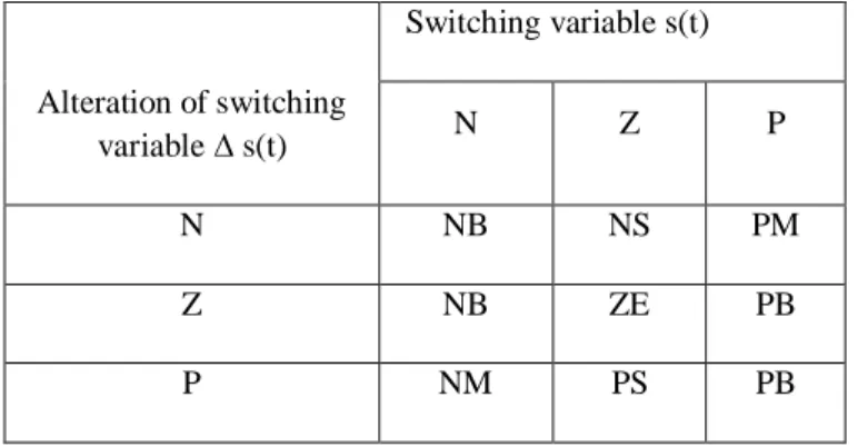
k(t) sat (S(t)) (11) By applying the above reaching control, the control performance may not be suitable as the high frequency oscillations still exists with large uncertainties. To tackle these problems, the saturation function is replaced by the fuzzy system which acts like a saturation function with a nonlinear slope inside the thin boundary layer. Triangular type input membership functions (MFs) with fuzzy sets negative (N), zero (Z), and positive (P) and output MFs with fuzzy sets negative big (NB), negative medium (NM), negative small (NS), zero (ZE), positive small (PS), positive medium (PM), positive big (PB) on the common interval [−1 1] are used for the proposed FSMC. According to these the thickness of the boundary layer can be changed by varying the range of the fuzzy sets “Z” and “ZE” in the input and output. Since the fuzzy system structure is based on the saturation function technique, the best thickness of the boundary layer can be derived from a fixed boundary layer SMC, which selects the saturation function as reaching control part. Thus, the boundary layer thickness can be adjusted in two steps as follows
Step 1) Varying the slope of a saturation function so that the best performance is achieved for the fixed boundary
layer sliding-mode based speed controller. Step 2) Varying the range of the fuzzy sets “Z” and “ZE” to settle the selected value of boundary layer in the first step for the proposed FSMC-based speed controller.
According to these the value of the boundary layer thickness (ψ)is obtained as 0.75 in this project. The fuzzy rules with 9 rules and Mamdani type fuzzy inferring method are designed to have an appropriate tracking response, fast dynamic speed response, eliminate chattering phenomenon and satisfy the requirement of stability condition. An SMC control technique was reported in however, the SMC was not free from chattering in torque responses due to the lack in proper development of control algorithm. Thus, the developed
PI sliding mode controller is not acceptable for high performance drives. An adaptive fuzzy sliding mode speed controller with a load torque observer was designed for a permanent magnet synchronous motor (PMSM) drive .But, the structure of the FSMC was not adapted online to cope with uncertainties and minimize the control effort. To overcome the disadvantages of the aforementioned FSMC, a adaptive fuzzy based sliding mode controller is developed for induction motor drive in this paper.
Fig.2 Block diagram of AFSMC-based IM drive The fuzzy system can be represented as, μfsmc = FSM (S(t),∆S(t) (12)
Then the reaching control part and control effort can be defined as
μr(t) = – ( h)-1 k(t) μfsmc (13)
μ(t) = μeq(t) – ( h)-1 k(t) μfsmc (14)
Triangular type input membership functions (MFs) with fuzzy sets negative (N), zero (Z), and positive (P) and output MFs with fuzzy sets negative big (NB), negative medium (NM), negative small (NS), zero (ZE), positive small (PS), positive medium (PM), positive big (PB) on the common interval [−1 1] are used for the proposed FSMC. According to these the thickness of the boundary layer can be changed by varying the range of the fuzzy sets “Z” and “ZE” in the input and output. Since the fuzzy system structure is based on the saturation function technique, the best thickness of the boundary layer can be derived from a fixed boundary layer SMC, which selects the saturation function as reaching control part. Thus, the boundary layer thickness can be adjusted in two steps as follows.
Step 1) Varying the slope of a saturation function so that the best performance is achieved for the fixed boundary layer sliding-mode based speed controller
Step 2) Varying the range of the fuzzy sets “Z” and “ZE” to settle the selected value of boundary layer in the first step for the proposed FSMC-based speed controller. In this paper, we came across the designing of induction motor using both PI controller and fuzzy logic controller. We also come across PI controller introduction, characteristics and fuzzy logic controller’s introduction, its operations, membership functions
159
and its configurations
Table 1: Membership function Input membership function
Output membership function
V.
Simulation results
The performance of the proposed AFSMC –base IM drive has been investigated in MATLAB. To show the superiority the performance of the AFSMC is compared with PI controllers. The tuned PI controllers with anti-windup correction term are used as d-q axis current controller are initially tuned by the Ziegler-Nichols method based on stability boundary. The saturation of the controller is avoided by adding a correction of the integral term KC. In terms of
overshoot and settling time, the AFSMC controller exhibits the best performance among all controllers with step changes
in command speeds. These approaches are referred to as fuzzy sliding-mode controls (FSMC). The conventional SMC suffers from chattering in both speed and current. Thus, the harmonic losses of the motor with the proposed AFSMC will be less as compared to the conventional SMC. It is also found that the speed tracking error is almost zero for the proposed AFSMC controller despite parameters variation and a continuous command speed change
.
Fig 3(a) Simulation result of PI controller-based IM drive for speed
Fig 3(b) Simulation result of PI controller-based IM drive for current
Fig 4(a) Simulation result of AFSMC controller-based IM drive for speed
Switching variable s(t) Alteration of switching variable ∆ s(t) N Z P N NB NS PM Z NB ZE PB P NM PS PB
Fig 4(b) Simulation result of AFSMC controller-based IM drive for current
S NO
PI Controller AFSMC Controller
1. From the above fig no 3(a) it can be observe that the oscillations are still exist between 5A-10A.
By observing the above figures it can be observe that there is no oscillations in current.
2. By using PI Controllers the high frequency oscillations are still exist in both current and speed.
By using the AFSMC Controller it can be seen that there is no oscillations in both current and speed.
Table 2:Comparison between PI and AFSMC Controllers By observing the above graphs the tuned PI controller sliding mode based IM drive still suffers with high frequency oscillations while the adaptive fuzzy sliding mode controller obtained oscillations free induction motor drive.
VI. CONCLUSION
An indirect field oriented control of IM drive for Adaptive fuzzy sliding mode control has been presented in this paper. The controller for the structure of proposed system is based on the smoothing out the discontinuity of control in a thin boundary layer near the sliding surface. In order to guarantee the asymptotic convergence of the speed tracking error and improve the control system performance, adaptive - fuzzy system is compensated using a robust term in control law. The adaptive-fuzzy controller acts like saturation function technique with a non linear slope inside the thin boundary layer because the fuzzy system based on the fixed boundary layer. The proposed controller was found superior to the PI Controller and conventional sliding mode controller at different operating conditions such as step change in command speed, load disturbance, and parameter variations. The proposed adaptive fuzzy system reduced the steady-state oscillations in current and ensures less harmonic loss and heat dissipation in the motor. In this paper, fuzzy approach is applied with saturation function in reaching control part of the control effort in SMC system. Fuzzy control (FC) possesses several advantages such as robustness, being model free, universal approximation theorem, and rule-based algorithm. However, the huge amount of fuzzy rules required for a high-order system makes the analysis complex. To resolve this, researchers have proposed the fuzzy control design methods based on the sliding-mode control scheme. These approaches are referred to as fuzzy sliding-mode controls (FSMC). The conventional SMC suffers from chattering in both speed and current. Thus, the harmonic losses of the motor with the
proposed AFSMC will be less as compared to the conventional SMC. It is also found that the speed tracking error is almost zero for the proposed AFSMC controller despite parameters variation and a continuous command speed change.
REFERENCES
[1] J. A. Santisteban and R. M. Stephan, “Vector control methods for induction machines: An overview,” IEEE
Trans. Educ., vol. 44, no. 2, pp. 170–175, May 2001.
[2] K. Wang, J. Chiasson, M. Bodson, and L. M. Tolbert, “An online rotor time constant estimator for the induction machine,” IEEE Trans. Control Syst. Technol.,
vol. 15, no. 2, pp. 339–348, Mar. 2007.
[3] L. Faa-Jeng, C. Po-Huan, C. Chin-Sheng, and L. Yu-Sheng, “DSP-based cross-coupled synchronous control for dual linear motors via intelligent complementary slidingmode control,” IEEE Trans. Ind. Electron., vol.
59, no. 2, pp. 1061–1073, Feb. 2012.
[4] S. M. Gadoue, D. Giaouris, and J. W. Finch, “MRAS sensorless vector control of an induction motor using new sliding-mode and fuzzy-logic adaptation mechanisms,” IEEE Trans. Energy Convers., vol. 25, no.
2, pp. 394–402, Jun. 2010.
[5] Y. Zhao, W. Qiao, and L. Wu„ “An adaptive quasi-sliding-mode rotor position observer-based sensorless control for interior permanent magnet synchronous machines,” IEEE Trans. Power Electron., vol. 28, no.
12, pp. 5618–5629, Dec. 2013.
[6] C. Lin, T. Liu, M. Wei, L. Fu, and C. Hsiao, “Design and implementation of a chattering-free non-linear sliding-mode controller for interior permanent magnet synchronous drive systems,” IET Elect. Power Appl.,
vol. 6, no. 6, pp. 332–344, Jul. 2012.
[7] F. Barrero, A. Gonzalez, A. Torralba, E. Galvan, and L. G. Franquelo, “Speed control of induction motors using a novel fuzzy sliding-mode structure,” IEEE
Trans. Fuzzy Syst., vol. 10, no. 3, pp. 375–383, Jun. 2002.
[8] Z. Jinhui, S. Peng, and X. Yuanqing, “Robust adaptive sliding-mode control for fuzzy systems with mismatched uncertainties,” IEEE Trans. Fuzzy Syst., vol.
18, no. 4, pp. 700–711, Aug. 2010.
[9] T. Orowska-Kowalska, M. Kaminski, and K. Szabat, “Implementation of a sliding-mode controller with an integral function and fuzzy gain value for the electrical
161
drive with an elastic joint,” IEEE Trans. Ind. Electron., vol. 57, no. 4, pp. 1309–1317, Apr. 2010.
[10] R. Pupadubsin et al., “Adaptive integral
sliding-mode position control of a coupled-phase linear variable
reluctance motor for high-precision applications,” IEEE
Trans. Ind. Appl., vol. 48, no. 4, pp. 1353–1363,
Jul./Aug. 2012.
[11] A. J. Garrido, I. Garrido, M. Amundarain, M. Alberdi, and M. De la Sen, “Sliding-mode control of wave power generation plants,” IEEE Trans. Ind. Appl.,
vol. 48, no. 6, pp. 2372–2381, Nov./Dec. 2012.
[12] R. Lorenz, “A simplified approach to continuous on-line tuning of fieldoriented induction machine drives,” IEEE Trans. Ind. Appl., vol. 26, no. 3, pp. 420– 424, May/Jun. 2002.
[13] F. Cupertino, D. Naso, E. Mininno, and B.
Turchiano, “Sliding-mode control with double boundary layer for robust compensation of payload mass and friction in linear motors,” IEEE Trans. Ind. Appl., vol.
45, no. 5, pp. 1688–1696, Sep./Oct. 2009.
[14] Y. K. Kim and G. J. Jeon, “Error reduction of sliding mode control using sigmoid-type nonlinear interpolation in the boundary layer,” Int. j. control syst., vol. 2, no. 4, pp. 523-529, 2004.
[15] C.-J. Chien, “A combined adaptive law for fuzzy iterative learning control of nonlinear systems with varying control tasks ,” IEEE Trans.Fuzzy Syst., vol. 16, no. 1, pp. 40-51 , Feb. 2008.