1
Optimization Water Leakage Detection using Wireless
Sensor Networks (OWLD)
Motaz Daadoo Department of Computer Systems Engineering, Palestine Technical University - Kadoorie
(PTUK), Tulkarm, Palestine. [email protected]
Amna Eleyan Department of Computing School of Computing, Mathematics &
Digital Technology
Manchester Metropolitan University Manchester-UK
Derar Eleyan
Department of Computer Systems Engineering, Palestine Technical
University - Kadoorie (PTUK), Tulkarm, Palestine. Birzeit University, Department of
Computer Science [email protected]
ABSTRACT
This paper presents a technical method to monitor the water distribution pipelines against leakage and to control the pump when the water level decreases in the tank. Water leakage is the most popular cause of water wasted in the domestic water distribution systems. Nowadays most people have their smartphone nearby them; therefore, adding an interface on the smartphone to control an automated system is a big plus. Energy saving is a benefit of the Optimization Water Leakage Detection (OWLD) system. It enables us to save energy, time and cost by having smart leakage detection in pipelines, measuring the water level in the tank and controlling the pump when the water level is low. This paper focuses mainly on two parts: The first part is an alarm based on Global System for Mobile technology (GSM) to send a Short Message Service (SMS) to the owner. This is made up of the following components: sensors, GSM Module, Arduino and relays to control the device. The second is the controlling part; it uses android application mobile to control the pump. The proposed system can effectively improve the efficiency of operation, reduce delay time and cost of maintenance pipelines after leakage detection.
Keywords
GSM Technology, Optimization Water Leakage Detection (OWLD), Wireless Sensor Networks (WSN)
1.
INTRODUCTION
Many people do not realize the real importance of drinking enough water every day. More water is wasted by many uncontrolled ways. This problem is quietly related to poor water allocation, inefficient use, and lack of adequate and integrated water management. Therefore, efficient use and water monitoring are a potential constraint for home or office water management system. Every living thing on earth needs water to survive. Human bodies are made up of more than 60 % water. We use clean water to drink, grow crops for food, operate factories, and for swimming, surfing, fishing and sailing. Water is vitally important to every aspect of our lives. Monitoring the quality of surface water will help protect our waterways from pollution. Farmers can use the information to help
better manage their land and crops [1]. Our local, state and national governments use monitoring information to help control pollution, water leakage and losses levels.
Depending on the system, which we will produce in this paper, we want to explain some of the difficulties in locating leaks. There are many studies that tells us about the difficulties which interrupt when looking for the water leakage which occurred in the plumbing distribution units and hoses. Some of these difficulties are described below:
First, sources of interference, a variety of common environmental conditions can interference the acoustic method of leak detection, variation in soil properties, moisture, water table and water pressure, locating leaks requires trained and experienced operators and can be problematic in noisy or geologically complex areas. Second, access to test points, which deal with the distance between a detector and the leak, may not be optimal in many cases. Third, pipe location: location of pipe may be difficult in older networks, existing records may be incomplete and of limited use. The last point depends on Plastic pipes, leaks are difficult to determine in segments containing plastic pipes, and plastics dampen vibrations so noise caused by leaks or breaks does not propagate as far as metal pipes.
Benefits of leak detection and repair the faults in the pipelines, water savings, energy savings (treatment and pumping), reduced salary costs and outage times, consumer complaints and improved public relations and reduced property damage and the risk of contamination.
The main reason for leakage of the distribution water pipelines is the pressure on the pipelines when exceeds the maximum pressure rated by the manufacturer when these pipelines designed. Therefore, it will cause a deformation on the pipes and this will lead the pipes to explode during the water flowing through them [2]. After this occurs and the pipes explode, the water will leave its main track and will leave pipes and leakage will occur [3].
In this paper, we will show the whole system ideas, procedure, benefits, devices and apparatus used to accomplish the whole system in a technical way with high efficiency. The main objectives
2 of the proposed system are to detect the leaks in the water pipelines and to control the water level in the tank.
By using the prototype water monitoring system OWLD, we avoid the water wastage, power consumption and easily preserve the water for our generation. In addition, the proposed system will reduce the maintenance costs once leaks are detected in water distribution pipelines at an earlier stage. In our system, we make a home model to be a prototype for OWLD system. The prototype system contains water pipelines with water sensors on points, which have a high probability of water leakage. A microcontroller also required (Arduino) to control and process the actuators on its output ports, also to receive data from water sensors. The Arduino connect to GSM to detect the water leakage and decreasing in water level rapidly and remotely and then send SMS to the owner. In addition, we use the Android application to receive these data from GSM and control on the pump.
2.
Related Work and Our Contribution
Several research efforts have been made in the area of water pipeline leakage monitoring system using Wireless Sensor Network. Almazyad et al. [4] present a scalable design and simulation of a water pipeline leakage monitoring system using Radio Frequency IDentification (RFID) and WSN technology. A group of mobile sensor nodes are deployed in the system. These nodes are either active or sleeping mode. Three techniques are used to wake up the sleeping nodes: location-based, time-based and interrupt-driven. Mathematical models are deployed for each technique to estimate the corresponding energy consumption and memory size requirements. Karray et al. [5] propose a testbed prototype of water pipeline monitoring. A leak detection Predictive Kalman Filter (LPKF) algorithm is proposed for continuous leak detection and localisation for long distance pipes.
Different methods are proposed in Wireless Sensor Networks (WSN) and can be applied on monitoring water pipeline systems. Hammoudeh et al. [5] deploy Linear Wireless Sensor Network (LWSN) for border monitoring and surveillance. In [5], a cross layer routing protocol Levels Division Graph (LDG) is proposed to address the link reliability and the communication needs for LWSN applications such as border monitoring or water pipeline monitoring. In [6], the mapping service is deployed for maximising a distributed information extraction and visualisation from large-scale wireless sensor networks. This mapping service can be applied for monitoring and diagnosing WSN applications such as surveillance systems and water pipeline monitoring systems.
This paper proposes a prototype water monitoring system OWLD. A Wireless Sensor Network (WSN) that helps to monitor the location of water leakage with the help of information sensed by the sensors located above water hoses. This is used to keep the water resource within a standard described for domestic usage and to be able to take necessary actions to restore the health of the degraded water quantity. We use Arduino mega2560 microcontroller to design and build a water leakage detection & a wireless control system, which provides the user with new features such as water leakage detection and water level control in the tank the mobile application. The purpose of the proposed system is to bring comfort and energy saving to our lives.
3.
GSM TECHNOLOGY OVERVIEW
GSM is a globally accepted standard for digital cellular communication. GSM is the name of a standardization group established in 1982 to create a common European mobile telephone standard that would formulate specifications for a pan-European mobile cellular radio system operating at 900MHz. It is estimated that many countries outside of Europe will join the GSM partnership.
The need for people and businesses to be accessible at all times and outside the offices prompted the idea of manufacturing mobile telephones, which use radio waves as the communication medium. The idea was to provide the user with those facilities normally attributed to ‘wire-line’ networks, i.e. place and receive calls to/from other users connected either to fixed or mobile networks. Several cellular systems have existed, the very first ones using analogue technology [4], [5].
A GSM modem is a specialized type of modem, which accepts a SIM card, and operates over a subscription to a mobile operator, just like a mobile phone. GSM uses a process called circuit switching.
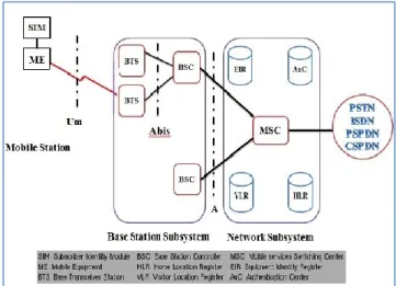
A GSM network is composed of several functional entities, whose functions and interfaces are specified. Figure 1 shows the layout of a generic GSM network. The GSM network can be divided into three broad parts. The Mobile Station (MS) is carried by the subscriber. The Base Station Subsystem (BSS) controls the radio link with the MS. The network Subsystem, the main part of which is the Mobile services Switching Center (MSC), performs the switching of calls between the mobile users, and between mobile and fixed network users. The MSC also handles the mobility management operations. The MS and the BSS communicate across the Um interface, also known as the air interface or radio link. The BSS communicates with the MSC across the A interface [6], [7].
Figure 1. General architecture of a GSM network
3.1
Mobile Station
The Mobile Station ‘MS’ consists of the mobile equipment (the terminal) and a smart card called the Subscriber Identity Module (SIM). The SIM provides personal mobility, so that the user can have access to subscribed services irrespective of a specific terminal. By inserting the SIM card into another GSM terminal, the user is able to receive calls at that terminal, make calls from that terminal, and receive other subscribed services.
3 The mobile equipment is uniquely identified by the International Mobile Equipment Identity (IMEI) [12]. The SIM card contains the International Mobile Subscriber Identity (IMSI) used to identify the subscriber to the system, a secret key for authentication, and other information. The IMEI and the IMSI are independent, thereby allowing personal mobility. The SIM card may be protected against unauthorized use by a password or personal identity number.
3.2
Base Station Subsystem
The BSS is composed of two parts, the Base Transceiver Station (BTS) and the Base Station Controller (BSC). These communicate across the standardized Abis interface, allowing (as in the rest of the system) operation between components made by different suppliers.
The BTS houses the radio transceivers that define a cell and handles the radio-link protocols with the MS. In a large urban area, there will potentially be a large number of BTSs deployed, thus the requirements for a BTS are ruggedness, reliability, portability, and minimum cost.
The BSC manages the radio resources for one or more BTSs. It handles radio-channel setup, frequency hopping, and handovers. The BSC is the connection between the mobile station and the MSC.
3.3
Network Subsystem
The central component of the Network Subsystem (NS) is the MSC. It acts like a normal switching node of the PSTN or ISDN, and additionally provides all the functionality needed to handle a mobile subscriber, such as registration, authentication, location updating, handovers, and call routing to a roaming subscriber [13], [14]. The MSC provides the connection to the fixed networks (such as the PSTN or ISDN). Signaling between functional entities in the NS uses Signaling System Number 7 (SS7), used for trunk signaling in ISDN and widely used in current public networks. The Home Location Register (HLR) and Visitor Location Register (VLR), together with the MSC, provide the call-routing and roaming capabilities of GSM. The HLR contains all the administrative information of each subscriber registered in the corresponding GSM network, along with the current location of the mobile. The location of the mobile is typically in the form of the signaling address of the VLR associated with the MS. There is logically one HLR per GSM network, although it may be implemented as a distributed database. The VLR contains selected administrative information from the HLR, necessary for call control and provision of the subscribed services, for each mobile currently located in the geographical area controlled by the VLR. The geographical area controlled by the MSC corresponds to that controlled by the VLR. Note that the MSC contains no information about particular MS this information is stored in the location registers.
The other two registers are used for authentication and security purposes. The Equipment Identity Register (EIR) is a database that contains a list of all valid mobile equipment on the network, where each mobile station is identified by its IMEI. An IMEI is marked as invalid if it has been reported stolen or is not type approved. The Authentication Center (AuC) is a protected database that stores a copy of the secret key stored in each subscriber's SIM card, which is used for authentication and encryption over the radio channel.
4.
THE OPTIMIZATION WATER
LEAKAGE DETECTION (OWLD) SYSTEM
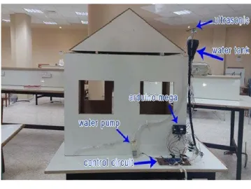
This paper produces a system for detecting the water leakage and control water pump, which is related to a domestic use and needs. This system is applied on a model of a simple home to show and explain how this system can be applicable to be built in of any civil structure. The main purpose of this paper is to describe the structure that we built of our system. We use a home model to build the plumbing network in, also to provide this network with the control parts and the sensors that we used to detect the water leakage and the water level in the upper tank. In addition, the water supply distribution pipes and collector as shown in Figure 2, illustrates the architecture design of the structure model. Figure 2 shows the main parts of the control board, the microcontroller (Arduino), water pump (actuator) and the GSM and their connections.Figure 2. Model of OWLD system
All actuators which, are solenoid valve and the water pump, are activating by a DC voltage with fixed value of 12 volt. A water pump is used to supply the water tank when the water level decreased, this will be happened when the owner of the home use the Android mobile application to turn on the pump depending on the alarm notification alarm of the water level in the upper tank.
5.
HARDWARE DESIGN
Hardware of the system contains water sensors, Arduino mega2560 microcontroller, SIMCOM SIM 900 (GSM module), as shown in Figure 3. This system block diagram defines all the function to be performed by the system. A modular approach to system design was taken. The system is designed based on an Adriano mega2560 microcontroller, which is based on ATmega2560 microprocessor. In this paper, some of the basic concepts of circuits that are used in the system design are explained.
Based on the design requirements and specifications, the first main function of this system is to detect water leakage, which occurs in the distribution units and tracks of the domestic plumbing network. This will be experimentally true and produce acceptable results that will be using water leakage sensors, which will be classified in the hardware components specification. These sensors will be fixed and located mechanically in a true way on the distribution water hoses above the hoses and around the elbows that used to change the direction of the flowing water hoses, the mechanical distribution as shown in Figure 4.
Water leakage sensors distributed mechanically with a sequence related to the solenoid valves. In other meaning, when one of the
4 water leakage sensors detect the leakage and send a signal to the controller, the solenoid valve which is related and supplies the water track which this sensor located on, this valve will close and stop water flow through it.
Figure 3. Functional block diagram of the OWLD
Figure 4. Water leakage sensors and their mechanical distribution
The second main function of this system idea is to detect and measure the water level of the upper domestic tank, which is usually located on the roof. An ultrasonic sensor is used to measure the water height in the tank, depending on the comparison between the actual value of water level and the preselected value. An actuator, which is water pump, will be turned on to supply the upper tank. This actuation of the pump will be wireless control feature using an Android application to control the activation of the pump. As shown in Figure 2, the pump is connected to the upper tank and the ultrasonic is located above the upper level of the water tank. Figure 5 illustrates the main functions of our system, which deals mainly with water leakage and the controlled pump far away using the mobile, and GSM technology. Figure 5 demonstrates theoretically, what happened actually to the system depending on the controller and the control features from the user of the Android application. In addition, all parameters, which are used in the system, are shown Figure 5 and how these parameters are related together.
Figure 5. General-purpose scheme of OWLD system
The system contains water sensors to detect leakage and ultrasonic sensor to measure water level in the tank. The sensors collect information and the system is controlled by the mega Arduino, the controller decides the risk and sends SMS to the owner using a GSM module, according to the sensors information.
The system also consists of two parts: the first is the alarm, if there is one of the risks, the system sends SMS using GSM; it also decreases the risk by opening the water solenoid valves in case of leakage. The second part is controlling using Android application. The application controls the pump and turns on if there is low water level in tank.
Tank water level monitoring is used to avoid overflowing and under flowing level of water in the tank. Water controlling system implementation makes the potential significance in home applications. The existing automated method of level detection is described and that can be used to make a device on/off. Moreover, the common method of level control for the home appliance is simply to start the feed pump at a low level and allow it to run until a higher water level is reached in the water tank. This is not properly supported for an adequate controlling system. Besides this, liquid level control systems are widely used for monitoring of liquid levels, reservoirs, silos, and dams etc.
We have mentioned the hardware components as shown in Figure 3. In this paper, we will go through the system hardware setup systematically in details for combining the components with each other to establish the desired tools and making the connection between the hardware parts with the software commands to get automation sensing unit and actuators. Hardware part of the system nearly was simple and easy to understand and deal with, it contains the controller which is Arduino mega category #2560, water leakage sensors, solenoid valves, ultrasonic sensor, water pump, electrical relays to control the activation of the valves and the pump depending on the input data from sensors and we use ULN 2003 to connect the output pins of the controller with the electrical relays. The following sections describe all hardware components and its specifications and classifications.
5.1
Arduino mega2560 Microcontroller
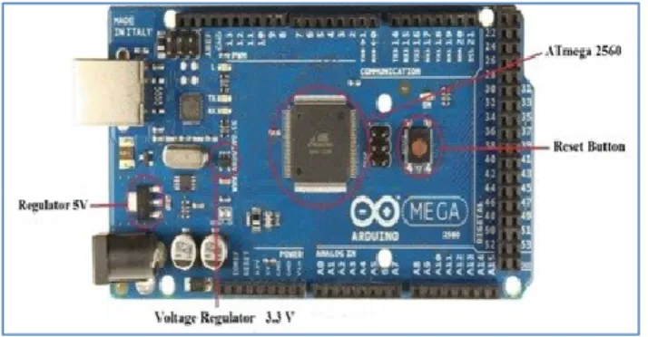
This paper is using an Arduino mega2560 (Figure 6), which is based on an ATmega2560 microprocessor. An Arduino mega2560 microcontroller has been designed based on an ATmega2560 microprocessor that runs at the speed of 16MHz. As Table 1 shows, it contains 54 digital input/output pins, 15 of them could be used as Pulse Width Modulation (PWM), which is a method for getting5 analog results with digital means outputs. Furthermore, it contains 16 analog inputs and 4 hardware serial ports.
Figure 6. Arduino mega2560
Table 1. Specifications of Arduino mega2560 microprocessor
Specifications Arduino mega2560
Processor ATmega 2560
Flash Memory 256 KB
Data Memory 8 KB
EEPROM 4 KB
Digital I/O Pins 54
PWM outputs 15
Analog outputs 16
Clock Speed 16 MHz
Serial Ports 4
5.2
Arduino mega2560 Components
The Arduino controller is a computer-based tool that can considerably sense and control the physical world more than a desktop computer can. Arduino is an open source physical computing platform based on a simple microcontroller board and a development environment for writing software for the board. Arduino mega2560 is a microcontroller board based on the ATmega2560. It has 54 digital I/O pins and 16 analog inputs, any of which could be used either for input or output as shown in Figure 7. They all work at 5 volts and each of them is able to provide/receive a maximum 40mA. Moreover, they have an inner pull-up resistor 20 to 50kΩ. This microcontroller has 16 analog inputs. There is a reset button on the board to reset the microprocessor. In addition, it has a test LED, a USB compatible connection port, a 9V power jack including an ICSP header, which is In-Circuit Serial Programming header. Mega2560 supports I²C (Inter-Integrated Circuit) communication.
Figure 7. Components of an Arduino mega2560
5.3
GSM Module Unit
The GSM modem unit is built using SIMCOM SIM900 modem that specialized for Arduino controller and support GPS technology as shown in Figure 8. This unit can send SMS to user mobile phone and can receive SMS from user.
Figure 8. SIM900 for Arduino controller
The working of GSM modem is based on commands, the commands always start with AT (means ATtention) and finish with a <CR> character. The AT commands are given to the GSM modem with the help of PC or controller. The GSM modem is serially interfaced with the controller with the help of MAX232. Here MAX232 acts as driver, which converts TTL levels to the RS-232 levels. For serial interface GSM modem requires the signal based on RS-232 levels. The T1_OUT and R1_IN pin of MAX232 is connected to the TX and RX pin of GSM modem. The AT commands for GSM-GPRS support is as follows in Table 2:
Table 2. AT commands for GSM-GPRS
• +CMTI : SMS has been received • +CREG: Network registration indication • +CMGS : To send the message
• +CMSS : To Send Message from Storage
• +CMGW: command writes an SMS to the first location available
• +CPMS: command allows the message storage area to be selected (for reading, writing, etc.)
• +CMGR : Read Message • +CCLK : Clock Management
6 Since many GSM network operators have roaming agreements with foreign operators, users can often continue to use their mobile phones when they travel to other countries. SIM cards (Subscriber Identity Module) -holding home network access configurations- may be switched to those will metered local access, significantly reducing roaming costs while experiencing no reductions in service.
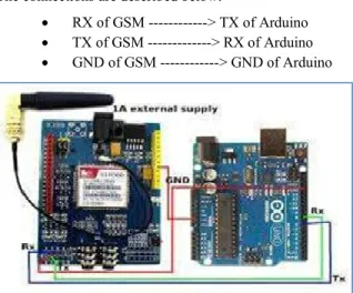
Figure 9 illustrates the GSM 900 connections with Arduino mega. The connections are described below:
RX of GSM ---> TX of Arduino TX of GSM ---> RX of Arduino GND of GSM ---> GND of Arduino
Figure 9. Connect the GSM 900 with Arduino mega
5.4
Water Sensor
Water sensor brick is designed for water detection, which can be widely used in sensing the rainfall, water level, even the liquate leakage. The brick is mainly comprised of three parts: an electronic brick connector, a ‘1’ MΩ resistor, and several lines of bare conducting wires.
This sensor works by having a series of exposed traces connected to ground and interlaced between the grounded traces are the sense traces. The sensor traces have a weak pull-up resistor of 1 MΩ. The resistor will pull the sensor trace value high until a drop of water shorts the sensor trace to the grounded trace. This circuit will work with the digital I/O pins of your Arduino or you can use it with the analog pins to detect the amount of water-induced contact between the grounded and sensor traces.
This item can judge the water level through with a series of exposed parallel wires stitch to measure the water droplet/water size. The item can easily change the water size to analog signal, and output analog value can directly be used in the program function, then to achieve the function of water level alarm. The item has low power consumption, and high sensitivity, which are the biggest characteristics of this module. The item can be compatible with Arduino UNO, Arduino mega2560, Arduino ADK etc. The following Figure shows the physical representation of water sensor.
Figure 10. Physical representation of water sensor
5.5
Ultrasonic Sensor
In this system, we deal with ultrasonic sensor, which main function is to measure simultaneously the level of water in the domestic water tank, depending on the result of the ultrasonic level sensor, we can control in the electrical pump by using the Android application. Figure 11 shows the physical representation of ultrasonic sensor.
Figure 11. Physical representation of ultrasonic sensor
5.6
Water Pump
High pressure micro diaphragm water pump, automatic switch 3.6L/min, DC 12V, 45W, this is a high quality DC micro diaphragm pump, widely used in general industry equipment, farming, tour vehicles, special vehicle, ship, beverage, vehicle cleaning, carpet cleaning, ground cleaning, water purification and water treatment equipment [3].
Figure 12. Control circuit of the water pump
Figure 12 illustrates the control circuit of the water pump and Table 3 shows the specification of water pump.
Table 3. Water pump features
• Working temperature: 0℃ ~ 60 ℃.
• Multi-purpose: can be widely used for garden sprinklers, shower, water taps in the boat, caravan or motor.
• Agricultural purposes: spray for farm chemical, pesticide.
• Corrosion resistant. • Automatic switch.
• Rubber bracket can absorb vibration from the pump. • Working Voltage: 12V DC.
• Current Range: 1.6~3.0A. • Power: 45W.
• Working Pressure: 0.4~0.55Mpa; Max Pressure: approx.0.8Mpa.
• Flow Rate: 3.6 L/min.
• Suction Distance: 2.5m, Lift: 30m and Outlets: Fixed 10mm (3/8) diameter.
7
5.7
Solenoid Valve
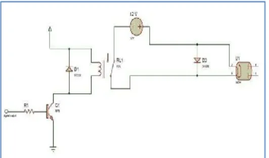
A solenoid is a simple electromagnetic device that converts electrical energy directly into linear mechanical motion, but it has a very short stroke (length of movement), which limits its applications. There are many valve design variations. Ordinary valves can have many ports and fluid paths. A 2-way valve, for example, has two ports; if the valve is open, then the two ports are connected and fluid may flow between the ports; if the valve is closed, then ports are isolated. If the valve is open when the solenoid is not energised, then the valve is termed normally open (N.O.). Similarly, if the valve is closed when the solenoid is not energised, then the valve is termed normally closed. There is also 3-way and more complicated designs. A 3-way valve has three ports; it connects one port to either of the two other ports (typically a supply port and an exhaust port). Figures 13 and Figure 14 show the physical representation of solenoid valve and driving circuitry of the solenoid valve.
Figure 13. Solenoid valve device
Figure 14. Driving circuitry of the solenoid valve
6.
SOFTWARE DESIGN
This section describes the software system design, program techniques, and system approaches used in the development of programming the microprocessor in the OWLD system. The software program is responsible for accepting data and commands, executing different commands, controlling operational terminals, and supporting data Input/output ports. This paper discusses the software in terms of routines and subroutines. The software mainly consists of two parts, one is control part, and the other is alarm part. It is intended to give a general idea of program flow and implementation.
6.1
Arduino
In the proposed system, an Arduino software from Arduino developer is used to develop program for Arduino controller. ArduinoIDE is an integrated development environment (IDE) used in computer programming. It contains a base workspace and an extensible plug-in system for customizing the environment. ArduinoIDE is written mostly in Java, but it may also be used to
develop applications in other programming languages with plug-in, including: Ada, ABAP, C, C++, etc. The environment is written in C++ and based on processing and other open-source software. This software can be used with any ARDUINO board.
The system consists of two parts: the first is the alarm, if there is one of the risks, the system sends SMS using GSM; it also decreases the risk by opening the water solenoid valves in case of leakage. When the water leaking happens, water sensor detects this risk and send the reading to Arduino, Arduino alarm the user that there is a leakage in his/her home. When the water level decrease in the tank, an ultrasonic sensor detects this decreasing and sends the reading to Arduino, Arduino alarm the user that there is a decreasing in the tank.
6.2
Android Application Development
This is an open source Android application, which has a graphical interface. An Android application is a software application that runs on the Android platform. An Android application is designed for a smartphone or a tablet running on the Android OS. Android application is written in Java programming language and use Java core libraries. Users can extend its abilities by installing plug-in written for the eclipse platform, such as development toolkits for other programming languages, and can write and contribute their own plug-in modules.
For our system software, we have many functions which are performed by the system’s circuit like acquire sensor data, process the input data, communicate with the module to send and receive data, convert the data to output, send an output signal to output modules.
We have mentioned the system consists of two parts: the second part is controlling using Android application. The application controls the pump and turns on if there is low water level in the tank. By default, the pump is off, however, when the homeowner wants to turn it on, he must enter the correct username and password, then the main facade, which contains three main parts: notifications, send instruction and about us. When the user choose to ‘send instruction’, he will see two sub parts: on and off, then he can choose to ‘on’ the pump Afterward, the message is sent to the Arduino which controls all the system, Arduino sends a message to the pump then the pump on.
For our system, the Android mobile application must allow users to control all the system by sending a message to Arduino over the network, and then commands will be issued by the microcontroller towards relays. The Android mobile application could operate seven alarm parts (six water sensors and the seventh is ultrasonic sensor) and one control part on/off the pump
6.3
FlowChart
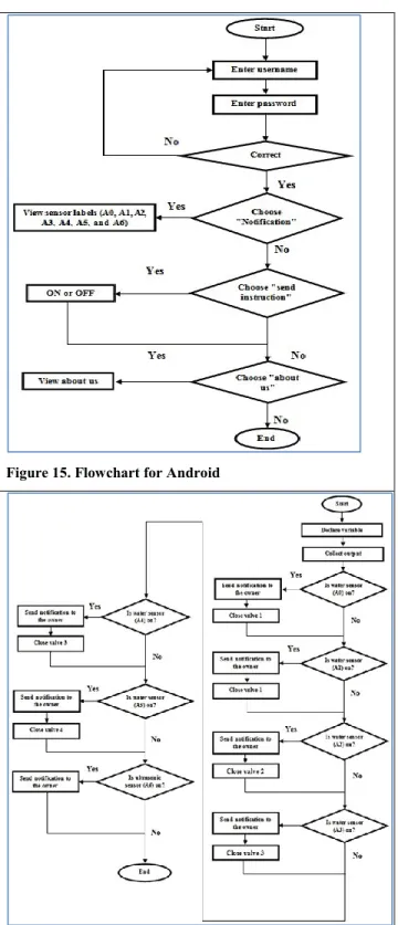
Figure 15 and Figure 16 illustrate the flow charts of the Android and Arduino, which also show process of how to turn on or turn off the system by sending SMS from user mobile phone. After the system is ‘on’, the system will check the area captured by sensors. If there is one of the risks, the system sends SMS using GSM. It also decreases the risk by opening the water solenoid valves in case of leakage.
8
Figure 15. Flowchart for Android
Figure 16. Flowchart username and password
7.
SIMULATION
The homeowner can log in to the system with the user interface window as shown in Figure 17. The homeowner enters a user name and password to securely access the system. The system can be used successfully only if the correct login information is entered.
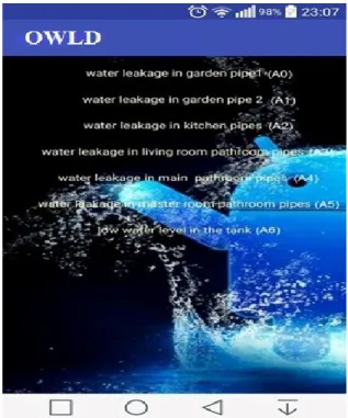
The main facade contains three main parts: notification, send instruction and about us, as shown in Figure 18. When the home owner chooses notification, he will see seven parts: six of them for water sensor (water leakage in garden pipe1, water leakage in garden pipe2, water leakage in kitchen pipes , water leakage in living room bathroom pipes , water leakage in main bathroom pipes , water leakage in master room bathroom pipes) and the seventh part for the ultrasonic sensor (low water level in the tank) as shown in Figure 19. If he chooses send instruction he will see the choice: on or off as shown in Figure 20, when he chooses one of them the message will be sent to the Arduino which is controlling all of the system. Arduino sends a message to the pump then the pump is on or off. If the user wants to see information about the application, he must click on the ’ABOUT US’ as shown in Figure 21.
Figure 17. Interface for enter username and password
9
Figure 19. Interface when owner chooses notification home
Figure 20. Interface when homeowner chooses send instruction
Figure 21. Interface when owner selects about us
8.
CONCLUSION and FUTURE WORK
The proposed systems are tested on the model of OWLD, which is shown in Figure 2. This system feature is expected to draw much attention in the next decades. The proposed system is based on technical method that deals with Android application to get wireless notification of the plumping structure when leakage occurred. In addition, this application is used to control remotely the water pump which will supply the upper tank when the water level decreased the preselected value of the controller. People getting more concerned to protect their house from water leakage. This system can monitor a house by using sensors that are integrated with a microcontroller and a GSM unit. This paper has successfully presented a functional, low cost and low complexity microcontroller based GSM security system. The proposed system has addressed the water leakage problems by proposing cost effective and reliable solution.
The future work will be on improving an insulation system that will be used to cover and protect the electrical wires, which are for the electrical supply and signal of the water sensors. These sensors are distributed on the domestic plumping network. This insulation is important to avoid damage between water hoses and the electrical wires of the sensors. Also, related to the future work of this system, we can apply this technical method of detecting water leakage in the maintenance companies to allow them be able to monitor the plumping networks in the buildings and homes faraway. In addition, this application, which was produced for the system, can be used with maintenance engineer to be notified when and where the leakage occurred to fix the problem directly. The system is developed for educational purpose and is currently in use at Computer Networks Lab at Palestine Technical University.
9.
ACKNOWLEDGMENTS
The authors would like to thank Palestine Technical University – Kadoorie (PTUK) for supporting this research and allowing us to conduct this work in the university labs. The system has developed
10 for educational purpose and is currently in use at Computer Networks Lab at Palestine Technical University
10.
REFERENCES
[1] Z. Rasin and M. Abdullah, “Water leakage Monitoring System Using Zigbee Based Wireless Sensor Network,” in International Journal Engineering &Technology, 2005.
[2] D. Misiunas, A. R. Simpson and G. Olsson, “Burst detection and location in water distribution networks,” , 5(3–4), 71–80. (2005).,”
Water Science and Technology: Water Supply, vol. 5, no. 3-4, pp. 71-80, 2005.
[3] M. Bowling, “Leakage testing method for a plate heat exchanger”. U.S Patent 6,062,068, May 16, 2000.
[4] A. S. Almazyad, Y. M. Seddiq, A. M. Alotaibi, A. Y. Al-Nasheri, A. M. Obeid and S. M. Qasim, “A Proposed Scalable Design and Simulation of Wireless Sensor Network-Based Long-Distance Water Pipeline Leakage Monitoring System,” Sensors , vol. 14, no. 2, pp. 3557-3577, 2014.
[5] F. Karray, A. Garcia-Ortiz, M. W. Jmal, A. M. Obeid and M. Abid, “EARNPIPE: A Testbed for Smart Water Pipeline Monitoring Using Wireless Sensor Network,” in 20th International Conference on Knowledge Based and Intelligent Information and Engineering, 2016.
[6] M. Hammoudeh, F. Al-Fayez, H. Lloyd, R. Newman, B. Adebisi, A. Bounceur and A. Abuarqoub, “A Wireless Sensor Network Border Monitoring System: Deployment Issues and Routing Protocols,”
IEEE Sensors Journal , vol. 17, no. 8, 2017.
[7] M. Hammoudeh, R. Newman, C. Dennett, S. Mount and O. Aldabbas, “Map as a Service: A Framework for Visualising and Maximising Information Return from Multi-ModalWireless Sensor Networks,” Sensors, vol. 15, no. 9, pp. 22970-23003, 2015. [8] S. Tarapiah, S. Atalla, K. F. B. Hashim and M. Daadoo, “Mobile
Network Planning Process Case Study-3G Network,” Computer and Information Science, vol. 9, no. 3, p. 115, 2016.
[9] Y.-A. Daraghmi and M. Daadoo, “ Intelligent Smartphone based system for detecting speed bumps and reducing car speed,” in
MATEC Web of Conferences, 2016.
[10] M. Daadoo, S. M. Atallah and S. Tarapiah, “Development of Low Cost Safety Home Automation System using GSM Network,”
European Journal of Scientific Research, vol. 53, no. 3, pp. 338-353, 2016.
[11] M. Daadoo, S. Tarapiah and S. M. Atallah, “Analysis and Performance of a Low Cost Multiple Alarm Security System for Smart Home Based on GSM Technology and Controlling Based on Android Smartphone,” European Journal of Scientific Research,
vol. 143, no. 2, pp. 136-165, 2016.
[12] A. R. Mishra, Advanced Cellular Network Planning and Optimisation, Chichester England: John Wileys & Sons Ltd, 2007. [13] M. Daadoo, S. Tarapiah and S. Atalla, “Evaluating Efficiency of
Multi-Layered Switch Architecture in All-Optical Networks,”
International Journal of Applied Engineering Research, vol. 11, no. 22, pp. 11030-11036, 2016.
[14] M. Daadoo and Y. Daraghmi, “Searching of optimum characteristics of multi-layer switching architecture in all-optical networks.,” in
11th International Conference on Heterogeneous Networking for Quality, Reliability, Security and Robustness (QSHINE), 2015.