UNIVERSITAT POLITÈCNICA DE CATALUNYA
(UPC) - BARCELONATECH
FACULTAT D’INFORMÀTICA DE BARCELONA (FIB)
MASTER IN INNOVATION AND RESEARCH IN
INFORMATICS (MIRI)
HIGH PERFORMANCE COMPUTING (HPC)
Enabling Analytic and HPC Workflows with
COMPSs
F
INAL
M
ASTER
T
HESIS
(FMT)
2016-2017 | A
UTUMN
S
EMESTER
Author:
Cristián R
AMÓN
-C
ORTÉS
V
ILARRODONA
Supervisor:
Dra. Rosa M. B
ADIA
S
ALA
iii
"En esto, descubrieron treinta o cuarenta molinos
de viento que hay en aquel campo, y así como
don Quijote los vio, dijo a su escudero:
-La ventura va guiando nuestras cosas mejor
de lo que acertáramos a desear; porque ves allí,
amigo Sancho Panza, donde se descubren treinta,
o pocos más, desaforados gigantes, con quien
pienso hacer batalla y quitarles a todos las vidas,
con cuyos despojos comenzaremos a enriquecer;
que ésta es buena guerra, y es gran servicio de
Dios quitar tan mala simiente de sobre la faz de la
tierra.
-¿Qué gigantes? -dijo Sancho Panza.
-Aquéllos que allí ves -respondió su amo- de los
brazos largos, que los suelen tener algunos de casi
dos leguas.
-Mire vuestra merced -respondió Sancho- que
aquéllos que allí se parecen no son gigantes,
sino molinos de viento, y lo que en ellos parecen
brazos son las aspas, que, volteadas del viento,
hacen andar la piedra del molino.
-Bien parece -respondió don Quijote- que no
estás cursado en esto de las aventuras: ellos son
gigantes...que yo voy a entrar con ellos en fiera y
desigual batalla.
Y diciendo esto, dio de espuelas a su caballo
Roci-nante, sin atender a las voces que su escudero
San-cho le daba, advirtiéndole que, sin duda alguna,
eran molinos de viento, y no gigantes...”
Miguel de Cervantes Saavedra,
Don Quijote de la Mancha
v
Dedication
Facing a challenging work needs self-efforts as well as the
patience of the people around us, especially from our peers.
To my loving mother and father, Dolors and Joan, whose love,
encouragement and gentle prodding guided me to such a
success. I hope that this work will complete the dream they
had for me many years ago when they chose to give me the
best education they could.
Special thanks to my sweet sister, Marta, whose affection and
support keeps me always up.
Last but not least, I cannot forget Laura, who did more than her
share around the house as I was locked in the computer room.
Without her unconditional love and constant encouragement,
this would not have been possible.
Wholeheartedly,
vii
Declaration of Authorship
I hereby declare that, except where specific reference is made to the work of others, this
Master’s thesis has been composed by me and it is based on my own work. None of the
contents of this dissertation have been previously published nor submitted, in whole or in
part, to any other examination in this or any other university.
Signed:
ix
Acknowledgements
I gratefully thank my supervisor Rosa M. Badia Sala for all her assistance during my
career at the
Barcelona Supercomputing Center (BSC-CNS)
and for giving me the opportunity
to collaborate on this project.
I would also like to thank all my colleagues, current and former members of the
Work-flows and Distributed Computing
team from the
Barcelona Supercomputing Center (BSC)
for their
useful comments, remarks and engagement through the learning process of this Master’s
thesis: Jorge Ejarque, Francesc Lordan, Francisco Javier Conejero, Raul Sirvent, Daniele
Lezzi, Pol Alvarez, Ramon Amela, Sandra Corella, Albert Serven, Adrià Aguilà and
Ser-gio Rodríguez.
Special thanks to Kim Serradell Maronda for giving me the opportunity to work with
the
NMMB
application and guiding me through its internals.
xi
UNIVERSITAT POLITÈCNICA DE CATALUNYA (UPC) - BARCELONATECH
Facultat d’Informàtica de Barcelona (FIB)
MASTER IN INNOVATION AND RESEARCH IN INFORMATICS (MIRI)
High Performance Computing (HPC)
Abstract
Enabling Analytic and HPC Workflows with COMPSs
by Cristián R
AMÓN
-C
ORTÉS
V
ILARRODONA
In the recent joint venture between High-Performance Computing (HPC) and Big-Data
(BD) Ecosystems towards the Exascale Computing, the scientific community has realized
that powerful programming models and high-level abstraction tools are a must. Within this
context, the Barcelona Supercomputing Center (BSC) is developing the COMP Superscalar
(COMPSs) programming model, whose main objective is to develop applications in a
se-quential way, while the Runtime System handles the inherent parallelism of the application
and abstracts the programmer from the different underlying infrastructures. The parallelism
is achieved by defining an application Interface that allows COMPSs to detect methods that
operate on a set of parameters (called tasks), and execute them distributedly and
transpar-ently.
This Master Thesis aims to enhance COMPSs, adapting it to the needs of the Big-Data
Ecosystems, by supporting Analytic and HPC workflows. To this end, we propose a
straight-forward integration with the execution of binaries, and
MPI
and
OmpSs
applications.
Al-though the COMPSs programming model is kept untouched, we extend the COMPSs
An-notations and some of the COMPSs internals such as the task schedulers and the worker
executors.
To support our contribution, we have ported to COMPSs two real use cases. On the
one hand,
NMMB BSC-Dust
, a workflow to predict the atmospheric life cycle of the desert
dust and, on the other hand,
Guidance
, an integrated solution for Genome and Phenome
association analysis.
xiii
Contents
Dedication
v
Declaration of Authorship
vii
Acknowledgements
ix
Abstract
xi
1
Introduction
1
1.1
Motivation . . . .
1
1.2
Context . . . .
2
1.3
Objectives . . . .
2
1.3.1
Detailed Objectives . . . .
2
1.4
Document Structure . . . .
2
2
State of the art
5
2.1
Distributed libraries . . . .
5
2.1.1
MPI . . . .
5
2.1.2
Sockets . . . .
8
2.2
Workflow Frameworks . . . .
11
2.2.1
Frameworks with explicit workflows’ definition . . . .
11
2.2.1.1
Taverna . . . .
11
2.2.1.2
Fireworks . . . .
12
2.2.1.3
Kepler . . . .
14
2.2.1.4
Galaxy . . . .
15
2.2.2
Frameworks with implicit workflows’ definition . . . .
16
2.2.2.1
MapReduce . . . .
16
2.2.2.2
Spark . . . .
18
2.2.2.3
Swift . . . .
20
2.2.2.4
COMP Superscalar (COMPSs) . . . .
22
3
COMPSs overview
23
3.1
Programming Model . . . .
24
3.2
Runtime System . . . .
27
3.3
Task Workflow . . . .
29
4
Tools and methodology
31
4.1
Tools . . . .
31
4.2
Methodology . . . .
31
4.2.1
Scientific method design . . . .
31
4.2.2
Development strategy . . . .
32
xiv
5
Implementation
33
5.1
Programming model annotations . . . .
33
5.1.1
New task annotations . . . .
33
5.1.2
Environment variables as annotations . . . .
35
5.1.3
Versioning task annotation . . . .
38
5.1.4
SchedulerHints task annotation . . . .
40
5.1.5
New stream parameter annotation . . . .
41
5.1.6
New prefix parameter annotation . . . .
42
5.2
Scheduling modifications . . . .
45
5.2.1
Treatment of non-native tasks . . . .
45
5.2.2
Multi-node execution actions . . . .
45
5.2.3
Treatment of SchedulerHints . . . .
48
5.3
Worker enhancements . . . .
48
5.3.1
Invokers . . . .
49
5.3.2
External executors enhancement . . . .
50
6
Results and evaluation
53
6.1
Proofs of concept . . . .
53
6.1.1
BLAST . . . .
53
6.1.1.1
Application description . . . .
53
6.1.1.2
Purpose . . . .
54
6.1.1.3
Evaluation . . . .
54
6.1.2
Matmul . . . .
58
6.1.2.1
Application description . . . .
58
6.1.2.2
Purpose . . . .
59
6.1.2.3
Hybrid COMPSs and MPI Matmul implementation . . . . .
59
6.1.2.4
Evaluation . . . .
61
6.2
Use cases . . . .
64
6.2.1
NMMB/BSC-Dust . . . .
64
6.2.1.1
Application description . . . .
64
6.2.1.2
Purpose . . . .
64
6.2.1.3
NMMB/BSC-Dust implementation with COMPSs . . . .
65
6.2.1.4
Evaluation . . . .
66
6.2.2
GUIDANCE . . . .
70
6.2.2.1
Application description . . . .
70
6.2.2.2
Purpose . . . .
71
6.2.2.3
GUIDANCE implementation with COMPSs . . . .
71
6.2.2.4
Evaluation . . . .
73
7
Conclusions and Future work
75
Bibliography
77
Appendices
81
A Blast: complete code
83
A.1 Blast.java . . . .
83
A.2 BlastItf.java . . . .
86
A.3 BlastImpl.java . . . .
87
xv
B Matmul: complete code
89
B.1 Matmul.java . . . .
89
B.2 MatmulItf.java . . . .
91
B.3 MatmulImpl.java . . . .
92
B.4 MPI.java . . . .
93
B.5 Matmul.c . . . .
93
B.6 Block.java . . . .
95
C NMMB/BSC-Dust: code highlights
99
C.1 Nmmb.java . . . .
99
C.2 NmmbItf.java . . . 112
D GUIDANCE: code highlights
121
D.1 Guidance.java . . . 121
xvii
List of Figures
2.1
MPI Hello example in C . . . .
6
2.2
MPI Hello execution example . . . .
7
2.3
MPI Hello diagram of execution . . . .
7
2.4
Main code of Java Hello example with Sockets . . . .
8
2.5
Master process code of Java Hello example with Sockets . . . .
9
2.6
Slave process code of Java Hello example with Sockets . . . .
10
2.7
Execution example of Hello with Sockets . . . .
11
2.8
BLAST design example using Taverna . . . .
12
2.9
FireWorks components . . . .
12
2.10 Workflows’ components in FireWorks . . . .
13
2.11 Example of Workflow using FireWorks . . . .
13
2.12 Lotka-Volterra workflow example using Kepler . . . .
14
2.13 Galaxy graphical web-based platform to define Workflows . . . .
15
2.14 Galaxy graphical web-based platform to execute Workflows . . . .
16
2.15 Wordcount example on top of
Hadoop
. . . .
17
2.16 Execution example of Wordcount using MapReduce . . . .
18
2.17 Spark’s Components . . . .
19
2.18 Wordcount example in Java using Spark . . . .
20
2.19 Swift programming language . . . .
21
2.20 Swift simulation workflow example . . . .
21
2.21 Swift simulation code example . . . .
22
3.1
COMPSs overview . . . .
23
3.2
Increment main class . . . .
24
3.3
Increment helper methods class . . . .
25
3.4
Increment Interface . . . .
25
3.5
Sequential execution example of Increment . . . .
26
3.6
COMPSs execution example of Increment . . . .
26
3.7
COMPSs structure . . . .
27
3.8
COMPSs Runtime overview . . . .
28
3.9
COMPSs task execution workflow . . . .
29
5.1
Binary annotation . . . .
34
5.2
Complete Binary annotation . . . .
34
5.3
MPI annotation . . . .
34
5.4
Complete MPI annotation . . . .
34
5.5
OmpSs annotation . . . .
35
5.6
Complete OmpSs annotation . . . .
35
5.7
Wordcount Interface . . . .
35
5.8
Wordcount executions with different constraint values . . . .
36
5.9
Wordcount Interface with environment variables . . . .
36
5.10 Wordcount executions with environment variables as constraints . . . .
36
xviii
5.12 Example of complex environment variables on the
workingDir
field . . . .
38
5.13 Example of previous versionning main code . . . .
38
5.14 Example of previous versionning implementation 1 code . . . .
38
5.15 Example of previous versionning implementation 2 code . . . .
39
5.16 Example of the Interface of previous versionning . . . .
39
5.17 Example of the Interface of previous versionning with constraints . . . .
39
5.18 Example of the new Annotation Interface . . . .
40
5.19 Extended example of the new Annotation Interface . . . .
40
5.20 Example of an Interface with SchedulerHints . . . .
41
5.21 Example of the different return types of the non-native tasks . . . .
41
5.22 Example of the different stream annotations for non-native tasks . . . .
42
5.23 Binary Tasks example for joint prefixes . . . .
43
5.24 Main code example for joint prefixes . . . .
43
5.25 Interface example of an application with prefixes . . . .
44
5.26 Example of the main code calls to tasks with prefixes . . . .
44
5.27 Example of the command executed inside each task using prefixes . . . .
45
5.28 Example of a single node task flow . . . .
46
5.29 Example of a multi-node task flow . . . .
47
5.30 New structure of the COMPSs Worker Executors . . . .
50
5.31 Execution time versus number of
ProcessBuilders
or Pipes . . . .
51
6.1
Execution arguments of the COMPSs BLAST application . . . .
53
6.2
Example of BLAST execution with N = 8 . . . .
54
6.3
COMPSs BLAST application: new
align
task implementation . . . .
54
6.4
COMPSs BLAST application: old
align
task implementation . . . .
55
6.5
COMPSs BLAST application: new
align
task call . . . .
55
6.6
COMPSs BLAST application: old
align
task call . . . .
56
6.7
COMPSs BLAST application: new
align
’s interface annotation . . . .
56
6.8
COMPSs BLAST application: old
align
’s interface annotation . . . .
56
6.9
Multiplication of a Matrix divided in blocks . . . .
58
6.10 Task execution graph of a
Matmul
example . . . .
59
6.11 Hybrid COMPSs and MPI block layers . . . .
60
6.12 Main multiplication loop of the Hybrid
Matmul
. . . .
60
6.13
multiplyAccumulative
’s interface annotation for the Hybrid COMPSs and MPI
Matmul
. . . .
61
6.14
Matmul
Strong Scaling analysis . . . .
62
6.15
Matmul
Weak Scaling analysis . . . .
62
6.16 Example of four hour average AOD from NMMB/BSC-Dust . . . .
64
6.17 NMMB/BSC-Dust step workflow . . . .
65
6.18 NCVIEW plots of FIS 3D variable for both implementations . . . .
66
6.19 NCVIEW plot of PS 3D variable for both implementations . . . .
66
6.20 NCVIEW plot of SLP 3D variable for both implementations . . . .
67
6.21 Tasks graph of NMMB/BSC-Dust with COMPSs . . . .
68
6.22 Paraver task view of the NMMB/BSC-Dust execution with COMPSs . . . . .
68
6.23 GUIDANCE’s schematic representation of the typical complete Genome and
Phenome association analysis . . . .
70
6.24 Example of previous GUIDANCE binary task implementation . . . .
71
xix
List of Tables
3.1
Useful arguments for the
runcompss
command . . . .
27
5.1
Available fields for the
SchedulerHints
annotation . . . .
40
5.2
Available stream types with their valid directions and execution behaviour .
42
6.1
Execution parameters of the BLAST application . . . .
57
6.2
Task times . . . .
57
6.3
NMMB/BSC-Dust code summary . . . .
65
6.4
Execution times of the different NMMB/BSC-Dust implementations for the
simulation of 1 day of global domain with 64 cores . . . .
67
6.5
GUIDANCE code summary . . . .
73
xxi
List of Abbreviations
API
A
pplication
P
rogramming
I
nterface
COMPSs
COMP S
uperscalar
CPU
C
entral
P
rocessing
U
nit
GUI
G
raphical
U
ser
I
nterface
I/O
I
nput /
O
utput
MPI
M
essage
P
assing
I
nterface
NEMS
N
OAA
E
nvironmental
M
odeling
S
ystem
NMMB
N
onhydrostatic
M
ultiscale
M
odel on the
B
-grid
NOAA
N
ational
O
ceanic and
A
tmospheric
A
dministration
OS
O
perating
S
ystem
PyCOMPSs
Py
thon binding for
COMP S
uperscalar
RAM
R
andom
A
ccess
M
emory
SSH
S
ecure
SH
ell
VM
V
irtual
M
achine
xxiii
Glossary
CPU
The Central Processing Unit (CPU) is the part of the computer that contains all the
ele-ments required to execute the instructions of software programs. Its main components are
the main memory, the Processing Unit (PU) and the Control Unit (CU). Modern computers
use multi-core processors, which are a single chip containing one or more cores.
Core
A core is an individual processor that actually executes program instructions. Current
single chip CPUs contain many cores and are referred as multi-processor or multi-cores.
MareNostrum III
MareNostrum III is the most powerful supercomputer in Spain with 3056 nodes (48.896
processors), 115.5 TB of main memory and a peak performance of 1.1 Petaflops. It is hosted
by the Barcelona Supercomputing Center (BSC).
Node
A compute node refers to a single system within a cluster of many systems.
Scratch Space
Supercomputers generally have what is called scratch space: disk space available for
temporary use and only accessible from the compute nodes.
SSH
A protocol to securely connect to a remote computer. This connection is generally for a
command line interface, but it is possible to use GUI programs through SSH.
Environment Variable
In Linux systems, each process has an execution environment. This environment can
be inherited from the user session environment and can be extended with specific process
variables. An Environment Variable is a value stored in the process environment that can
affect its execution.
API
An Application Programming Interface (API) is a set of methods and functions that are
used by another software to produce an abstraction layer.
Operating System
A system software that manages the hardware and provides services for computer
soft-ware.
xxiv
Framework
Framework stands for a set of standardized concepts, practices or criterias used to face a
given problem. Specifically, it defines a set of programs, libraries, languages, and
program-ming models used jointly in a project.
Workflow
A workflow is composed of tasks and dependencies between tasks. Workflows are
com-monly represented as graphs, with the nodes beeing tasks and the arrows representing the
dependencies. Somehow, tasks must represent an action that must be done (i.e. the
ex-ecution of a binary), and the dependencies must represent the requirements that must be
satisfied to be able to execute the task (i.e. the machine availability or the required data).
Binary
A file containing a list of machine code instructions to perform a list of tasks.
WSDL
Web Services Description Language (WSDL) is an Extensible Markup Language (XML)
used to describe web services.
Graphical User Interface
The GUI is a software that graphically interacts with the user of a computer to ease the
data manipulation.
1
Chapter 1
Introduction
1.1
Motivation
Several years ago the industry required the research community to shift from sequential
computing to parallel computing. The extreme increase in the computational loads and the
decrease of the acceptable system’s response time forced the community to “think in
paral-lel”. Although writing parallel codes is not as easy as writting sequential programs, we can
assume that the actual computing resources of a multi-core processor are already able to
ex-ploit the inherent instruction-level parallelism of an application in a completely transparent
way for programmers.
However, the next generation of applications were requiring more high-performance
computing resources than those that a single computing resource could offer. Thus, it
was necessary to use many machines communicated through networks to achieve a larger
amount of computing capabilities. That is what we know today as
Distributed Computing
.
Distributed applications exploit the
task-level
parallelism and are even more difficult to
han-dle for programmers. One of the major issues that araise from both parallel and distributed
programming is that writing in parallel is not as easy as writting sequential programs and,
more often than expected, people that can develop useful and complete end-user
applica-tions is not capable of writting efficient parallel code (and the other way arround). We can
somehow consider that scientists interpreting results do not care about the computational
load or distribution (how results are computed), but care of the results quality, the time spent
to retrieve the results and the robustness of the system. In this line of
“writing programs that
scale with increasing number of cores should be as easy as writing programs for sequential
com-puters”
[3] several programming models have araised to help the programmer handle the
underlying infrastructure.
Nowadays, the scientific community not only wants to work in parallel and distributed
systems but also needs to handle a large amount of data. In this sense,
Big-Data (BD)
Ecosys-tems
appeared some years ago; allowing the community to store, check, retrieve and
trans-form enormous amounts of data in acceptable response times. For this purpose, several
programming models have also arised but are completely different to the ones used by the
High Performance Computing
community.
In the race towards the Exascale Computing [2], the scientific community has realized
that unifying
High Performance Computing (HPC)
platforms and
Big-Data (BD) Ecosystems
is a
must
. Nowadays, these two ecosystems differ significantly at hardware and software level
but
“programming models and tools are perhaps the biggest point of divergence between the
scientific-computing and big-data ecosystems”
[50]. In this respect,
“there is a clear desire on the part of a
number of domain and computer scientists to see a convergence between the two high-level types of
computing systems, software, and applications: Big Data Analytics (BDA) and High Performance
2
Chapter 1. Introduction
Computing (HPC)”
[22]. We can then conclude that the joint venture between HPC and BDA
ecosystems opens a great oportunity for programming models that is worth to investigate.
1.2
Context
The current project is conducted as the
Final Master Thesis
in the
Master of Innovation and
Research in Informatics - High Performance Computing (MIRI - HPC)
offered by the
Universitat
Politecnica de Catalunya (UPC)
[16] and has been funded by the
Barcelona Supercomputing
Center (BSC)
[7].
The project has been developed as a research support engineer in the
Workflows and
Dis-tributed Computing
group of the
Computer Science
department at the
BSC
. The main goal of
this group is to ease the development of applications and services for distributed
infras-tructures (such as Clusters, Grids and Clouds) through the
COMP Superscalar (COMPSs)
[19] programming model. The group also covers Big-Data and HPC applications, energy
constrained environments, GPU offloading and execution in mobile devices.
1.3
Objectives
To take profit of the abovementioned join venture between HPC and BDA ecosystems
this Final Master Thesis
enhances the
COMPSs
Framework to support Analytic and HPC
workflows
. In next subsection we provide detailed information about the specific objectives
that have been considered to successfully achieve this contribution.
1.3.1
Detailed Objectives
The following points summarize the main goals of the project:
O1
Conduct a survey among the Analytic and HPC workflows to determine the most
common used technologies, compare them to the solutions proposed by other state of
the art Workflow Managers and determine the most adequate and feasible features for
COMPSs.
O2
Extend the current COMPSs syntax to support the selected features in a non-invasive
way; keeping the backward compatibility. More specifically, extend the COMPSs
anno-tations to support binary, MPI and OmpSs tasks.
O3
Enhance the current COMPSs Runtime by implementing the required mechanisms
to schedule and execute the new type of tasks. At scheduling level, this objective
in-cludes the treatement of multi-node tasks and the inclusion of scheduler hints for a
cer-tain type of tasks. At execution level, the COMPSs workers must transparently execute
the different kind of tasks.
O4
Demonstrate that the proposal is able to execute Analytic and HPC Workflows by
executing and analysing real use-cases.
1.4
Document Structure
The rest of the document is organized as follows. Chapter 2 gives an overview of the
cur-rent state of the art of HPC and Analytic workflows, describing the most used technologies
and comparing them to what is supported in the most common Workflow Managers.
Chap-ter 3 introduces the COMPSs programming model, describing its main features before our
1.4. Document Structure
3
contribution. Chapter 4 introduces describes the tools and the development methodology
followed during all the project. Chapter 5 accurately describes our contribution to provide
the reader a closer look of the solutions that we have chosen to face each specific challenge.
Chapter 6 evaluates the obtained results and the performance of our proposal. Chapter 7
provides a brief summary of the thesis and, finally, in Chapter 8 we discuss the conclusions
and state the guidelines for the future work.
5
Chapter 2
State of the art
Scientific programs from different fields (such as bioinformatics, biomechanics, earth
sci-ences or engineering simulations) that are either computationally intensive or require a huge
amount of storage capabilities are known as
e-Science
applications. In the past decade, the
computational and storage requirements of these
e-Science
applications have grown enough
to do not fit in a single machine. This fact has forced
e-Science
applications to move from
par-allel computing to distributed computing because the computing resources within a
multi-core processor are limited by the architecture and the technology of the system and were
already fully exploited. However, in the distributed computing paradigm, the only room
for improvements is to exploit the
task-based
parallelism between nodes.
Considering that writing applications for parallel or distributed environments is much
more difficult than writing sequential programs due to the concurrency issues, the IT
com-munity has developed several libraries and frameworks to ease the development of
applica-tions (and consequently, the development of
e-Science
applications). In an attempt to classify
all the tools provided by the community that can be used for the design of
e-Science
applica-tions, we have divided them into two groups:
Distributed Libraries
and
Workflow Frameworks
.
Next, Section 2.1 defines and provides examples of some state of the art
Distributed Libraries
and, Section, 2.2 defines and introducing some state of the art
Workflow Frameworks
.
2.1
Distributed libraries
On the one hand, distributed computing can be achieved by programming the low-level
communication between processes. Although using distributed libraries can lead to
excel-lent performance results, it is a tedious work for the programmer to develop efficient code
for a complex application using such libraries. Next subsections provide some examples of
these libraries.
2.1.1
MPI
The Message-Passing Interface (
MPI
) standard
“includes point-to-point message-passing,
collective communications, group and communicator concepts, process topologies, environmental
management, process creation and management, one-sided communications, extended collective
op-erations, external interfaces, I/O, some miscellaneous topics, and a profiling interface”
[38]. The
MPI standard includes bindings for C and Fortran, and its goal is
“to develop a widely used
standard for writing message-passing programs”
[38]. It has several different implementations
but the most well-known are
OpenMPI
[54] and
IMPI
[30]).
For the end user, using MPI requires handling explicitly the spawn of the processes, the
code executed by each process and the communication between them. All this management
is done by using API calls, and thus, the application code must be compiled and executed
with the MPI compiler of the specific MPI implementation. The main advantage is that the
users have full control of all the processes and the communication between them which, for
6
Chapter 2. State of the art
experienced users, leads to high efficient codes. However, for inexperienced users, an
effi-cient code can become unreadable and handle many processes can become a tedious work.
Moreover, when porting a sequential application to an MPI application, the users must
ex-plicitly distribute the data between the processes and retrieve back the results (which can
lead to load imbalance or inefficient communications). Additionally, another inconvenience
of MPI is that, once the application’s execution has started, the number of processes cannot
be changed dinamically, limiting the maleability of the applications.
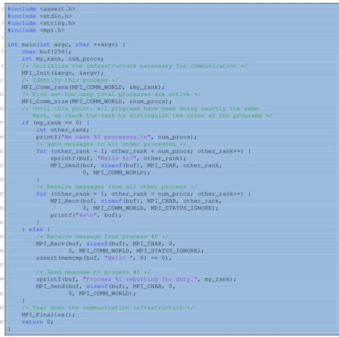
Figure 2.1 shows an example of an MPI application written in C. The code spawns a
given number of processes, sets up one process as coordinator and the rest as slaves that
send back a message to the coordinator saying that they are ready to work. As seen in the
figure, each process has a unique identifier, and the communication between them is done
by using the MPI_Send or MPI_Receive API calls (obviously, more complex programs will
require more complex API calls).
1 #include <assert.h>
#include <stdio.h>
3 #include <string.h>
#include <mpi.h>
5
int main(int argc, char **argv) {
7 char buf[256];
int my_rank, num_procs;
9 /* Initialize the infrastructure necessary for communication */
MPI_Init(&argc, &argv);
11 /* Identify this process */
MPI_Comm_rank(MPI_COMM_WORLD, &my_rank);
13 /* Find out how many total processes are active */
MPI_Comm_size(MPI_COMM_WORLD, &num_procs);
15 /* Until this point, all programs have been doing exactly the same. Here, we check the rank to distinguish the roles of the programs */
17 if (my_rank == 0) {
int other_rank;
19 printf("We have %i processes.\n", num_procs);
/* Send messages to all other processes */
21 for (other_rank = 1; other_rank < num_procs; other_rank++) { sprintf(buf, "Hello %i!", other_rank);
23 MPI_Send(buf, sizeof(buf), MPI_CHAR, other_rank, 0, MPI_COMM_WORLD);
25 }
/* Receive messages from all other process */
27 for (other_rank = 1; other_rank < num_procs; other_rank++) { MPI_Recv(buf, sizeof(buf), MPI_CHAR, other_rank,
29 0, MPI_COMM_WORLD, MPI_STATUS_IGNORE); printf("%s\n", buf);
31 }
} else {
33 /* Receive message from process #0 */
MPI_Recv(buf, sizeof(buf), MPI_CHAR, 0,
35 0, MPI_COMM_WORLD, MPI_STATUS_IGNORE); assert(memcmp(buf, "Hello ", 6) == 0),
37
/* Send message to process #0 */
39 sprintf(buf, "Process %i reporting for duty.", my_rank); MPI_Send(buf, sizeof(buf), MPI_CHAR, 0,
41 0, MPI_COMM_WORLD); }
43 /* Tear down the communication infrastructure */
MPI_Finalize();
45 return 0; }
F
IGURE2.1: MPI Hello example in C.
Source: Wikipedia, Message Passing Interface
2.1. Distributed libraries
7
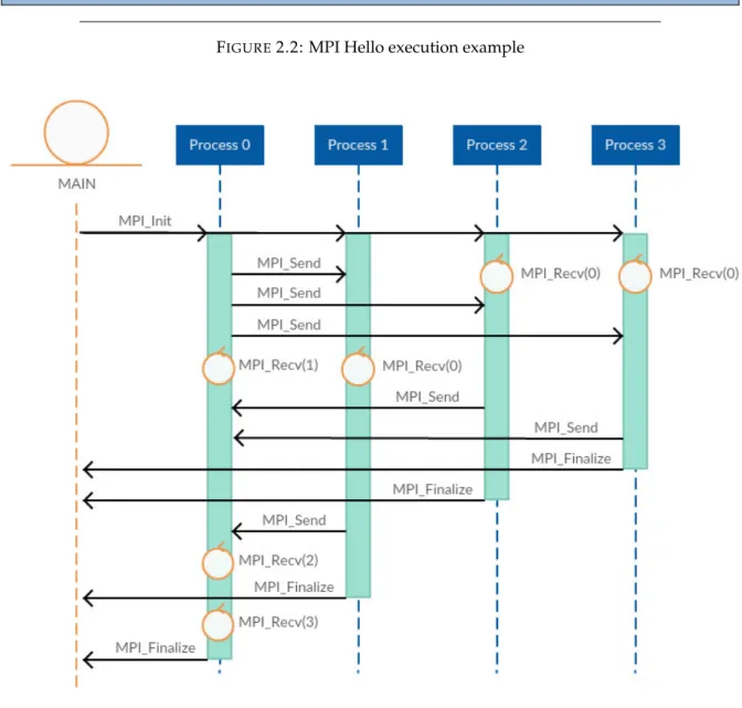
Figure 2.2 shows the command line result and Figure 2.3 shows a diagram of executing
the aforementioned code with 4 processes. Notice that the spawn time of the processes and
the communication between them is not always done at the same time and thus, the diagram
is only one of the possible execution diagrams of the same code. For instance, Process 0 will
always send messages to Processes 1, 2 and 3 in the same order and will receive the messages
back in the same order, but Processes 1, 2 and 3 can receive the message in different orders
and send the reply in different orders. This issue is one of the hardest things to overcome
when developing applications with MPI because blocking processes in a receive call can lead
to significant overheads. For instance, in our diagram, Processes 2 and 3 have sent all their
data, but Process 0 does not receive the message until the data from Process 1 is received.
1 $ mpicc example.c $ mpirun -n 4 ./a.out
3 We have 4 processes.
Process 1 reporting for duty.
5 Process 2 reporting for duty. Process 3 reporting for duty.
F
IGURE2.2: MPI Hello execution example
8
Chapter 2. State of the art
2.1.2
Sockets
A Socket[42] is an endpoint on a machine to send and receive data and can be used
either to communicate processes within the same machine or through the network. Each
process refers to a socket by means of a
Socket Descriptor
and then establishes a connection
through the socket creating a
Channel
. The underlying Operating System of the machine
provides a socket API, but applications normally use a higher-level API implementation
that depends on its language (for example, sys/socket.h for C [26], socket library for Python
[49] or java.net.Socket for Java [40]).
Like the previous case, for the end user, using Sockets only enables the communication
between different processes. Thus, it requires handling explicitly the spawn of the
pro-cesses, the code executed by each process and the communication between them. Since the
application will also use an API, the source code must be developed using this
underly-ing technology and compiled accordunderly-ingly. However, contrary to MPI, it does not require a
specific compiler.
The next figures show the same example than the MPI case but written in Java and using
Java Sockets. Figure 2.4 contains the main code to initialize and spawn all the processes.
package helloSocket;
2
public class HelloSocket {
4
private static final int BASE_SOCKET_PORT = 47_000;
6 private static int numThreads;
private static int[] socketPorts;
8
public static void main(String args[]) {
10 // Get arguments
if (args.length < 1) {
12 System.err.print("[ERROR] Invalid usage");
System.err.print(" Usage: ./main <numThreads>");
14 System.exit(1); }
16 numThreads = Integer.valueOf(args[0]);
// Create the array of usable ports
18 socketPorts = new int[numThreads];
for (int i = 0; i < numThreads; ++i) {
20 socketPorts[i] = BASE_SOCKET_PORT + i; }
22
Thread[] procs = new Thread[numThreads];
24 // Spawn the master process
procs[0] = new MasterProcess(numThreads, socketPorts);
26 procs[0].start();
// Spawn the slave processes
28 for (int i = 1; i < numThreads; ++i) {
procs[i] = new SlaveProcess(i, socketPorts[i]);
30 procs[i].start(); }
32
// Join the processes
34 for (int i = 0; i < numThreads; ++i) {
try {
36 procs[i].join();
} catch (InterruptedException ie) {
38 Thread.currentThread().interrupt(); }
40 }
}
42 }
2.1. Distributed libraries
9
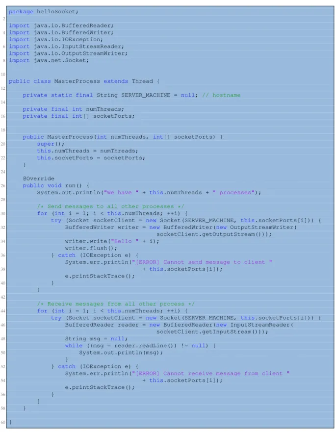
Figure 2.5 contains the code for the main process (the coordinator).
package helloSocket; 2 import java.io.BufferedReader; 4 import java.io.BufferedWriter; import java.io.IOException; 6 import java.io.InputStreamReader; import java.io.OutputStreamWriter; 8 import java.net.Socket; 10
public class MasterProcess extends Thread {
12
private static final String SERVER_MACHINE = null; // hostname
14
private final int numThreads;
16 private final int[] socketPorts;
18
public MasterProcess(int numThreads, int[] socketPorts) {
20 super();
this.numThreads = numThreads;
22 this.socketPorts = socketPorts; }
24
@Override
26 public void run() {
System.out.println("We have " + this.numThreads + " processes");
28
/* Send messages to all other processes */
30 for (int i = 1; i < this.numThreads; ++i) {
try (Socket socketClient = new Socket(SERVER_MACHINE, this.socketPorts[i])) {
32 BufferedWriter writer = new BufferedWriter(new OutputStreamWriter( socketClient.getOutputStream()));
34 writer.write("Hello " + i); writer.flush();
36 } catch (IOException e) {
System.err.println("[ERROR] Cannot send message to client " 38 + this.socketPorts[i]);
e.printStackTrace();
40 }
}
42
/* Receive messages from all other process */
44 for (int i = 1; i < this.numThreads; ++i) {
try (Socket socketClient = new Socket(SERVER_MACHINE, this.socketPorts[i])) {
46 BufferedReader reader = new BufferedReader(new InputStreamReader( socketClient.getInputStream()));
48 String msg = null;
while ((msg = reader.readLine()) != null) {
50 System.out.println(msg); }
52 } catch (IOException e) {
System.err.println("[ERROR] Cannot receive message from client " 54 + this.socketPorts[i]); e.printStackTrace(); 56 } } 58 } 60 }
10
Chapter 2. State of the art
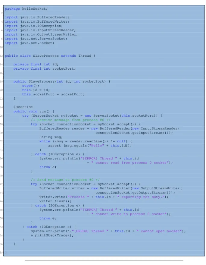
Figure 2.6 contains the code for the slave processes.
package helloSocket; 2 import java.io.BufferedReader; 4 import java.io.BufferedWriter; import java.io.IOException; 6 import java.io.InputStreamReader; import java.io.OutputStreamWriter; 8 import java.net.ServerSocket; import java.net.Socket; 10
12 public class SlaveProcess extends Thread {
14 private final int id;
private final int socketPort;
16
18 public SlaveProcess(int id, int socketPort) {
super();
20 this.id = id;
this.socketPort = socketPort;
22 }
24 @Override
public void run() {
26 try (ServerSocket mySocket = new ServerSocket(this.socketPort)) {
/* Receive message from process #0 */
28 try (Socket connectionSocket = mySocket.accept()) {
BufferedReader reader = new BufferedReader(new InputStreamReader(
30 connectionSocket.getInputStream())); String msg;
32 while ((msg = reader.readLine()) != null) { assert (msg.equals("Hello" + this.id));
34 }
} catch (IOException e) {
36 System.err.println("[ERROR] Thread " + this.id
+ " cannot read from process 0 socket");
38 throw e;
}
40
/* Send message to process #0 */
42 try (Socket connectionSocket = mySocket.accept()) {
BufferedWriter writer = new BufferedWriter(new OutputStreamWriter(
44 connectionSocket.getOutputStream())); writer.write("Process " + this.id + " reporting for duty.");
46 writer.flush(); } catch (IOException e) {
48 System.err.println("[ERROR] Thread " + this.id
+ " cannot write to process 0 socket");
50 throw e;
}
52 } catch (IOException e) {
System.err.println("[ERROR] Thread " + this.id + " cannot open socket");
54 e.printStackTrace(); }
56 }
58 }
F
IGURE2.6: Slave process code of Java Hello example with Sockets
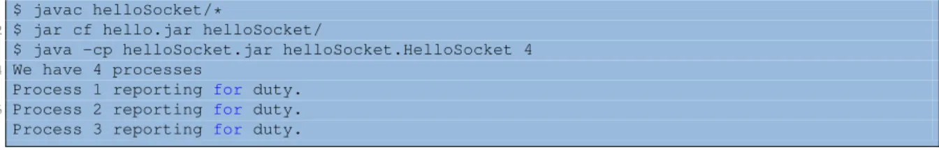
Notice that, like in the previous case, since the master process reads the messages in an
ordered manner, the execution output is always the same (see Figure 2.7) even if the process
spawn order and the messages’ arrival can vary between executions.
2.2. Workflow Frameworks
11
$ javac helloSocket/*
2 $ jar cf hello.jar helloSocket/
$ java -cp helloSocket.jar helloSocket.HelloSocket 4
4 We have 4 processes
Process 1 reporting for duty.
6 Process 2 reporting for duty. Process 3 reporting for duty.
F
IGURE2.7: Execution example of Hello with Sockets
2.2
Workflow Frameworks
On the other hand, distributed computing can also be achieved by using a workflow
framework. Frameworks are designed to encapsulate a programming model, a runtime
or even a programming language that eases the development of distributed applications.
Although all the frameworks hide the communication mechanisms between the different
processes, they can be classified regarding its task definition. Thus, subsection 2.2.2
pro-vides several examples of
frameworks with implicit workflows’ definition
and subsection 2.2.1
provides several other examples of
frameworks with explicit workflows’ definition
.
2.2.1
Frameworks with explicit workflows’ definition
Frameworks with explicit workflows’ definition allow the users to design the full
appli-cation workflow using a receipt file or a visualization tool. The main advantage is that the
users can specifically control the dependencies between the different stages and, thus, they
have a clear overview of how their application is executed by the framework. However, its
main advantage is also its main disadvantage, because designing complex workflows can
result in a tedious work.
2.2.1.1
Taverna
Taverna [44] is a Workflow Management System that includes a set of tools to design
and execute scientific workflows. The Taverna Suite consists of three components: Taverna
Engine (used for enacting workflows), Taverna Workbench (the desktop client application)
and the Taverna Server (to execute the remote workflows). It has been recently moved to
the Apache Incubator project, and it is beeing used in a wide variety of domains such as
bioinformatics, biodiversity, chemistry, astronomy, data mining, digitalisation and image
analysis.
Although Taverna has a command line interface, its most powerful tool is the visual
workflow design. This tool allows the users to graphically define workflows by constructing
a diagram with inputs, outputs, actions and dependencies between actions. Each action
defines its input and output ports so that users can incrementally build a diagram by linking
the input and output ports of the different actions or by adding static content values to the
input ports. Notice that the actions can be of any type of service since Taverna provides a
set of internally configured services but allows the users to add any service by providing its
WSDL address. Moreover, when the workflow is finished, Taverna can validate and run it;
allowing the users to check the execution status and the partial results.
Figure 2.8 shows a Taverna diagram example of a BLAST application. The workflow has
four outputs generated by different actions and does not have any input since the values are
obtained from static content values (i.e. program value or database value). The light blue,
12
Chapter 2. State of the art
green and magenta actions are services; beeing the green one the invocation to BLAST with
program, database and query sequence.
F
IGURE2.8: BLAST design example using Taverna
Source: myExperiment[51]. Taverna workflows
As previously demonstrated, Taverna is a powerful tool to design workflows for
inexpe-rienced users since they do not have to deal directly with parallelism issues. However, this
framework is only oriented to applications that can be defined as a pipeline of services and
thus, its execution relies on the service availability. In this sense, the community has done a
hard work in making available several services and predefined workflows that can be used
as nested workflows at the end user applications.
2.2.1.2
Fireworks
FireWorks [32] is an open source Framework to define, manage and execute workflows.
Workflows are defined using Python, JSON [46] or YAML [47], stored using MongoDB [37]
and can be monitored through a web interface. The workflows’ execution can be automated
over arbitrary computing resources, and the framework provides fault-tolerant mechanisms
and multiple execution modes (to run on different underlying infrastructures such as
multi-core machines or clusters managed by queues). FireWorks includes two components (see
Figure 2.9): LaunchPad (a server that manages the workflows) and one or more FireWorkers
(a worker to run the jobs).
2.2. Workflow Frameworks
13
Workflows in FireWorks have three main components (see Figure 2.10). Firstly, the users
can define a FireTask which represents an atomic computing job. FireTasks must execute a
single shell script or a Python function. Secondly, users can define a FireWork, which
con-tains all the information needed to bootstrap the job execution. For example, a FireWork
may contain a list of FireTasks to execute sequentially and its parameters. Finally, a
Work-flow is a set of Fireworks with dependencies between them.
F
IGURE2.10: Workflows’ components in FireWorks
Source: FireWorks[32]
Next, Figure 2.11 shows a Python example using FireWorks. At left, we provide the code
to create the workflow and, at right, a diagram of the obtained workflow. Notice that the
FireTasks and FireWorks are easily created but that the Workflow must be explicitly
con-structed which, for complex workflows, can be difficult to understand. Thus, although the
users do not need to lead with parallelism directly, they must define the workflow explicitly.
F
IGURE2.11: Example of Workflow using FireWorks
Source: FireWorks[32]
14
Chapter 2. State of the art
2.2.1.3
Kepler
Kepler [5] is designed to create, execute and share models and analyses of scientific and
engineering workflow applications. It can easily merge R [24] scripts, compiled C code or
facilitate the execution of models remotely. The users use a Graphical User Interface to select
and connect analytical components and data sources to define a scientific workflow.
Scientific Workflows in Kepler consist of customizable components, relations, and ports.
On the one hand, the components can be either a director (to control the execution of a
work-flow), an actor (to execute the instructions given by the director) or a parameter (to add a
configurable value). On the other hand, relations and ports are used to facilitate
commu-nication between the different components. Figure 2.12 shows a Lotka-Volterra workflow
defined in the Kepler Interface where the components, the relations, and the ports are
iden-tified with callouts.
F
IGURE2.12: Lotka-Volterra workflow example using Kepler
Source: Kepler examples
Although the Kepler Interface remembers to Taverna, this Framework does not restrict
the users to execute services but rather allows them to orchestrate any type of execution.
2.2. Workflow Frameworks
15
However, like Taverna, Kepler is designed for users with little experience in parallel
com-puting and all its efforts are intended to make the workflow design easier.
2.2.1.4
Galaxy
Galaxy [28] is a web-based platform for biomedical research. It is designed for users
without programming experience, providing a graphical interface to easily specify
param-eters and run tools and workflows. One of the greatest advantages of Galaxy is to share,
publish, access and reproduce any analysis of the other users in an interactive web-based
framework.
Galaxy workflows are graphically defined through its web-based platform (see Figure
2.13) by combining the execution of different tools. Several tools are provided for every
user (such as retrieving data, calculating statistics or performing complex genome
opera-tions) but the users can also define custom tools. To build a workflow, the users define data
dependencies between the tools’ execution.
F
IGURE2.13: Galaxy graphical web-based platform to define Workflows
Source: Galaxy Project tutorials
Galaxy also provides a section to execute the workflow. On execution time, the platform
retrieves information of the execution of each tool, providing a live monitoring of the whole
workflow (see Figure 2.14). Once the application has finished, the users can also analyze the
output data.
16
Chapter 2. State of the art
F
IGURE2.14: Galaxy graphical web-based platform to execute Workflows
Source: Galaxy Project tutorials
Notice that Galaxy is built for specific biomedical research tools, rather than a general
purpose platform. Although it provides a very clean, easy and fast way to build, execute
and analyse workflows, it is only designed for biomedical applications.
2.2.2
Frameworks with implicit workflows’ definition
Frameworks with implicit workflows’ definition use different technologies to define the
parallelism automatically. Users develop applications in an almost sequential manner and
they do not need to handle explicitly the tasks spawned by a method call (that are
dis-tributed among the available resources). Consequently, the different frameworks differ on
this “almost sequential manner” to develop the application. The main advantage of these
frameworks is that the complexity of distributed programming is almost reduced to zero.
However, the main disadvantage is that the users do not know beforehand how the
frame-work will execute their application (for example, how many tasks will be created in a specific
call).
2.2.2.1
MapReduce
MapReduce [21] is a programming model (and an underlying runtime) for processing
and generating large datasets. The underlying runtime can automatically handle the
par-allelism; managing the inter-machine communication, taking advantage of the data locality
and providing fault-tolerant mechanisms (recovering from partial failures of servers and
storages by rescheduling the task jobs). In this sense, the users are unaware of the
paral-lelism.
2.2. Workflow Frameworks
17
However, although it is a powerful and simple programming model, it is only suitable
for applications that can be expressed in terms of
mappers
and
reducers
. This means that
the applications must be designed with a
map
and a
reduce
function so that the MapReduce
framework can only exploit the inherent parallelism.
1 import java.io.IOException; import java.util.StringTokenizer; 3 import org.apache.hadoop.conf.Configuration; import org.apache.hadoop.fs.Path; 5 import org.apache.hadoop.io.IntWritable; import org.apache.hadoop.io.Text; 7 import org.apache.hadoop.mapreduce.Job; import org.apache.hadoop.mapreduce.Mapper; 9 import org.apache.hadoop.mapreduce.Reducer; import org.apache.hadoop.mapreduce.lib.input.FileInputFormat; 11 import org.apache.hadoop.mapreduce.lib.output.FileOutputFormat; 13
public class WordCount {
15
public static class TokenizerMapper extends Mapper<Object,Text,Text,IntWritable> {
17 private final static IntWritable one = new IntWritable(1);
private Text word = new Text();
19
public void map(Object key, Text value, Context context)
21 throws IOException, InterruptedException {
23 StringTokenizer itr = new StringTokenizer(value.toString());
while (itr.hasMoreTokens()) { 25 word.set(itr.nextToken()); context.write(word, one); 27 } } 29 }
31 public static class IntSumReducer extends Reducer<Text,IntWritable,Text,IntWritable> {
private IntWritable result = new IntWritable();
33
public void reduce(Text key, Iterable<IntWritable> values, Context context)
35 throws IOException, InterruptedException {
37 int sum = 0;
for (IntWritable val : values) {
39 sum += val.get(); } 41 result.set(sum); context.write(key, result); 43 } } 45
public static void main(String[] args) throws Exception {
47 Configuration conf = new Configuration(); Job job = Job.getInstance(conf, "word count");
49 job.setJarByClass(WordCount.class); job.setMapperClass(TokenizerMapper.class); 51 job.setCombinerClass(IntSumReducer.class); job.setReducerClass(IntSumReducer.class); 53 job.setOutputKeyClass(Text.class); job.setOutputValueClass(IntWritable.class);
55 FileInputFormat.addInputPath(job, new Path(args[0])); FileOutputFormat.setOutputPath(job, new Path(args[1]));
57 System.exit(job.waitForCompletion(true) ? 0 : 1); }
59 }
F
IGURE2.15: Wordcount example on top of
Hadoop
Source: Hadoop Map Reduce tutorial
18
Chapter 2. State of the art
Figure 2.15 shows the implementation of a Wordcount application using the
Hadoop
[43]
implementation of the MapReduce programming model. The Wordcount application counts
the number of occurrences of each word in a given text, and it is a commonly used example
for MapReduce because it is conceptually easy to define the map and the reduce functions.
Notice that, in opposite to the previous frameworks, the user defines the
map
,
reduce
and the
main code in a sequential-like way; without directly dealing with parallelism and without
specifying the execution workflow.
When executing the previous MapReduce application (see Figure 2.16), the runtime
pro-cesses the input, divides it into smaller sub-problems and distributes each subproblem to
one of the available worker nodes. A worker can then repeat this step, leading to a
multi-level tree structure where the intermediate nodes merge their worker results and send them
back to their master node, or simply compute the result of the subproblem. In any case, the
last master node merges all the intermediate values, collecting and combining the answers
of all the sub-problems to obtain the final output.
F
IGURE2.16: Execution example of Wordcount using MapReduce
Source: SALSA Group, PTI Indiana University, Wordcount User Guide
As a final note, we must highlight that the MapReduce programming model is very
popular since it has been implemented in several programming languages (including C++,
Python, and Java) and implementations like
Hadoop
are widely used.
2.2.2.2
Spark
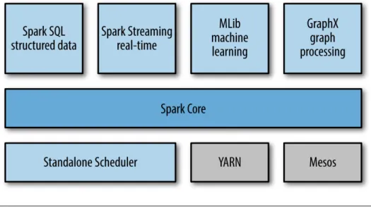
Apache Spark [52] is a fast and general-purpose large-scale data processing engine that
supports general execution graphs, and that can run on top of Hadoop, Mesos, standalone
2.2. Workflow Frameworks
19
or in the cloud (see Figure 2.17). It extends the MapReduce programming model to
effi-ciently support other types of computations (such as batch applications, interactive
algo-rithms, SQL queries or streaming) and by allowing in-memory processing. These features
make easy and inexpensive for users to combine different workloads and define complex
pipelines. Moreover, it has been designed to be highly accessible, providing a simple API in
Java, Scala [17], Python, R and SQL, and supporting a rich set of high-level tools including
Spark SQL for SQL and structured data processing, MLlib for machine learning, GraphX for
graph processing, and Spark Streaming.
F
IGURE2.17: Spark’s Components
Source: Learning Spark [35]
“At a high level, every Spark application consists of a driver program that runs the user’s main
function and executes various parallel operations on a cluster. The main abstraction Spark provides is
a Resilient Distributed Dataset (RDD), which is a collection of elements partitioned across the nodes
of the cluster that can be operated on in parallel”
[52]. For the RDD creation, Spark relies on its
underlying file system.
Figure 2.18 provides the Wordcount implementation in Java using the Spark API.
Al-though the code can be written in a more compact way, we have kept it unrolled for the sake
of clarity and to be easily mapped to the functions defined by the MapReduce programming
model. Thus, as in the MapReduce example shown before, the functions provided are the
Map and Reduce functions, and the main code is written in a sequential-like way. Notice
that the code becomes significantly more readable than in the previous example and, as
expected, the user does not explicitly define the workflow. In fact, when using Spark to
de-velop an application, the user is unaware of the underlying infrastructure and the workflow
diagram.
We must highlight that Apache Spark is widely used nowadays and it is becoming one
of the most powerful Big Data engines. Although it still relies on the MapReduce
program-ming model (making difficult the implementation of sophisticated algorithms which depend
on the state of the processes running on other nodes), Spark provides an efficient and
com-plete framework that separates the user from the common distributed programming issues
such as data dependency analysis, task scheduling, fault-tolerant mechanisms and workers
communication.
20
Chapter 2. State of the art
1 import java.util.Arrays; import org.apache.spark.SparkConf; 3 import org.apache.spark.api.java.JavaPairRDD; import org.apache.spark.api.java.JavaRDD; 5 import org.apache.spark.api.java.JavaSparkContext; import org.apache.spark.api.java.function.FlatMapFunction; 7 import org.apache.spark.api.java.function.Function2; import org.apache.spark.api.java.function.PairFunction; 9 import scala.Tuple2;11 public class WordCount {
13 private static final FlatMapFunction<String, String> SPLIT_WORDS = new FlatMapFunction<>() {
15 public Iterable<String> call(String s) {
return Arrays.asList(s.split(" "));
17 }
};
19
private static final PairFunction<String, String, Integer> MAP_WORDS
21 = new PairFunction<>() {
public Tuple2<String, Integer> call(String s) {
23 return new Tuple2<String, Integer>(s, 1); }
25 };
27 private static final Function2<Integer, Integer, Integer> REDUCE_WORDS = new Function2<>() {
29 public Integer call(Integer a, Integer b) {
return a + b;
31 }
};
33
public static void main(String[] args) throws Exception {
35 String inputFile = args[0]; String outputFile = args[1];
37 // Create a Java Spark Context
SparkConf conf = new SparkConf().setAppName("wordCount");
39 JavaSparkContext sc = new JavaSparkContext(conf);
// Load input data
41 JavaRDD<String> input = sc.textFile(inputFile);
// Split
43 JavaRDD<String> words = input.flatMap(SPLIT_WORDS);
// Transform into words and count
45 JavaPairRDD<String, Integer> pairs = words.mapToPair(MAP_WORDS); JavaPairRDD<String, Integer> counter = pairs.reduceByKey(REDUCE_WORDS);
47 // Save the word count
counter.saveAsTextFile(outputFile);
49 } }
F
IGURE2.18: Wordcount example in Java using Spark
2.2.2.3
Swift
Swift [53] is a fast and easy scripting language for executing distributed and parallel
applications. The programming language is structured like a Shell script and builds a
data-flow oriented workdata-flow. The Swift programs run many copies of ordinary applications as
soon as their inputs are available. The main advantage is that its workflows can be fast
and easily defined, and can run over any underlying architecture (multicore computers,
clusters, clouds or grids). The users must consider that Swift it is not designed to process
large collections of data but to orchestrate programs that do that processing. In this sense,
it is intended to be a pure Workflow Manager: handling the execution of such programs on
remote sites, staging input and output files from these sites and choosing these sites.
2.2. Workflow Frameworks
21
In opposition to the previous cases, Swift is a programming language itself built on top of
Java. Consequently, it provides data types, mapped data types, mapped functions,
conven-tional expressions, structured data, loops and data flow instructions so that users can define
their workflows (see Figure 2.19). Additionally, Swift uses a configuration file to specify the
underlying infrastructure.
F
IGURE2.19: Swift programming language. Source: Swift [53]
To exemplify how Swift works, Figure 2.20 shows the simulation workflow of the Swift
code shown in Figure 2.21. Notice that the code first defines the two applications that the
workflow will invoke: the simulation and the analysis. For both applications, it also defines
their input and output parameters, and their execution instructions (in both cases, the
ex-ecution is an invocation of a bash script to launch the simulation or the analysis). Next, it
retrieves the workflow arguments and define the intermediate variables needed to execute
the workflow. In a third step, it spawns
nsim
simulations; storing its result into separated
files. Finally, it launches an
analyze
application that uses the output files of all the previously
launched simulations.
22
Chapter 2. State of the art
type file;
2
app (file out, file log)
4
simulation (int sim_steps, int sim_range, int sim_values, file sim_script)
6 {
bash @sim_script "--timesteps" sim_steps "--range" sim_range
8 "--nvalues" sim_values stdout=@out stderr=@log; }
10
app (file out, file log) analyze (file s[], file stat_script)
12 {
bash @stat_script filenames(s) stdout=@out stderr=@log;
14 }
16 int nsim = toInt(arg("nsim", "10")); int steps = toInt(arg("steps", "1"));
18 int range = toInt(arg("range", "100")); int values = toInt(arg("values", "5"));
20
file sims[];
22 file simulate_script <"simulate.sh">; file stats_script <"stats.sh">;
24
foreach i in [0:nsim-1] {
26 file simout <single_file_mapper; file=strcat("output/sim_",i,".out")>; file simlog <single_file_mapper; file=strcat("output/sim_",i,".log")>;
28 (simout,simlog) = simulation(steps,range,values,simulate_script); sims[i] = simout;
30 }
32 file stats_out<"output/average.out">; file stats_log<"output/average.log">;
34 (stats_out, stats_log) = analyze(sims,stats_script);
F
IGURE2.21: Swift simulation code example
We must highlight that Swift builds the workflow considering the data dependencies
between applications and exploits the maximum parallelism between applications. Thus,
users must define the workflow regarding data dependencies between applications but do
not need to build the workflow structure explicitly. Moreover, the applications can be any
type of executable, like a shell does, and do not need to follow any convention (like
MapRe-duce obligates users to define
Map
and
Reduce
functions).
2.2.2.4
COMP Superscalar (COMPSs)
Since this project is based in COMP Superscalar (COMPSs) [19] we have decided to
pro-vide a more in-depth view of it in Chapter 3.
23
Chapter 3
COMPSs overview
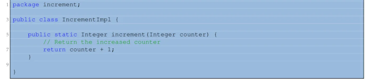
COMP Superscalar (COMPSs) [4] [33] is a task-based programming model that belongs
to the family of Frameworks with implicit workflows. COMPSs applications consist of three
parts: the application’s code developed in a totally sequential manner, an application
inter-face where the programmers specify which functions can be remotely executed (
tasks
) and
a configuration file that describes the underlying infrastructure. With these three
compo-nents, the COMPSs Runtime system exploits the inherent parallelism of the application at
execution time by detecting the task calls and the data dependencies between them.
COMPSs natively supports Java applications but also provides bindings for Python
(Py-COMPSs [23]) and C/C++. Furthermore, (Py-COMPSs allows applications to be executed on
top of different infrastructures (such as multi-core machines, grids, clouds or containers)
without modifying a single line of the application’s code (see Figure 3.1). It also has
fault-tolerant mechanisms for partial failures (with job resubmission and reschedule when task or
resources fail), has a live monitoring tool through a built-in web interface, supports
instru-mentation using the Extrae [8] tool to generate post-mortem traces that can be analysed with
Paraver [15], has an Eclipse IDE, and has pluggable cloud connectors and task schedulers.
F
IGURE3.1: COMPSs overview
Additionally, the COMPSs model has three key characteristics:
•
Sequential Programming:
The users do not need to deal with any parallelization and
distribution issue such as thread creation, synchronization, data distribution,
messag-ing or fault-tolerance. COMPSs programmers only select which methods must be
con-sidered as tasks and the COMPSs Runtime spawns them asynchronously on a set of
resources instead of executing them locally and sequentially.
24
Chapter 3. COMPSs overview
•
Infrastructure Agnostic:
COMPSs model abstracts the application from the
underly-ing infr
![Figure 2.15 shows the implementation of a Wordcount application using the Hadoop [43]](https://thumb-us.123doks.com/thumbv2/123dok_us/503734.2559420/42.892.187.692.430.882/figure-shows-implementation-wordcount-application-using-hadoop.webp)