ISSN: 2040-7467
© Maxwell Scientific Organization, 2011
Received: February 14, 2011 Accepted: March 15, 2011 Published: April 20, 2011
Modelling and Simulation of Closed Loop Controlled Buck Converter
Fed Pmbldc Drive System
1
S. Prakash
and
2R. Dhanasekaran
1
Research Scholar, E.E.E Department, SathyabamaUniveristy, Chennai, Tamilnadu, India
2Syed Ammal Engineering College, Ramanathapuram, Tamilnadu, India
Abstract: Permanent Magnet Brushless DC Motor (PMBLDC) is one of the best electrical drives that has increasing popularity, due to their high efficiency, reliability, good dynamic response and very low maintenance. This makes the interest of modeling an ideal PMBLDC motor and it’s associated Drive System in simple and lucid manner. In this paper the drive system is proposed with a buck converter topology. It has the advantages of reduced switching losses, low inductor power loss, reduced ripple by using a pi-filter, which in turn makes the DC link voltage to be stable. The modeling and simulation of the PMBLDC motor is done using the software package MATLAB/SIMULINK. The operation principle of the buck converter is analyzed and the simulation results are presented in this paper to verify the theoretical analysis.
Key words: Converter, drive, filters, Permanent Magnet Brushless DC Motor (PMBLDC)
INTRODUCTION
Permanent magnet brushless DC (BLDC) motor is increasingly used in automotive, industrial, and household products because of its high efficiency, high torque, ease of control, and lower maintenance (Krishnan, 2003; Krishnan and Shiyoung, 1997). A BLDC motor is designed to utilize the trapezoidal back EMF with square wave currents to generate the constant torque. A conventional BLDC motor drive is generally implemented via a six-switch, three phase inverter (Rahul et al., 2003) and three Hall-effect position sensors that provide six commutation points for each electrical cycle. Cost minimization is the key factor in an especially fractional horse-power BLDC motor drive for Home applications. It is usually achieved by elimination of the drive components such as power switches and sensors. Therefore effective algorithms should be designed for the desired performance and the relevant drive system which in turn controls the motor for all its defined applications with high efficiency, as well as good in maintaining the speed for variable torque. The mathematical modeling of DC to DC converter is given by (Luo, and Ye, 2005; Muo, 2004). The objective of the preset work is to model and simulate buck converter fed PMBLDC drive.
PMBLDC motor: The brushless DC motor is actually a permanent magnet AC motor whose torque-current characteristics mimic the DC motor. Instead of commutating the armature current using brushes,
electronic commutation is used. Having the armature on the stator makes it easy to conduct heat away from the windings, and if desired, having cooling arrangement for the armature windings is much easier as compared to a DC motor. A BLDC is a modified PMSM with the modification being that the back-emf is trapezoidal instead of being sinusoidal as in the case of PMSM (Luk and Lee, 1994). The position of the rotor can be sensed by hall effect position sensors, namely Hall_A, Hall_B, and Hall_C, each having a lag of 120º w.r.t the earlier one. Three Hall position sensors are used to determine the position of the rotor field. Model of a BLDC motor Since a BLDC motor is easy to control, it is the motor of choice in many applications requiring precise control of speed (AtefSalehOthman and Al-Mashakbeh, 2009), (Byoung-KukLee et al., 2001). The BLDC motor model is explained as, the electromagnetic torque, Tem is linearly proportional to the armature current ia. i.e., Tem = KT ia, where KT is the torque constant.
The back-emf in a BLDC motor is linearly proportional to the rotational speed of the shaft. The back-emf is proportional to the speed of the motor and its direction is given by Flemings right hand rule. Considering that in a magnetic field of intensity B, a conductor of length l on the edge of rotor of radius r is rotating at an angular velocity of radians per second. Then the speed of the conductor is given by:
machine is given by Z, and if the number of conductors in series is Z/2, the series back-emf is given by e as:
e = TmrBl (Z/2) In terms of the magnetic flux:
e = KeTm where, KE is the back emf constant.
The model of a BLDC consisting of three phases is explained by means of equations, since there is no neutral used, the sum of the three phase currents must add upto zero, i.e.,
ia+ib+ic = 0 ia+ib = - ic
Considering all the three phases following equations are used to model the two pole three phase BLDC motor.
v
v
v
R
R
R
i
i
i
L
L
L
L
L
L
L
L
L
i
i
i
e
e
e
a b c a b c a b c d dt a ba ca ab b cb ac bc c a b c a b c⎛
⎝
⎜
⎜
⎜
⎞
⎠
⎟
⎟
⎟
=
⎛
⎝
⎜
⎜
⎜
⎞
⎠
⎟
⎟
⎟
⎛
⎝
⎜
⎜
⎜
⎞
⎠
⎟
⎟
⎟
+
⎛
⎝
⎜
⎜
⎜
⎞
⎠
⎟
⎟
⎟
⎛
⎝
⎜
⎜
⎜
⎞
⎠
⎟
⎟
⎟
⎡
⎣
⎢
⎢
⎢
⎤
⎦
⎥
⎥
⎥
+
⎛
⎝
⎜
⎜
⎜
⎞
⎠
⎟
⎟
⎟
0
0
0
0
0
0
If the permanent magnet inducing the rotor field ios in the shape of an arc, it requires that the inductances be independent of the rotor position, hence:
La = Lb = Lc = Lp
Considering the symmetry of the above matrix in addition to independence w.r.t the rotor position:
Lab = Lba = Lbc = Lcb = Lca = Lac = M Above equation reduces to:
Lp
M
M
M
Lp
M
M
M
Lp
i
i
i
e
e
e
d dt a b c a b c⎛
⎝
⎜
⎜
⎜
⎞
⎠
⎟
⎟
⎟
⎛
⎝
⎜
⎜
⎜
⎞
⎠
⎟
⎟
⎟
+
⎛
⎝
⎜
⎜
⎜
⎞
⎠
⎟
⎟
⎟
From above two equations we get:v
v
v
R
R
R
i
i
i
Lp
M
Lp
M
Lp
M
d
dt
i
i
i
e
e
e
a b c a b c a b c a b c a b c⎛
⎝
⎜
⎜
⎜
⎞
⎠
⎟
⎟
⎟
=
⎛
⎝
⎜
⎜
⎜
⎞
⎠
⎟
⎟
⎟
⎛
⎝
⎜
⎜
⎜
⎞
⎠
⎟
⎟
⎟
+
−
−
−
⎛
⎝
⎜
⎜
⎜
⎞
⎠
⎟
⎟
⎟
⎛
⎝
⎜
⎜
⎜
⎞
⎠
⎟
⎟
⎟
⎛
⎝
⎜
⎜
⎜
⎞
⎠
⎟
⎟
⎟
0
0
0
0
0
0
0
0
0
0
0
0
Rearranging the equations, we have obtained equations in a form suitable for simulation. PMBLDC motor with new power converter topology is given by Krishnan and Shiyoung (1997). Four switch three phase brushless motor for low cost commercial applications is given by Lee (2003). The above literature does not deal with Modelling and Simulation of Buck Converter fed PMBLDC drive. This study proposes buck converter for PMBLDC Drive.
SIMULATION RESULTS
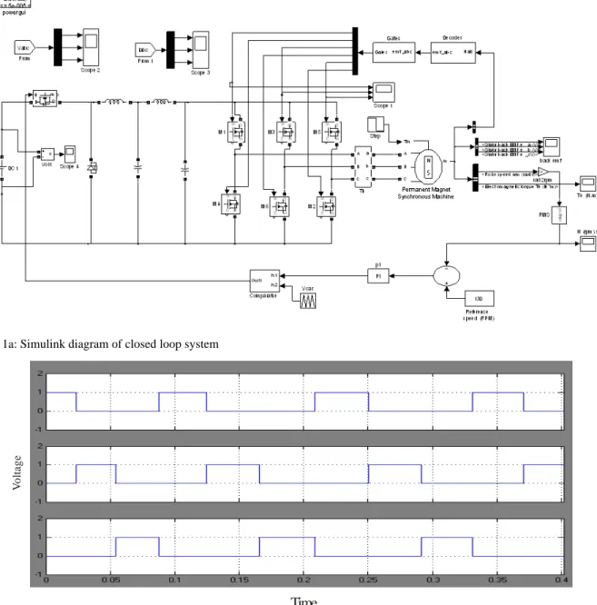
Closed loop system is simulated using Matlab Simulink. The Simulink model of closed loop controlled buck converter inverter fed PMBLDC drive which shown in Fig. 1a. Here 48V DC is stepped down to 24V DC using a buck converter. The output of buck converter is filtered using pi-filter. The output of the pi-filter is applied to the three phase inverter, the inverter produces three phase voltage required by the PMBLDC motor. The technical specifications of the drive systems are as follows:
Input voltage: 48 V DC Buck output voltage: 24 V DC
Pulse width to Buck MOSFET: 0.5 duty cycle (50%) Toff : 50%
Pulse width (33%) to Inverter MOSFET: 120° mode of operation.
Vo
lt
ag
e
Time
Fig. 1a: Simulink diagram of closed loop system
Fig. 1b: Triggering pulses
Parameters of BLDC motor:
The inverter is a MOSFET bridge:
Stator resistance Rs : 2.8750 ohms Stator Inductance Ls : 8.5e-3 Henrys Flux induced by magnets : 0.175 Weber's Back EMF Flat area : 120 degrees
Inertia : 0.8x10G3
Friction factor : 1x10G3
Pole pairs : 4
Stator windings are connected in star to an internal neutral point.
The actual speed is measured and it is compared with the reference speed, the error is given to the PI Controller, the output of the PI controller is one of the inputs to the comparator. The other input is high frequency triangular wave. The output of the comparator controls the pulse width applied to the buck MOSFET. The pulses given to the MOSFETS 1, 3 and 5 are shown in Fig. 1b.
Vo lt ag e
Time
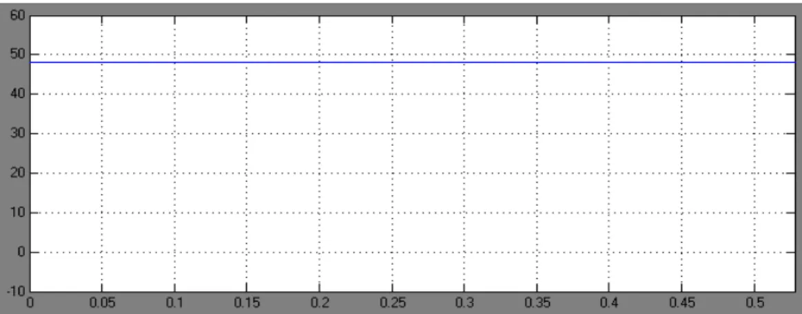
V o lta g e Time C u rr en t Time Fig. 1c: DC input voltageFig. 1d: Phase voltages of inverter
V o lt ag e
Time
S p e e dTime
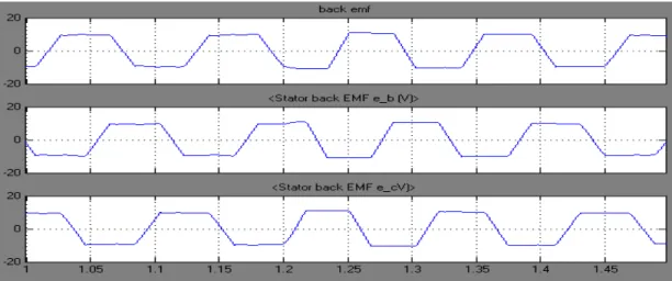
Fig. 1f: Back EMF waveformsFig. 1g: Rotor speed in rpm
D.C. input voltage is shown in Fig. 1c and its value is 48 volts. Phase voltages of the three phase inverter are shown in Fig. 1d. The voltages are displaced by 120º. Three phase currents drawn by the motor are shown in Fig. 1e. The back emfs in the three phases are shown in Fig. 1f. The response of speed is shown in Fig. 1g. The speed settles at 130 rpm, which is equal to the set value. Fig. 1c: DC input voltage
CONCLUSION
Closed loop controlled PMBLDC drive system is modeled and simulated using MATLAB/SIMULINK and the results are presented. Buck converter is proposed to
reduce the input voltage to the required value. Pi-filter is proposed at the output of the buck converter to reduce the ripple. This drive system has advantages like reduced number of switches and improved response. The scope of this paper is modeling and simulation of closed loop controlled PMBLDC drive system. The hardware implementation is yet to be done. The contribution of authors is the development of new simulink model for buck converter fed PMBLDC motor drive.
ACKNOWLEDGMENT
The experiment was conducted in power electronics laboratory, Sathyabama University. The authors would
Atef, S.O. and Al-Mashakbeh, 2009. Proportional Integral and derivative control of brushless DC motor. Eur. J. Sci. Res., 35(2): 198-203.
Byoung-Kuk, L., K. Tae-Hyung and J. Mehrdad Ehsani, 2001. On the feasibility of four-switch three phase BLDC motor drives for low cost commercial applications topology and control. IEEE Tran. Power Electron., APEC, 18(1): 428-433.
Krishnan, R., 2003. A Text Book on Electric Motor Drives, Modelling, Analysis and Control. Prentice Hall of india Pvt Ltd., New Delhi.
Krishnan, R. and L. Shiyoung, 1997. PM brushless DC motor drive with a new power-converter topology. IEEE Tran. Indus. Appl., 33(4): 973-982.
Mathematical modeling for power dc-dc converters. Proc. Inst. Elect. Eng., 152(2): 191-198.
Muo, E.L., 2004. Mathematical modelling for power dc-dc converters. IEEE International Conference. Powercon’04, Singapore, pp: 323-328.
Rahul, K., S.M. Madani, H. Masoud and A.T. Hamid, 2003. A low cost BLDC motor drive using buck-boost converter for residential and commercial Applications. IEEE International Conference on Electric Machines and Drives, IEMDC’03, 2: 1251-1257.