Surviving Wi-Fi Interference in Low Power ZigBee Networks
Chieh-Jan Mike Liang
†, Nissanka Bodhi Priyantha
‡, Jie Liu
‡, Andreas Terzis
††Department of Computer Science ‡Microsoft Research
Johns Hopkins University One Microsoft Way
Baltimore, MD Redmond, WA
{
cliang4, terzis
}
@cs.jhu.edu
{
jie.liu, bodhip
}
@microsoft.com
Abstract
Frequency overlap across wireless networks with differ-ent radio technologies can cause severe interference and re-duce communication reliability. The circumstances are par-ticularly unfavorable for ZigBee networks that share the 2.4 GHz ISM band with WiFi senders capable of 10 to 100 times higher transmission power. Our work first examines the in-terference patterns between ZigBee and WiFi networks at the bit-level granularity. Under certain conditions, ZigBee activities can trigger a nearby WiFi transmitter to back off, in which case the header is often the only part of the Zig-Bee packet being corrupted. We call this the symmetric in-terference regions, in comparison to the asymmetric regions where the ZigBee signal is too weak to be detected by WiFi senders, but WiFi activity can uniformly corrupt any bit in a ZigBee packet. With these observations, we designBuzzBuzz
to mitigate WiFi interference through header and payload
re-dundancy. Multi-Headersprovides header redundancy
giv-ing ZigBee nodes multiple opportunities to detect incom-ing packets. Then, TinyRS, a full-featured Reed Solomon library for resource-constrained devices, helps decoding pol-luted packet payload. On a medium-sized testbed, BuzzBuzz improves the ZigBee network delivery rate by 70%. Further-more, BuzzBuzz reduces ZigBee retransmissions by a factor of three, which increases the WiFi throughput by 10%.
Categories and Subject Descriptors
C.2.1 [Computer-Communications Networks]:
Wire-less Communication
General Terms
Design, Experimentation, Measurement, Performance
Keywords
802.11 Interference Mitigation, 802.15.4, Wireless Mea-surement Study, Error Correction
Permission to make digital or hard copies of all or part of this work for personal or classroom use is granted without fee provided that copies are not made or distributed for profit or commercial advantage and that copies bear this notice and the full citation on the first page. Copyrights for components of this work owned by others than ACM must be honored. Abstracting with credit is premitted. To copy otherwise, to republish, to post on servers or to redistribute to lists, requires prior specific permission and/or a fee.
SenSys’10,November 3–5, 2010, Zurich, Switzerland. Copyright 2010 ACM 978-1-4503-0344-6/10/11 ...$10.00
1
Introduction
We have witnessed over the last ten years a proliferation of wireless technologies that have now become ubiquitous. Given the scarce availability of RF spectrum, many of these technologies are forced to use the same unlicensed frequency bands. For example, IEEE 802.11 (WiFi), IEEE 802.15.1 (Bluetooth) and IEEE 802.15.4 (ZigBee)1all share the same 2.4 GHz ISM band. Cross Technology Interference (CTI)is a consequence of this coexistence that can lead to loss of reliability and inefficient use of the radio spectrum.
The majority of MAC protocols are designed to share the communication medium among nodes that understand the same PHY layer. In this model CTI is considered the same as random background noise, despite the fact that it can cause significant performance degradation. Even worse, system designers have little means to coordinate across net-works that use different wireless standards since they usu-ally belong to different administrative domains. CTI is es-pecially unfavorable for 802.15.4-based wireless sensor net-works that have to counter the effects of severe interference from ubiquitous 802.11 deployments.
We motivate the problem that CTI causes to sensors net-works using our experience from a sensor network
deploy-ment. In this deployment, we placed a network of 90
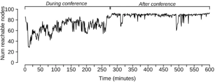
Genomote motes [16] within a 140,000 square feet lecture hall. The motes ran a building energy management applica-tion and used four 15.4 channels simultaneously. 16 Xirrus XN8 WiFi arrays were deployed in the same space. Each WiFi array integrates eight access points, which collectively use all WiFi channels across the entire space. During the Microsoft PDC conference in 2008, 7,000+ people sat in the lecture hall and at the peak time, more than 2,500 people were connected to the WiFi network. Figure 1 shows the number of nodes from the sensor network deployment that successfully reported data over an ten hour period. The WiFi activity during the first four hours completely stressed the
1Technically, the IEEE standards and industrial alliances are dif-ferent. Since this paper primarily considers the PHY and MAC layer interactions among these wireless networks, we make no dis-tinction between WiFi and IEEE 802.11, likewise between ZigBee and IEEE 802.15.4. Furthermore, to shorten the presentation, in the rest of this paper, we will use the terms 802.15.4 and 15.4 inter-changeably. We will also invoke the names of the standard’s differ-ent variants (i.e., 802.11b/g) whenever necessary.
Time (minutes)
Num reachab
le nodes
During conference After conference
0 50 100 150 200 250 300 350 400 450 500 550 600 0 20 40 60 80 100
Figure 1. The number of sensor nodes reporting data over ten hours. Thousands of users were connected to a co-located WiFi network during the first four hours caus-ing dramatic interference to the sensor network.
radio bands and left more than half of the sensor nodes un-reachable.
This result is supported by multiple previous studies that have shown that 15.4 performance significantly degrades in the presence of 802.11 interference [6, 18, 25, 28]. The unan-imous pessimistic conclusion of those studies was that the only way to mitigate such interference is for the 15.4 net-work toavoidthe channels occupied by 802.11.
There are two ways to pursue interference avoidance:
static channel assignmentanddynamic channel assignment (i.e., channel hopping). In a static channel assignment scheme, one assumes that the 802.11 network occupies a fixed number of channels and the 15.4 network is provi-sioned to use frequency bands that are left unused by WiFi. As Figure 2 suggests, this assignment leaves at most two 15.4 channels free from potential 802.11 interference. Further-more, static channel assignment may not work as planned due to node mobility [6] and incremental WiFi deployments. In dynamic channel assignment schemes, different nodes in a sensor network, or the same node over different points in time, will use different 15.4 channels to avoid interfer-ence from nearby WiFi sources. These mechanisms face two challenges: detect the presence of 802.11 traffic [6, 18] and coordinate channel selection among 15.4 senders and re-ceivers [28]. In addition to the coordination complexity, in-terference avoidance mechanisms leave large portions of the spectrum unused even when there is little 802.11 traffic in them. This inefficiency is especially damaging for large and dense sensor networks that cannot support the desired appli-cation throughput using a single 15.4 channel [16, 30].
Instead of trying to avoid interference from 802.11 traf-fic, the goal of this paper is to improve the coexistence of 15.4 and 802.11 networks that operate in the overlapping fre-quency channels. Our approach is based on insights derived from a thorough examination of the interactions between the two radio technologies. In particular, we make several key observations that previous work has overlooked: (1)In the time domain, 802.11 packets are typically much shorter than 15.4 packets, so they cause bursty bit errors in 15.4 packets. (2) A large percentage of dropped 15.4 packets are due to corruptions in the packet headers, especially when the 15.4 transmitter is close to an 802.11 transmitter. (3)We experi-mentally found that when a 15.4 node is close to an 802.11 transmitter, a 15.4 packet can actually cause the 802.11 trans-mitter to back off, due to elevated channel energy. When this
14 2475 2470 2465 2460 2455 2450 2445 2440 2435 2430 2425 2420 2415 2410 2405 2412 2417 2422 2427 2432 2437 2442 2447 2452 2457 2462 2467 2472 2484 Zigbee Channels WiFi Channels 11 12 13 14 15 16 17 18 19 20 21 22 23 24 25 26 1 2 3 4 5 6 7 8 9 10 11 12 13 2480
Figure 2. 802.11b/g and 802.15.4 frequency channels in the 2.4 GHz ISM band. Each 802.11 channel is 22 MHz wide, while 802.15.4 channels are 2 MHz wide.
happens, 802.11onlycorrupts the 15.4 packet header (which causes frequent packet losses), but the remainder of the 15.4 packet is left unaffected.
Depending on how 802.11 and 802.15.4 transmitters in-teract, we partition the interfere domain of the two radios into
symmetric andasymmetricregions. In symmetric regions, a 15.4 transmission can cause nearby 802.11 transmitters to back off, so the receiving bit corruption happens mainly
in 15.4 packet headers. We employ a simple yet
effec-tive header redundancy mechanism, called Multiple-Headers (MH), to address this packet header corruption problem. MH sends the header multiple times in a single 15.4 packet. The first (corrupted) header will cause the 802.11 transmitter to back off, ensuring that the second header can be correctly de-tected by the 15.4 receiver. In asymmetric regions, the 15.4 signal is too weak to affect 802.11 behavior. In this case, we use a forward error correction (FEC) code to correct bit errors that occur across the entire 15.4 packet. We examine Hamming and Reed-Solomon (RS) codes and find that RS code is particularly effective against the bursty error patterns we observed.
We integrate these techniques into theBuzzBuzzprotocol. BuzzBuzz resides at the MAC layer and provides a general-purpose, single hop reliable delivery mechanism that can counter the effects of 802.11 interference. We implemented BuzzBuzz in TinyOS and evaluated its performance on a 57-node testbed under heavy WiFi interference. Specifically, we compare the performance of the Collection Tree Protocol (CTP) [3] with and without BuzzBuzz. The results show that BuzzBuzz improves the packet delivery ratio by 70% and re-duces the number of packet retransmissions by a factor of three. Reducing the number of packet re-transmissions from the sensor network leads to less interference to the WiFi net-work and ultimately higher throughput for 802.11 as well. Thus, BuzzBuzz creates a win-win situation in a crowded spectrum space.
The paper makes the followingcontributions:(1)We are the first to examine and quantify the interference patterns between 802.11 and 802.15.4 networksat a bit-level gran-ularity. (2) We explain how a 802.15.4 node may change the behavior of nearby 802.11 transmitters creating symmet-ric interference between the two radios. Based on these ob-servations, we introduce targeted redundancy mechanisms, namely MH and FEC, that improve 15.4 reception rate. (3) We present a complete implementation of a Reed-Solomon (RS) library suitable for resource-constrained motes. (4)
Payload
Preamble SFD Len CRC
4 1 1 0-125 2
SHR PHR PSDU
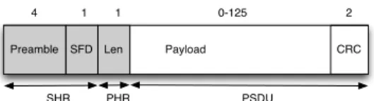
Figure 3. Format of a 15.4 packet. Field sizes are in bytes.
We evaluate a TinyOS implementation of BuzzBuzz through stress tests in a testbed.
The rest of the paper is organized as follows. We provide a brief overview of the WiFi and ZigBee protocols in Sec-tion 2 where we also illustrate the potential for interference between the two radio technologies. Section 3 presents the methodology we used to quantify the interactions between co-located 802.11 and 15.4 networks and an in-depth anal-ysis of the root causes for the observed packet losses. In Section 4 we present techniques for protecting 15.4 packets from 802.11 senders located in the symmetric and asymmet-ric regions, while in Section 5 we describe BuzzBuzz and evaluate its performance on a 57-node TelosB testbed. We present related work in Section 7 and conclude in Section 8.
2
Background
In order to mitigate the impact of cross-technology inter-ference and improve the performance of 802.15.4 networks under 802.11 interference, we need to delve into the details of how these radio technologies interact. We summarize their salient features in the rest of this section.
2.1
802.15.4 Overview
The IEEE 802.15.4 standard defines a PHY layer for low-rate wireless networks operating in the 2.4 GHz ISM band [9]. The standard defines 16 channels within this band, each 2 MHz wide with 3 MHz inter-channel gap-bands (see Figure 2). According to the standard, outgoing bytes are
di-vided into two 4-bit symbols and each symbol is mapped
to one of 16 pseudo-random, 32-chip sequences. The ra-dio encodes these chip sequences using orthogonal quadra-ture phase shift keying (O-QPSK) and transmits them at 2 Mchips/s (i.e., 250 kbps).
Figure 3 shows the format of a 15.4 packet including the Synchronization Header (SHR) and the PHY Header (PHR), shown in grey. The SHR header includes a 4-byte pream-ble sequence (all bytes set to 0x00) and a 1-byte Start of Frame Delimiter (SFD) set to0x7A. The PHR includes a 1-byte Length field that describes the number of 1-bytes in the packet’s payload, including the 2-byte CRC. The maximum packet size is 133 bytes, including all the headers.
The MAC protocol in the 802.15.4 standard defines both
beacon-enabled and non-beacon modes. In the
beacon-less mode, the standard specifies using a CSMA/CA proto-col [9]. While the CSMA/CA protoproto-col uses binary expo-nential backoff, in practice the CSMA/CA protocol imple-mented in TinyOS uses a fixed-length backoff interval [29].
On the receiving side, a 15.4 radio synchronizes to in-coming zero-symbols and searches for the SFD sequence to receive incoming packets. Interference and noise can corrupt the incoming chip stream, leading to 32-chip sequences that do not match one of the 16 valid sequences. The receiver
Time Sender Time Receiver RTS SIFS Data
SIFS SIFS DIFS
CTS ACK
Contention Window
Backoff slots
Frame
Figure 4. Messages and delays defined in the 802.11 MAC protocol. Durations of packet transmissions and time in-tervals depend on the 802.11 variant used. The leading RTS/CTS exchange is used only for large packets.
then maps the input sequence to the valid sequence with the smallest Hamming distance.
We note that some 802.15.4 radios (e.g., CC2420 [26]) provide a user-definedcorrelation thresholdthat controls the maximum Hamming distance between the received 32-chip sequence and the valid SFD sequence that the receiver is willing to tolerate. If this threshold is high, the received signal must closely match the ideal signal, hence the signal-to-noise ratio should be high. If this threshold is low, the receiver allows a low signal-to-noise ratio at the expense of potentially interpreting corrupted packets or channel noise as valid packets.
2.2
802.11 Overview
WiFi networks are almost ubiquitous in office buildings, homes, and even outdoors in urban areas. Considering that 802.11b, 802.11g, and 802.11n share the same 2.4 GHz ISM band with 802.15.4, 802.11 transmissions can interfere with co-located 802.15.4 networks. In the U.S., only 15.4 nels 25 and 26 do not overlap with WiFi and even these chan-nels are covered in other parts of the world. In practice, since most WiFi networks use channels 1, 6, and 11, 15.4 channels 15 and 20 can also be interference-free [16]. The potential for 802.11 transmissions to overwhelm 15.4 receivers is am-plified by the fact that 802.11 radios transmit at 10 to 100 times higher power than 15.4 radios.
Figure 4, which presents the key features of the 802.11 MAC protocol through a timing diagram, helps us under-stand how WiFi nodes use the wireless medium. The 802.11 standard specifies using CSMA/CA with ACKs as the MAC protocol, optionally with the addition of RTS/CTS pack-ets [10]. The protocol also specifies the SIFS and DIFS in-tervals when nodes should defer using the medium.
A time period, called the contention window, follows the DIFS shown in Figure 4. This window is divided into slots. Nodes use a uniform random distribution to select a slot and wait for that slot before attempting to access the medium. The node that selects the earliest slot wins while others defer. Nodes initialize their contention window (CW) to 31 slots and double it every time they fail to access the medium, until CW reaches a maximum size of 1023 slots.
Table 1 summarizes the duration of the DIFS, SIFS, and backoff slots for 802.11b and 802.11g. Also shown are the maximum and minimum packet sizes for 802.11b, 802.11g, and 802.15.4. It is worth noting that for many 802.11b and 802.11g packets, the entire air time is smaller than a 802.15.4 slot time. Based on the relatively small time intervals be-tween 802.11 transmissions, one can easily see that a back-logged 802.11 sender can potentially corrupt the vast
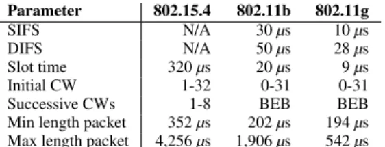
ma-Parameter 802.15.4 802.11b 802.11g
SIFS N/A 30µs 10µs
DIFS N/A 50µs 28µs
Slot time 320µs 20µs 9µs
Initial CW 1-32 0-31 0-31
Successive CWs 1-8 BEB BEB
Min length packet 352µs 202µs 194µs
Max length packet 4,256µs 1,906µs 542µs
Table 1. Packet and interval durations for 802.11 and 802.15.4. The length of the contention windows (CW) for 802.15.4 corresponds to the MAC used by TinyOS. The 802.11 standard uses Binary Exponential Backoff (BEB).
jority of 802.15.4 packets. In the section that follows we experimentally measure the extent of this interference.
3
Measuring WiFi and Zigbee Interactions
We conduct a series of experiments that proceed from quantifying the macroscopic impact of 802.11 interference to 15.4 networks, to exposing the low-level interactions be-tween the two networks that generate the high-level behav-iors we observe. The knowledge of when and how 15.4 pack-ets are corrupted is used to develop a set of compensation techniques that markedly improve the coexistence between the two radio technologies.
3.1
Methodology
Most of the previous work that has examined the in-teraction between 802.11 and 802.15.4 networks has fo-cused on high-level metrics such as packet reception rate (PRR) [4, 23]. In contrast, we examine the interaction be-tween the two radio technologies by accurately detecting and measuring various packet transmission events. Given the packet and interval durations shown in Table 1, this task requires instruments that detect and measure RF events that are as short as a fewµs.
The RFMD ML2724 narrow band radio gives us the abil-ity to detect RF transmissions with the desired timing ac-curacy and precision [22]. The ML2724 can be tuned to a central frequency between 2400 and 2485 MHz and gener-ates an analog voltage on its RSSI OUTpin that is directly proportional to the RF signal energy received in a 2 MHz frequency band centered at the tuned frequency. Given the relative widths of the channels used by 802.11, 15.4, and the ML2724 radio, it is possible to detect 802.11 packets that collide with 15.4 transmissions without being affected by the later transmissions. In practice, we use 15.4 channel 22, 802.11 channel 11, and set the ML2724’s center frequency to 2465.792 MHz (equivalent of 15.4 channel 23).
We selected the ML2724 for two key reasons. First, RSSI measurements are directly available as analog voltage out-puts, which makes it possible to detect RSSI changes quickly by sampling this signal at a high frequency. In contrast, the CC2420 radio exposes the measured RSSI value as the con-tents of an internal register; due to the delays associated with accessing CC2420 registers over the SPI bus, it is impossible to detect most of the 802.11 RF events by reading this RSSI register. The second reason for using the ML2724 is its fast RSSI response. According to the datasheet, the maximum rise and fall times of theRSSI OUTare 4.5 µs and 3µs re-spectively, which make ML2724 an excellent candidate for
detecting the RF activity we are interested in.
While we use the ML2724 radio to detect 802.11 packets, we detect events related to the transmission of 15.4 packets using the GPIO pins of TelosB motes equipped with CC2420 radios [20]. Specifically, we leverage the observation that
the TinyOS event,CaptureSFD.capturedis invoked at the
beginning and the end of 15.4 packet transmissions respec-tively. This event is the interrupt service handler that is triggered when the CC2420 radio toggles its pin at specific points during a radio packet transmission. Under light load, when interrupts are disabled only for short durations, we can accurately detect these CC2420 events by toggling proces-sor GPIO pins from within these TinyOS events. There is however a fixed offset between the actual RF transmissions and the toggling of pins on the CC2420 radio. We measured these offsets by observing theRSSI OUTof a properly tuned ML2724 and the GPIO pin activities of a TelosB mote using an oscilloscope; during these measurements, we also verified that these offsets are constant.
To accurately correlate 802.11 and 802.15.4
transmis-sions over time we connected the RSSI OUT pin of the
ML2724 radio and the mote’s GPIO pins to the same Data Acquisition (DAQ) card that samples and logs analog inputs at 1 MHz frequency [17].
3.2
802.15.4 Packet Reception Ratio
The goal of the first experiments is to quantify at a high level the impact of 802.11 interference on 15.4 links. Con-sidering that lost 15.4 frames must be retransmitted at the cost of increased latency and energy consumption, we adopt packet reception ratio (PRR) as the pertinent metric for this experiment.
Experiment setup. Indoor environments are most likely to house overlapping 802.11 and 15.4 networks and for this rea-son we performed a controlled experiment in the basement of a parking garage. The parking garage had minimal structural obstructions, enabling us to examine the interference under a wide range of inter-node distances. The basement also min-imized the external RF interference on our experiments; a Wi-Spy spectrum analyzer verified that there was very low interference from other RF sources.
The 802.11 network in this experiment consists of an 802.11 b/g access point and a laptop equipped with an 802.11 wireless radio configured in infrastructure mode. This laptop generates a stream of 1,500-byte TCP segments using the
iperftool. To measure the worst-case impact on the 15.4 network, we configureiperfto transmit as quickly as possi-ble. Another laptop, connected to the access point through an Ethernet cable, acts as the traffic sink for the WiFi network. To ensure that our results are not biased by the implementa-tion details of a specific 802.11 chipset, we repeat the exper-iment using multiple access points manufactured by Belkin, Linksys, and Netgear, with Broadcom or Atheros chipsets. All access points produced similar results.
The 802.15.4 network consists of TelosB motes equipped with 802.15.4-compliant TI CC24240 radios [26] running TinyOS 2.1. A dedicated sender sends one max-size packet (i.e., 128 bytes of payload) every 75 ms. These parameters correspond to the sending rate of a high data-rate WSN
ap-802.15.4 Sender 802.15.4 Receivers 802.11 Sender 802.11 Receiver d=15, 65, 115, 170 feet 12 feet 12 feet
Figure 5. Setup for the garage packet reception ratio ex-periment.
plication [16]. The sender’s transmit power is set to 0 dBm and the packets are sent to the broadcast address. We use multiple receivers to minimize any receiver location-specific effects and hardware artifacts. Furthermore, the 802.15.4 re-ceivers are configured to accept packets with CRC errors, while the transmitted packets have a predefined byte pattern to enable off-line bit error analysis for corrupted packets. Each receiver logs the entire packet contents for all incoming packets by transmitting them to a dedicated PC over its se-rial interface. Receivers also record whether a packet passed the CRC check. We use the set up described in Section 3.1 to acquire precise timing of all 802.11 and 802.15.4 packet transmissions. The DAQ card used for timing these transmis-sions is connected to the same PC used to log the 802.15.4 packets.
Figure 5 illustrates the relative positions of all the nodes used in this experiment. We examine the impact of differ-ent levels of 802.11 interference on the packet reception ra-tio (PRR) by varying the distance d between the 802.15.4 and 802.11 nodes. We run four sets of experiments with
d =15,65,115,170 feet. For each value of d, we repeat the experiment using 802.11b and 802.11g radios. During each run, the 15.4 sender broadcasts 2,000 packets; with five 802.15.4 receivers, this corresponds to a total of 10,000 packet receive events under ideal conditions.
Results. We identify three types of 15.4 packet reception events: packets that are received correctly, packets that fail the CRC tests due to corrupted bits, and packets that are lost (i.e., transmitted but never received).
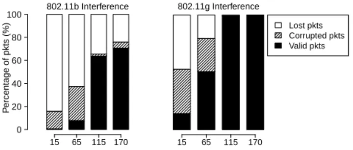
Figure 6 presents the relative percentages for each of these three events for different values ofd. As expected, 802.15.4 PRR is significantly reduced due to 802.11 interference, es-pecially when the two networks are closer to each other. As
dincreases, the 802.15.4 PRR improves since the 802.11 in-terference becomes progressively weaker.
We observe that 802.11b traffic has a much larger impact on the overall 802.15.4 PRR than 802.11g. Thonet et al. made a similar observation and suggested that this difference is due to the higher transmission rate of 802.11g networks, which lowers the channel-time for 802.11 packets [27]. We also observe, especially for smaller separations and 802.11b radios, that the number of lost packets is larger than the num-ber of packets received with bit errors. This observation sug-gests that the front part of a 802.15.4 packet (i.e., the SHR) is more vulnerable to 802.11 interference, especially consid-ering the relative sizes of the different packet parts. The sec-ond observation is important since it indicates that one needs
Distance (ft) P ercentage of pkts (%) 802.11b Interference 0 20 40 60 80 100 15 65 115 170 802.11g Interference Lost pkts Corrupted pkts Valid pkts 15 65 115 170
Figure 6. Percentage of 15.4 packets correctly received, corrupted, and lost as the distance between 802.11 nodes and 15.4 nodes increases.
to focus on improving the detection of (partially) corrupted frames in order to improve the overall PRR. We return to this point in Section 3.4, where we present the distribution of bit errors over a 15.4 packet.
We also found that packet transmission latency increased by as much as 13% to 40% in the presence of 802.11g and 802.11b traffic respectively; another sign of the impact of 802.11 traffic on the 15.4 network. As discussed in Section 2, the 15.4 radio uses a CSMA/CA protocol where it performs a CCA check on the channel prior to each packet transmission. Since the 15.4 radio sends a packet only if the CCA check indicates a free channel, the latency of packet transmissions should increase in the presence of active 802.11 traffic.
Another interesting result is the impact of the 15.4 traffic on 802.11 throughput atd=15 feet. We instrumented the 15.4 sender to transmit 10,000 128-byte packets at a rate of 75 ms, and the packet sniffer, WireShark, running on the 802.11 receiver recorded a 4% drop in TCP throughput.
3.3
Dynamics of 802.15.4 and 802.11
Interac-tion
To better understand the dynamics between the overlap-ping 802.11 and 15.4 networks shown in Figure 5 we exam-ine next the RF activity logs captured during the experiments described in the previous section.
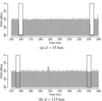
Figure 7 presents a timeline of 802.11b and 15.4 traffic activity when d =15 feet (Figure 7(a)) and d =115 feet (Figure 7(b)). Each vertical box corresponds to a single 15.4 broadcast, while the grey region corresponds to 802.11b ac-tivity, obtained from the narrow band radio as described in Section 3.1.
One can see from Figure 7(a) that 802.11backs-offduring 802.15.4 transmissions, when the separation between 802.11 and 802.15.4 nodes is small — an observation that contra-dicts the common belief that 802.11 nodes do not back off in the presence of 15.4 traffic [21]. We repeated the same experiment with five off-the-shelf 802.11b/g access points (from Apple, Belkin, Linksys, Netgear, and OpenMesh), and all exhibit the same behavior.
This behavior can be attributed to the 802.11 specification that mandates performing a clear channel assessment (CCA) prior to every data packet transmission. In other words, the 802.11b radio in our experiment sensed the channel noise floor being above the CCA threshold and deferred its pend-ing transmission.
Time (ms) RSSI (dBm) 150 160 170 180 190 200 210 220 230 240 −80 −60 −40 −20 0 (a)d=15 feet. Time (ms) RSSI (dBm) 170 180 190 200 210 220 230 240 250 260 −80 −60 −40 −20 0 (b)d=115 feet.
Figure 7. Overlay of 802.11b and 15.4 traffic. Each verti-cal box corresponds to a 15.4 packet transmission, while the gray lines are RSSI measurements corresponding to 802.11 transmissions. Whend is small, the 802.11 radio backs-off when it senses a 15.4 transmission. As d in-creases, the 802.11 radio cannot detect 15.4 transmissions and packets collide.
We also note that in certain cases, the 802.11 radio will not back off. First, the 802.11 specification requires that
RSSI ≥ −70 dBm for the channel to be considered busy
when TX power≤50 mW [10]. Second, the 802.11
specifi-cation lists three CCA modes (i.e., energy detection, packet detection, and both) and vendors can implement one or more at their discretion. 802.11 radios that use the packet detec-tion CCA mode will declare the channel to be clear, since they cannot decode the overheard 15.4 packet transmission.
On the other hand, Figure 7(b) suggests that 802.11 does not back off whend is large. Nevertheless, due to the rela-tively high transmit power of 802.11 radios, the 802.11 trans-missions can interfere with 802.15.4 transmission event at this distance (cf. Figure 6).
The discrepancy between 802.11 and 15.4 transmit pow-ers leads to two distinct interference regions. In the symmet-ric regionthe signal from the 15.4 sender is strong enough to trigger the CCA check on the 802.11 transmitter. On the other hand, in theasymmetric regionthe 802.11 transmitter cannot detect 15.4 packets while it can still corrupt them.
We note that the 802.11 back-off behavior in the sym-metric region seemingly contradicts the packet losses ob-served in Figure 6. Specifically, in the symmetric region, where 802.11 backs off due to ongoing 802.15.4 transmis-sions, we expect to see lower 802.11 interference compared to the asymmetric region. Instead, one can observe in Fig-ure 6 that there is much larger 802.11 induced interference in this region as observed from the large number of lost and corrupted packets. The following sections examine and
ex-Bit position Frequency (%) 0 128 256 384 512 640 768 896 1024 0 5 10 15 20
(a) 802.11b interfering source.
Bit position Frequency (%) 0 128 256 384 512 640 768 896 1024 0 5 10 15 20 (b) 802.11g interfering source.
Figure 8. Bit-error distribution for 15.4 packets that failed the CRC check when the interfering 802.11 trans-mitter is in the symmetric region. It is far more likely that the front part of the 15.4 packet will be corrupted.
plain this apparently contradictory behavior.
3.4
802.15.4 Bit Error Distribution
To resolve the contradiction presented in the previous sec-tion, we examine the distribution of corrupted bits over 15.4 packets that failed the CRC check. Since we know the origi-nal packet content, it is possible to identify the bits that were corrupted during transmission.
First, Figure 8 shows the bit error distribution in the sym-metric region. It is evident that the front section of a 802.15.4 packet has a much higher probability of incurring bit errors compared to the rest of the packet, which has almost zero bit errors. For now, let us sidestep the question why a col-lision happens in the first place and focus on the extent of the collision itself. Considering the relative durations of the 802.11 and 15.4 packets (cf. Table 1), the 802.11 transmis-sion will finish well before the full 15.4 packet has been sent. At this point the 802.11 sender performs a CCA check, notices that the channel is busy, and defers any subsequent (re)transmissions. We note that in Figures 8(a) and 8(b) the extent of the corrupted packet region closely matches the du-ration of a single 1,500-byte 802.11b and 802.11g packet re-spectively.
Figure 9 illustrates this behavior in more detail, provid-ing a zoomed-in view of the event timeline surroundprovid-ing the transmission of a 15.4 packet. It is clear that once the first 802.11 packet collides with the 15.4 packet the 802.11 sender defers any subsequent transmissions until the end of the 15.4 packet. The initial transmission overlap generates the bit errors seen in Figure 8.
The large number of bit errors at the beginning of 15.4 packets can also explain the large number of missing packets as follows. As Figure 3 shows, the front part of the 15.4
Time (ms) RSSI (dBm) 226 228 230 232 234 236 238 −80 −60 −40 −20 0
Figure 9. Detailed view of the 802.11b and 15.4 packet transmission timeline. The overlap at the beginning of the 15.4 packet (vertical box) corresponds to a collision with a 802.11 packet. The 802.11 sender defers sending any additional packets until the 15.4 transmission com-pletes.
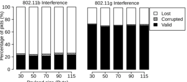
frame includes the SHR and PHR headers. Several problems can occur when the receiver cannot properly decode the SHR and the PHR. First, if the receiver cannot properly decode the Preamble or the SFD field, it will misinterpret the packet as channel noise. Second, if the Length field is corrupted the received packet will be either incomplete (when the decoded length field value is smaller than the actual packet length) or will contain additional junk bits (when the decoded length field value is larger). Both cases will result in a CRC failure. The observation that bit errors are concentrated in the front part of the packet suggests that decreasing the size of the 15.4 packet will not increase the PRR. The results shown in Figure 10 confirm this hypothesis. As before,d=15 feet, but the 15.4 sender broadcasts packets with payload sizes 30, 50, 70, 90, and 115 bytes. Despite a three-fold increase in payload size the PRR remains effectively constant.
We can now explain why 15.4 and 802.11 packets collide. Looking at Figure 4, the only time that a 15.4 sender can be-gin its transmission is during the DIFS + Contention Window period since it otherwise senses the channel as busy. Fur-thermore, the time granularity that the 15.4 sender senses the medium is equal to the slot time (= 320µs) and it senses the medium for eight symbol periods (= 128µs) before declaring the channel as idle [9]. Considering the short length of the DIFS interval and the shorter 802.11 slot time (cf. Table 1) it is very likely that during the time the 15.4 sender senses the channel, the 802.11 node also senses the channel. As a result of both nodes sensing the channel idle, they start transmitting at the same time and subsequently collide.
Finally, Figure 11 shows the 802.15.4 packet bit error dis-tribution in the asymmetric region. Compared to results in the symmetric regions, bit errors are almost uniformly lo-cated throughout the 15.4 packet. We note that the lack of bit errors near the end of the packet in the figure is partly due to the corrupted length field.
The difference in the bit corruption patterns seen in the two regions implies that we need to develop different tech-niques, targeting individual regions, to overcome the nega-tive impact of 802.11 traffic on 15.4 transmissions.
So far we have shown aggregate statistics about which bits in the 15.4 frame are more likely to be corrupted in the two regions. We are also interested in the number of
cor-Payload size (Byte)
P ercentage of pkts (%) 802.11b Interference 0 20 40 60 80 100 30 50 70 90 115 802.11g Interference 30 50 70 90 115 Lost Corrupted Valid
Figure 10. 15.4 packet reception rate as the payload size varies. The competing 802.11 sender lies within the sym-metric region of the 15.4 sender. Since only bits in the front section of the 15.4 packet are corrupted varying the packet’s length does not affect PRR.
Bit position Frequency (%) 0 128 256 384 512 640 768 896 1024 0 1 2 3 4 5
Figure 11. Bit-error distribution for 15.4 packets that failed the CRC check when the interfering 802.11g trans-mitter is in the asymmetric region. Bit errors are evenly distributed across the whole packet.
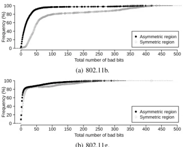
rupted bits and their distribution over individual 15.4 packets since this information will be useful in designing protection mechanisms. Figure 12 presents the CDF of the total num-ber of corrupted bits in both regions for 802.11b and 802.11g senders. Interestingly, corrupted 15.4 packets received in the symmetric region have a wider spread in the number of cor-rupted bits, and they are also more severely damaged than corrupted packets received in the asymmetric region.
While Figure 12 presents the number of corrupted bits, Figure 13 presents the density with which these bits appear over the 15.4 packet. Specifically, it plots the probability density function of the distancenbetween any two corrupted bits in the packet. Small values ofn correspond to bursts of corrupted bits, while corrupted bits randomly scattered throughout the header will result in large values ofn. We can see from this figure that errors occur in bursts, especially in asymmetric regions. This corresponds to, possibly multi-ple, 802.11 packets colliding with the 15.4 packet.
4
Protecting 15.4 packets from WiFi senders
Based on the insights from the above measurements, we design targeted redundancy mechanisms to compensate WiFi interference. Depending on whether the ZigBee node can push back the WiFi transmissions, we investigate techniques for symmetric and asymmetric regions respectively.
4.1
Symmetric Region Techniques
Section 3 shows that in the symmetric region corrupted bits occur at the front of a 15.4 packet. Such corrupted
pack-Total number of bad bits Frequency (%) ●●●●●●●●●●●●●●●●●●●●●●●●●●●●●●●●●●●●●●●●●●●●●●●●●●●●●●●●●●●●●●●●●●●●●●●●●●●●●●●●●●●●●●●●●●●●●●●●●●●●●●●●●●●●●●●●●●●●●●●●●●● ●●●●●●●●●● ●●●●●●●●●●●●●●●●●●●●●●●●●●●●●●●●●●●●●●●●●●●●●●●●●●●●●●●●●●●●●●●●●●●●●●●●●●●●●●●●●●●●●●●●●●●●●●●●●●●●●●●●●●●●●●●●●●●●●●●●●●●●●●●●●●●●●●●●●●●●●●●●●●●●●●●●●●●●●●●●●●●●●● ●● ● ●●● ●● ●● ● ●●● ●●●●●● ●●●●●●●●●●●●●●●●●●●●●●●●●●●●●●●●●●●●●●●●●●●●●●●●●●●●●●●●●●●●●●●●●●●●●●●●●●●●●●●●●●●●● ●●●●●●●●●● ● ●●●● ● ● ●●● ●●●●● ●●●●●●●●●●●●●●●●●●●● ●●●●●●●●●●●●●●●●●●●●●●●●●●●●●●●● ● ● 0 50 100 150 200 250 300 350 400 450 500 0 20 40 60 80 100 ● ● Asymmetric region Symmetric region (a) 802.11b.
Total number of bad bits
Frequency (%) ●● ● ● ● ●● ● ●● ● ●●●●●●●●●●●●●●●●●●●●●●●●●●●●●●●● ●●●●●●●●●●●●●●●●●●●●●●●●●●●●●●●●●●●●●●●●●●●●●●●●●●●●●●●●●●●●●●●●●●●●●●●●●●●●●●●●●●●●●●●●●●●●●●●●●●●●●●●●●●●●●●●●●●●●●●●●●●●●●●●●●●●●●●●●●●●●●●●●●●●●●●●●●●●●●●●●●●●●●●●●●●●●●●●●●●●●●●●●●●●● ●●● ● ● ● ● ● ● ● ●● ● ●●●●●●●●●●●●●●●●●●●●●●●●●●●●●●●●●●●●●●●●●●●●●●●●●●●●●●●●●●●●●●●●●●●●●●●●●●●●●●●●●●●●●●●●●●●●●●●●●●●●●●●●●●●●●●●●●●●●●●●●●●●●●●●●●●●●●●●●●●●●●●●●●●●●●●●●●●●●●●●●●●●●●●●●●●●● ●●●●●●●●● ● ● 0 50 100 150 200 250 300 350 400 450 500 0 20 40 60 80 100 ● ● Asymmetric region Symmetric region (b) 802.11g.
Figure 12. CDF of the number of bad bits in a corrupted packet. n Frequency (%) ●● ●● ●●●●●●●●●●●●●●●●●●●●●●● ●●●●●●●●●●●●●●●●●●●●●●● ● ● ● ●●●●●●●●●●●●●●●●●●●●●●●● ●●●●●●●●●●●●●●●●●●●●●●● 802.11b Interference 0 10 20 30 40 50 60 0 10 20 30 40 50 ● ● ● ●●●●●●●●●●●●●●●●●●●●●●● ●●●●●●●●●●●●●●●●●●●●●● ●● ● ● ● ●●●●●●●●●●●●●●●●●●●●●●●● ●●●●●●●●●●●●●●●●●●●●●●● 802.11g Interference 0 10 20 30 40 50 ● ● Symmetric region Asymmetric region
Figure 13. Distancenbetween any two corrupted bits in a 15.4 packet. Errors caused by competing 802.11b and 802.11g senders occur in concentrated bursts.
ets are traditionally recovered through an Automatic Repeat Request (ARQ) protocol. For example, the Collection Tree Protocol (CTP), a widely used protocol in the WSN commu-nity, uses hop-by-hop retransmissions aggressively [3]. Even though ARQ improves the packet reception ratio, it does so at the expense of higher energy consumption and lower chan-nel throughput.
Considering that only the front section of the packet is corrupted and that a large portion of packets may not be af-fected by interference, retransmitting the same packet multi-ple times is intuitively inefficient. In this section we inves-tigate whether it is possible to overcome this specific form of packet corruption without retransmissions. We start with two straw man approaches that provide the desired outcome only partially and conclude with a simple, yet efficient mech-anism that does.
4.1.1
Correlation Threshold
As we described in Section 2, some 15.4 radios pro-vide a user-definedcorrelation thresholdthat determines the amount of noise that the radio is willing to tolerate when decoding incoming 32-chip sequences in searching for the SHR. Considering that WiFi interference is a form of (non-random) noise, it is then plausible that varying the correla-tion threshold will increase the PRR.
We tested the effectiveness of this technique by varying
Correlation threshold P ercentage of pkts (%) 802.11b Interference 0 20 40 60 80 100 120 12 14 16 18 20 802.11g Interference 12 14 16 18 20 Lost Corrupted Valid Noise pkts
Figure 14. 15.4 PRR in the presence of 802.11b inter-ference as the TI CC2420 correlation threshold varies. Lower threshold values do not increase PRR but lead the receiver to incorrectly decode channel noise as packets.
Preamble length (Byte)
P ercentage of pkts (%) 802.11b Interference 0 20 40 60 80 100 2 5 7 9 11 13 15 802.11g Interference 2 5 7 9 11 13 15 Lost Corrupted Valid
Figure 15. 15.4 PRR as the preamble length varies. Due to the shorter 802.11g packets it is possible to recover all 15.4 frames by increasing the preamble’s length.
the correlation threshold of a CC2420 receiver. In this case, the maximum correlation threshold is 32 and the default is set to 20. While operating in the symmetric region, we var-ied the correlation threshold from 12 to 20 in increments of 2 and logged the received packets. Figure 14 presents the results of this experiment. Decreasing the threshold does not increase the number of correctly received packets. The only change is a negative one: increasing the instances in which the 15.4 radio mistakenly interpreted background or WiFi-related noise as the start of a valid 15.4 packet.
4.1.2
Preamble Length
While the 15.4 specification mandates a 4-byte preamble, radios such as the CC2420 allow the user to set the length of the transmitted preamble up to 17 bytes. We leverage this capability to overcome the effects of 802.11 interference on 15.4 packets as follows. Consider an instance for which the WiFi and 15.4 packets overlap byn15.4 bytes. Then, if the preamble’s length wasn+4 bytes, the receiver would be able to properly decode the preamble’s last four bytes to receive the packet correctly.
To verify that a longer preamble does indeed reduce packet loss in the symmetric region, we ran an experiment in which we varied the preamble length and observed the packet reception ratio. Figure 15 illustrates the experiment’s results. As expected, increasing the preamble length increases the PRR. Nevertheless, this technique has two drawbacks. First, the maximum preamble length that the CC24240 radio sup-ports is 17 bytes. This preamble length cannot fully protect a
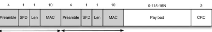
Payload Preamble SFD Len
4 1 1 0-115-16N 2
CRC
Original Header MH Header MAC 10 Preamble SFD Len 4 1 1 MAC 10
Figure 16. MH: a 15.4 packet with an additional header.
15.4 packet from all WiFi packets, since such transmissions can take more than 480µs (cf. Table 1). Second, since the 15.4 specification requires a four-byte preamble, other 15.4 radios, such as the Atmel RF230 [1], do not support variable-length preambles.
4.1.3
Multi-Headers
Next, we introduceMulti-Headers(MH), a light-weight sender-initiated mechanism that emulates the PRR improve-ments due to longer preambles, but is effective against a wider range of competing WiFi packets.
The na¨ıve approach to emulate the effect of longer pream-bles is to send two packets back-to-back. The first packet, whose sole purpose is to save the second packet from cor-ruption, carries a dummy payload to make the 802.11 back off. The following packet can then be correctly received with higher probability. Unfortunately, it can be difficult to trans-mit back-to-back packets. For example, the smallest inter-packet interval with TelosB motes is as high as 600µs,
con-sidering the time to send theSTXONorSTXONCCAcommand
over the SPI bus and the 12 symbol periods that the CC2420 radio waits before each transmission.
Rather than transmitting multiple packets, MH transmits multiple packet headers back to back. Such transmission of consecutive headers is feasible due to the much simpler packet decoding approach that 15.4 radios use, compared to 802.11 radios. Specifically, 802.11 b/g radios use different modulation schemes and transmission rates for the packet header and the payload. This feature allows 802.11 radios to detect and switch to a stronger new packet transmission in the middle of a weaker packet transmission and overcome hidden terminal effects. Furthermore, this approach enables backward-compatibility with older 802.11 standards. On the other hand, 15.4 radios transmit the whole packet with the same modulation scheme and bit rate. Once the 15.4 receiver correctly detects the SHR and PHR headers, it continues to decode the incoming RF signal until it receives the number of bytes mentioned in the PHR header. This feature implies that we can safely add multiple headers within a single 15.4 packet and the receiver will treat them as part of the payload. Figure 16 shows a legitimate 15.4 packet with one addi-tional set of headers in the payload. Given this two header packet structure, if there are no overlapping 802.11 trans-missions, the receiver will detect the first SFD after the first preamble sequence and will treat this SFD as the start of the packet; the radio treats the second packet header as a part of the payload. On the other hand, if the first preamble bytes were corrupted due to an overlapping 802.11 transmission, the 15.4 receiver may not detect the first SFD correctly; in-stead, the receiver will detect the second SFD preceded by four preamble bytes and assume the packet starts at the sec-ond SFD.
With multiple packet headers per packet, the length field
15.4 header Additional headers
1st 2nd 3rd
TCP 30.5% 49.5% 10.0% 1.9%
UDP 28.2% 53.9% 12.9% 1.8%
Table 2. Percentage of packets successfully received using the original 15.4 header or one of the additional headers.
of each header must be properly adjusted. For example, in Figure 16, the length field of the second header corresponds to the length of the actual payload, while the length field of the first header is higher by 16 bytes. Given that the radio treats additional headers as payload, the receiver’s software stack needs to remove any remaining headers from the pay-load before delivering the packet to the user application.
The CRC in the 15.4 packets covers both the header and payload, which limits its applicability in the presence of MH. Specifically, depending on the header detected by the radio, the 15.4 header and payload will be different. To address this problem, we disable the 15.4 CRC filtering on the radio and modify the radio software stack to include a 2-byte CRC within the packet’s payload. This CRC covers the innermost header (excluding the length field) and the user payload. Evaluation. We evaluated the effectiveness of MH using the following experimental setup. Five 802.11g clients were connected to the same AP in infrastructure mode to simulate a typical office setting. These 802.11g clients sent TCP and UDP traffic as fast as possible to the PC connected to the AP via an Ethernet cable. The 802.11g clients were distributed within the same office and the 15.4 sender was 15 ft away from four 15.4 receivers. Activity traces of the 802.11g ac-tivity collected by the ML2724 radio verified that the 15.4 sender was within the symmetric region. The 15.4 sender broadcasted 2,000 128-byte packets at a rate of one packet per 75 ms and it filled the packets payloads with four addi-tional in-payload headers and a 50-byte application payload. In addition, for each header, we replaced the source address field in the 15.4 header with a counter that acts as a header index for offline analysis.
Table 2 shows the number of successfully received pack-ets as triggered by each additional header. Having even a single additional header increases PRR by 50%. The ben-efit of MH diminishes as we increased the number of addi-tional headers beyond one, suggesting that two headers in total are sufficient. Achieving an effective PRR of 80% to 82.1% (compared to the original 28%-30%) outweighs the 20% packet overhead incurred by the one additional header. Finally, we note that we observed similar performance for 802.11b traffic.
4.2
Asymmetric Region Techniques
The results in Section 3 showed thatsymmetricand asym-metricregions lead to two distinct bit error patterns. Bit er-rors in the asymmetric region, in contrast to the symmetric region, are uniformly distributed across the packet. There-fore, MH, that protects only the packet header cannot protect from these bit errors.
Packet loss due to bit errors is resolved using either ARQ or Forward Error Correction (FEC). Although packet retrans-mission is commonly used under low to moderate packet
loss, FEC is more suitable to overcome packet loss under heavy interference for the following reason. Under heavy interference, a packet has to be retransmitted many times, which induces extra energy cost for the motes and increases channel congestion.
FEC augments each packet with extra information that enables the receiver to correct some of the bit errors. Al-though FEC algorithms are widely used in digital commu-nications, selecting the right algorithm and implementing it on resource-constrained sensor nodes are non-trivial. In this section we evaluate several FEC techniques, in terms of their error recovery performance and implementation overhead.
4.2.1
Error-Correction Codes
An FEC transmitter applies an Error-Correction Code (ECC) to the data to be transmitted. The ECC transforms the message to a larger encoded message. The receiver then ap-plies the reverse transformation to recover the original mes-sage from the encoded mesmes-sage. The redundancy in the en-coded message allows the receiver to recover the original message in the presence of a limited number of bit errors.
One example of an ECC is the linear code that the 15.4 physical layer employs to overcome RF noise [9]. As men-tioned in Section 2.1, the 15.4 radio maps 4-bit symbols to 32-bit chip sequences. Since the minimum Hamming dis-tance among the sixteen predefined chip sequences is 12, if the received chip sequence does not have bit errors at more than 6 positions, the 15.4 radio can properly map it to the cor-rect chip sequence. However, we argue that the 15.4 ECC is not sufficient against external 802.11 noise, which typically lasts longer than six chip times, or 3µs.
Next, we evaluate two ECCs, namely the Hamming code and the Reed-Solomon code for correcting 802.11-induced bit errors on 802.15.4 packets.
4.2.2
Hamming Code
Hamming codes enable FEC by adding extra parity bits to the message. They can detect up to two bit errors and correct one bit error in the encoded message. In particular, we use the Hamming(12,8) code, in which four parity bits are added to every eight bits of data to generate encoded messages that are 12 bits long. The Hamming(12,8) code can detect and correct one bit error within the 12 bit word. If more than one bit errors are present, the decoded message will most likely correspond to a data word other than the original. This implies that, once a message with unknown number of bit errors is decoded, the validity of the decoded message has to be verified by some other techniques such as a CRC check.
We implemente a Hamming(12,8) code-based FEC to re-cover 802.11-induced 802.15.4 packet errors. Our imple-mentation uses 72-byte messages, which results in 108-byte encoded messages (we packed two 12-bit encoded values to three bytes). The 72-byte message contains a 2-byte CRC field to verify the messages correctness after the Hamming decoding. This implementation uses 754 bytes of ROM (ex-cluding the CRC code) and 82 bytes of RAM (ex(ex-cluding the data and encoded message buffers). Encoding and decoding the 108-byte messages requires 1.4 ms and 1.8 ms respec-tively on a TelosB mote running at 4 MHz.
Our implementation places each 12-bit encoded message in consecutive locations in the 108-byte packet payload.
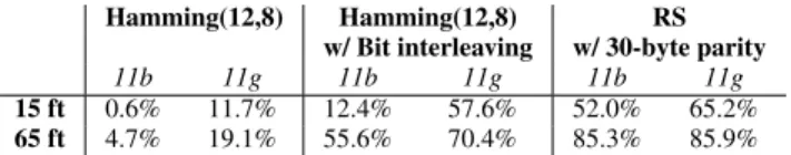
Hamming(12,8) Hamming(12,8) RS w/ Bit interleaving w/ 30-byte parity
11b 11g 11b 11g 11b 11g
15 ft 0.6% 11.7% 12.4% 57.6% 52.0% 65.2%
65 ft 4.7% 19.1% 55.6% 70.4% 85.3% 85.9% Table 3. Percentage of corrupted packet payloads that can be recovered by two version of the Hamming code and the RS code.
Encoding Decoding
15-byte error 30-byte erasure no errors
36.156 ms 181.892 ms 207.824 ms 104.296 ms
Table 4. Execution time for TinyRS operations. The orig-inal message is 65 bytes long and the RS-encoded mes-sage contains the original 65-byte mesmes-sage and the 30-byte parity.
Hence, all the 12 encoded bits are transmitted as consec-utive bits in the radio packet. While the Hamming(12,8) code is very efficient in terms of execution cost and mem-ory overhead, the first column of Table 3 shows that only a very small fraction of the corrupted messages are recovered by the Hamming(12,8)-based FEC scheme. Its poor perfor-mance is due to the burstiness of bit errors (see Figure 13), which results in more than one bit error within an encoded message thus preventing correct error recovery.
Next, we apply bit interleaving to make the encoded mes-sage more resilient to bursty errors. Our implementation
treats the 108-byte encoded messages as a (108 × 8)
se-quence of bits. For each 12-bit encoded message, we evenly spread each bit over the entire message (i.e., two consecutive bits in the 12-bit message are separated by 72 bits in the inter-leaved message). Interleaving is reversed during the decod-ing process by concatenatdecod-ing 12 bits, evenly spread across the message, to form the 12-bit encoded message.
The second column of Table 3 shows the error recovery performance of the bit interleaved Hamming encoding. Due to the heavy use of the bit-level operations, the execution times for encoding and decoding a 108-byte message now become 6.7 ms and 9.2 ms respectively. The implementation consumes 1.4 KB of ROM and 0.1 KB of RAM space.
4.2.3
Reed-Solomon Code
The Reed-Solomon (RS) code is a block-based linear error-correction code with a wide range of applications in digital communications and storage. Unlike the Hamming code, the RS code can recover from both data corruptions and erasures; the former refers to bit flipping atunknown po-sitions in the packet, while the latter refers to missing pieces of data atknownlocations. The RS code divides a message intoxblocks of user-defined size and computes a parity ofy
blocks. An RS-encoded message then consists of the original message and the computed parity. The length of the parity determines the maximum number of corrupted and erasure blocks in the encoded message that the receiver can success-fully recover from. Specifically, foryblocks of parity, the number of erasure and corrupted blocks that the RS code can recover from is:
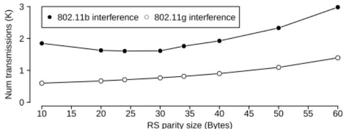
RS parity size (Bytes) Num tr ansmissions (K) ● ● ● ● ● ● ● ● ● ● ● ● ● ● ● ● 10 15 20 25 30 35 40 45 50 55 60 0 1 2 3 ● 802.11b interference● 802.11g interference
Figure 17. Total number of 15.4 transmissions necessary to transfer a 38-KB object over a single hop in the pres-ence of interferpres-ence from 802.11 traffic.
The RS code is commonly (mis-)believed to be too com-putationally and memory intensive for resource-constrained motes [13]. Previous work minimizes the implementation complexity by either implementing only the encoding en-gine [24], or focusing on recovering from data erasures only [14]. However, since a corrupted length field can mis-lead the radio into demodulating a smaller packet, we ar-gue that it is advantageous to handle both data corruptions and erasures. To this end, we have developed a full-featured TinyOS-compatible RS library, TinyRS, based on the work of Karn et al. [19]. The rest of this section outlines the per-formance of RS code based on our TinyRS implementation.
TinyRS has a relatively small code footprint, requiring 2.9 KB of ROM and 1.4 KB of RAM when using 8-bit block size and 30-byte parity. Table 4 presents the micro-benchmark on the execution time in the case of a 65-byte message. The encoding time is significantly lower than the decoding time and the latter also depends on the state of the received RS-encoded message. In Section 5, we further describe a real-world system that attempts to reduce the impact of decoding overhead on network throughput.
The third column of Table 3 illustrates the benefits as-sociated with the increasing processing overhead: RS can successfully recover four times more packets than Ham-ming(12,8) with bit interleaving, when 15.4 packets are cor-rupted by an 802.11b transmitter in the symmetric region.
Using larger parities increases the probability of recov-ering bits corrupted by interference, thereby decreasing the need for retransmissions. At the same time, larger parity creases the space in the 15.4 payload that can be used to de-liver application data, leading to more packet transmissions. To guide the decision on the parity size, we ran simula-tions to determine the expected number of transmissions nec-essary to deliver a 38-KB object over a single hop for various parity sizes. To do so, we first obtained the link’s effective PRR by simulating the transmission of 10,000 RS-encoded packets with various parity sizes and applying the bit errors observed in the packet traces from Figure 6 (68 ft.). We cal-culated the effective PRR for each parity size by counting both valid packets and corrupted packets that RS can suc-cessfully recover. From the effective PRR we calculate the expected number of transmissions to deliver a 38-KB object, shown in Figure 17. The results suggest that the 30-byte par-ity requires the smallest number of transmissions.
Finally, to further illustrate the effectiveness of TinyRS in reducing the expected number of transmissions, we consider
two other packet recovery strategies: packet-level and block-level ARQ. Both approaches rely on acknowledgments to decide whether to initiate retransmissions. However, block-level ARQ divides a packet into sub-blocks and allows the sender to retransmit only the corrupted blocks [5]. For sim-plicity, we assume that the network can always successfully delivery acknowledgement packets. In the scenario of deliv-ering a 38-KB object mentioned before, packet-level ARQ would need to transmit a total of 4,409 packets, while block-level ARQ (with 30-byte blocks) would require a total of 2,313 packets. In comparison, with 30-byte parity, TinyRS transmits only 1,720 packets. However, TinyRS requires ad-ditional energy to encode and decode payload. In the pre-vious example, each RS-encoded packet would use an ad-ditional 0.435 mAs for encoding and decoding packets with 15 or less bit errors on a 4 MHz TelosB mote, or 748 mAs for 1,720 packets. This is in comparison to 1,290 mAs and 284 mAs used by the additional transmissions in packet-level and block-level ARQ (considering both sending data packets and waiting for acknowledgements). If we consider that ac-knowledgements could be lost, we expect the ARQ methods would use even more energy.
5
BuzzBuzz MAC Layer
The results from Sections 4.1 and 4.2 show that MH and TinyRS improve the 802.15.4 PRR in the presence of 802.11 interference. MH improves the detection of packets by pro-tecting the packet header, while TinyRS protects against bit errors in the packet payload. This section presentsBuzzBuzz, a MAC-layer solution that combines MH and TinyRS to im-prove the overall PRR under 802.11 interference. Experi-mental results from a 57-node testbed show that BuzzBuzz improves the end-to-end data yield of the CTP data collec-tion protocol, while reducing the overall network traffic by 71%, under severe 802.11 interference.
5.1
BuzzBuzz Protocol Design
When designing a networking solution, it is important to identify the best architectural layer at which it should oper-ate. We argue that both MH and TinyRS are best positioned at the MAC layer due to the following reasons.
First, the MAC layer typically maintains neighborhood and link quality information that BuzzBuzz can leverage to improve the packet delivery efficiency. For example, de-pending on the link quality, BuzzBuzz can decide if the overhead of running the error correction code is justified. BuzzBuzz can also leverage the MAC layer’s knowledge of the underlying radio header format to construct MH headers. Second, while running FEC only at the source and the destination nodes of a multi-hop path reduces the computa-tion cost, the bit errors accumulated over the intermediate hops will reduce the likelihood of successfully decoding the packet at the destination. Therefore, we optimize FEC oper-ations for the MAC layer and perform packet encoding and decoding on every hop along the end-to-end path.
ARQ is the most widely used approach in WSNs to im-plement reliable delivery at the MAC layer. In ARQ, the sender retransmits a packet if the receiver has explicitly (i.e., negative acknowledgement) or implicitly (i.e., the lack of acknowledgement) indicated that the current packet is lost.
BuzzBuzz complements ARQ with the selective use of MH and TinyRS. The three techniques (i.e., MH , TinyRS, and ARQ) present different trade offs. Although ARQ has the least space and computational overhead, it is not efficient in very noisy environments. Similarly, MH has less com-putational overhead than TinyRS, but is less effective in the asymmetric region. The main challenge that BuzzBuzz ad-dresses is deciding which of these techniques is appropriate given the current link quality.
One can use RSSI samples, collected over a period of time, to detect external channel interference. Mus˘aloiu-E. et al. proposed three aggregation functions to analyze RSSI measurements in real time and detect noisy 15.4 chan-nels [18]. Since interference levels and channel conditions change over time, motes need to periodically sample the channel in that approach. Periodic sampling of RSSI may not be suitable for all the systems, especially those that use low-power duty-cycling.
Instead of periodic sampling, BuzzBuzz infers the chan-nel quality by observing the packet losses, or the lack of packet acknowledgments. Upon receiving a packet from the upper layer, the BuzzBuzz sender first attempts to deliver the packet using ARQ. If the packet cannot be successfully de-livered after three attempts, the BuzzBuzz sender adds the FEC information, and inserts one MH header in the packet. The sender then makes three more transmission attempts of the encoded message before giving up. We note that the BuzzBuzz sender explicitly indicates that a packet contains the FEC parity by setting the reserved bit 7 in the Frame Con-trol Field (FCF) of the 15.4 frame to 1. In addition, to help the receiver locate the application payload, the reserved bit 8 in the FCF of the last MH header is set to 1.
The two-phase retransmission approach has the advantage of avoiding the overhead of MH and TinyRS when exter-nal interference is low. On the other hand, in environments with persistent interference, performing the two-phase prob-ing for each packet slows down the transmission as the initial ARQ phase will most likely fail. To address this problem, BuzzBuzz remembers the setting of the last packet transmis-sion for 60 seconds and applies it to the next packet trans-fer. The sender falls back to the naive retransmission scheme after receiving three consecutive packets that pass the MH CRC. The receiver piggy-backs this information in its ac-knowledgments.
The results from Section 4.2 show that TinyRS requires at least 150 ms to decode a 95-byte RS-encoded packet. This decoding time dominates the processing delay during packet reception. This computational overhead is incurred even when the RS-encoded packet does not have any bit er-rors. BuzzBuzz uses the CRC field of the packet (cf. Sec-tion 4.2) to reduce the decoding overhead when the packet is received with no bit errors. Specifically, BuzzBuzz uses CRC to check the integrity of the payload, and attempts de-coding only if the CRC check fails. CRC can be efficiently implemented with lookup tables, and computing CRC over 65-byte application payload takes approximately 325µs.
5.2
Evaluation
To evaluate BuzzBuzz, we integrated it with the
PacketLink component in TinyOS 2.1. As mentioned in
CTP CTP
w/ BuzzBuzz Packet Delivery Rate 43.05% 73.90%
Avg number pkts/s in the network 38 11
% pkts not ACKed 66% 35%
% pkts received due to MH hdr N/A 10.58%
% corrupted pkts recovered with RS N/A 42.69%
% decrease in 802.11g throughput 14.51% 3.35% Table 5. Summary of experiment results running CTP with BuzzBuzz on a 57-node testbed.
Section 2.1, the CSMA/CA protocol implemented in TinyOS uses a fixed-length backoff interval. We ran experiments on a 57-node TelosB testbed deployed in an office building. All nodes were tuned to 15.4 channel 16. We decided to use a real testbed, because simulators such as TOSSIM do not fully simulate the 15.4 modulation/demodulation scheme and can not match the full realism of testbeds.
Since data collection applications dominate real-world WSN deployments, we developed a simple application that uses the Collection Tree Protocol (CTP) [3] to deliver 65-byte application data from each node at a rate of one packet per minute. CTP relies on acknowledgments and packet re-transmissions to improve the packet delivery rate.
The 802.11 interference originated from a co-located 802.11g testbed on the same building floor. The 802.11g testbed backbone consisted of six OpenMesh OM1P mesh routers forming an ad-hoc mesh backbone on 802.11 channel 5, with one node acting as the gateway between the 802.11 mesh and an Ethernet network. Three Nokia N800 Inter-net tablets used the OpenMesh Inter-network to continuously send TCP traffic to a PC on the same Ethernet network as the OpenMesh gateway.
To ensure that CTP had sufficient time to build its routing tree, we started the 802.11g traffic 20 minutes after the start of the 15.4 nodes. Each experiment lasted two hours. We evaluate the effectiveness of BuzzBuzz using the end-to-end CTP data delivery ratio (or goodput), and the amount of 15.4 network traffic.
Table 5 presents the average results from two experiment runs. CTP with BuzzBuzz is able to deliver 71% more pack-ets while reducing the network traffic by two third. Note that since all data packets carry a 65-byte application payload, the packet delivery rate can be translated into effective data delivery rate. The difference in the amount of network traffic is due to the aggressive retransmissions that CTP uses for un-acknowledged packets. Specifically, a CTP node can attempt up to 30 retransmissions before discarding the packet. Since the probability of packets having at least one bit corruption is high in the presence of 802.11g traffic, many retransmissions are needed for a successful packet delivery. The effective-ness of BuzzBuzz is also evident from the fact that it reduces the number of packets not acknowledged by 50%.
The middle part of Table 5 presents the contributions from each of the two BuzzBuzz components. Approximately 10% of all packets received (valid or corrupted) were due to the MH header being detected by the radio. With a 30-byte par-ity, TinyRS was able to successfully recover approximately 42% of the corrupted packets. Finally, Table 5 shows that