Cable Data Services
DOCSIS® Provisioning of EPON Specifications
DPoE™ Security and Certificate Specification
DPoE-SP-SECv2.0-I02-130808
ISSUED
Notice
This DPoE specification is the result of a cooperative effort undertaken by certain member companies of Cable Television Laboratories, Inc. for the benefit of the cable industry and its customers. This document may contain references to other documents not owned or controlled by CableLabs®. Use and understanding of this document may require access to such other documents. Designing, manufacturing, distributing, using, selling, or servicing products, or providing services, based on this document may require intellectual property licenses from third parties for technology referenced in this document.
Neither CableLabs nor any member company is responsible to any party for any liability of any nature whatsoever resulting from or arising out of use or reliance upon this document, or any document referenced herein. This document is furnished on an "AS IS" basis and neither CableLabs nor its members provides any representation or warranty, express or implied, regarding the accuracy, completeness, noninfringement, or fitness for a particular purpose of this document, or any document referenced herein
DISCLAIMER
This document is published by Cable Television Laboratories, Inc. (“CableLabs®”).
CableLabs reserves the right to revise this document for any reason including, but not limited to, changes
in laws, regulations, or standards promulgated by various agencies; technological advances; or changes in
equipment design, manufacturing techniques, or operating procedures described, or referred to, herein.
CableLabs makes no representation or warranty, express or implied, with respect to the completeness,
accuracy, or utility of the document or any information or opinion contained in the report. Any use or
reliance on the information or opinion is at the risk of the user, and CableLabs shall not be liable for any
damage or injury incurred by any person arising out of the completeness, accuracy, or utility of any
information or opinion contained in the document.
This document is not to be construed to suggest that any affiliated company modify or change any of its
products or procedures, nor does this document represent a commitment by CableLabs or any cable
member to purchase any product whether or not it meets the described characteristics. Nothing contained
herein shall be construed to confer any license or right to any intellectual property, whether or not the use
of any information herein necessarily utilizes such intellectual property. This document is not to be
construed as an endorsement of any product or company or as the adoption or promulgation of any
guidelines, standards, or recommendations.
Document Status Sheet
Document Control Number: DPoE-SP-SECv2.0-I02-130808Document Title: DPoE™ Security and Certificate Specification
Revision History: I01 - Released 10/04/12 I02 - Released 08/08/13
Date: August 8, 2013
Status: Work in Progress
Draft Issued Closed
Distribution Restrictions: Author Only
CL/Member CL/ Member/ Vendor
Public
Key to Document Status Codes
Work in Progress An incomplete document, designed to guide discussion and generate feedback that may include several alternative requirements for consideration.
Draft A document in specification format considered largely complete, but lacking review by Members and vendors. Drafts are susceptible to substantial change during the review process.
Issued A stable document, which has undergone rigorous member and vendor review and is suitable for product design and development, cross-vendor interoperability, and for certification testing.
Closed A static document, reviewed, tested, validated, and closed to further engineering change requests to the specification through CableLabs.
Trademarks
CableLabs® is a registered trademark of Cable Television Laboratories, Inc. Other CableLabs marks are listed at http://www.cablelabs.com/certqual/trademarks. All other marks are the property of their respective owners.
Contents
1 INTRODUCTION ... 1
1.1 DPoE Technology Introduction ... 1
1.2 Scope ... 2
1.3 Goals ... 2
1.4 Requirements ... 2
1.5 DPoE Version 2.0 Specifications ... 3
1.6 Reference Architecture ... 4
1.7 DPoE Interfaces and Reference Points ... 5
2 REFERENCES ... 8
2.1 Normative References... 8
2.2 Informative References ... 9
2.3 Reference Acquisition... 9
3 TERMS AND DEFINITIONS ... 11
3.1 DPoE Network Elements ... 11
3.2 Other Terms ... 13
4 ABBREVIATIONS AND ACRONYMS ... 14
5 OVERVIEW... 16
5.1 Subscriber Data Privacy... 16
5.1.1 Traffic encryption ... 16
5.1.2 Key Exchange ... 17
5.1.3 DPoE ONU Device Authentication ... 17
5.1.4 Early Authentication and Encryption ... 17
5.1.5 Configuration File Security Control ... 17
5.2 Service Provider Network Security ... 18
5.2.1 Control Message Encryption ... 18
5.2.2 IP Denial of Service attack mitigation ... 18
5.2.3 Ethernet Denial of Services Mitigation: Broadcast MAC forwarding ... 18
5.2.4 Limitation of the MAC address learning capacity ... 19
5.2.5 MAC address binding ... 19
5.2.6 Source Address Verification ... 19
5.3 eDOCSIS ... 19
5.4 Secure Software Download ... 19
6 ENCRYPTED FRAME FORMAT ... 20
6.1 1G Downstream-only Cipher Suite (1Down) ... 20
6.2 10G Zero-Overhead Cipher Suite (10Down, 10Bi) ... 20
6.2.1 10G Zero-Overhead Frame Format ... 20
7 KEY MANAGEMENT PROTOCOLS... 22
7.1 1G Downstream-only Key Exchange Protocol ... 22
7.1.1 Set Key Exchange Timer ... 23
7.1.2 Create Key Exchange Timer ... 23
7.1.3 Generate Random Key ... 23
7.1.4 Send Key to DPoE System ... 24
7.1.5 Create Switchover Verification Timer (Optional) ... 24
7.1.6 Switchover Verification Event (Optional for ONU) ... 25
7.1.7 Key Exchange Timer Expiration Event ... 25
7.1.8 Link Deregistration Event ... 25
7.1.10 DPoE OAM Key Exchange Messages ... 28
7.1.11 Summary of 1Down Encryption Parameters ... 28
7.2 10G Downstream-only Key Exchange Protocol ... 28
7.3 10G Bidirectional Key Exchange Protocol ... 28
7.4 1G / 10G Multicast LLID Key Exchange Protocol ... 28
7.4.1 Set Key Exchange Timer ... 29
7.4.2 Generate Random Key ... 29
7.4.3 Send Key to Each D-ONU ... 30
7.4.4 Create Switchover Verification Timer ... 30
7.4.5 Raise/Clear Key Exchange Alarm ... 31
7.4.6 Switch Encryption to New Key ... 31
7.4.7 Link Deregistration Event ... 31
7.4.8 Detecting Key Exchange Failures at the D-ONU (Optional) ... 31
8 AUTHENTICATION AND ENCRYPTION ... 32
8.1 DOCSIS and DPoE Authentication Comparison ... 32
8.2 D-ONU Authentication ... 33
8.2.1 D-ONU MAC Address Identity ... 33
8.2.2 D-ONU Authentication ... 34
8.3 Use of EAP-TLS for D-ONU Authentication ... 34
8.3.1 EAPOL Notes ... 36
8.3.2 EAP Notes ... 37
8.3.3 TLS Notes ... 37
9 SECURE PROVISIONING ... 39
9.1 ONU and CM Management Comparison ... 39
10 USING CRYPTOGRAPHIC KEYS ... 40
10.1 DPoE System ... 40
10.2 D-ONU ... 40
10.3 Authentication of Dynamic Service Requests ... 40
11 CRYPTOGRAPHIC METHODS ... 41
11.1 General encryption requirements ... 41
11.2 DPoE Cipher Suites ... 42
11.2.1 1G downstream-only Cipher Suite (1Down) ... 42
11.2.2 10G Downstream-only Cipher Suite (10Down) ... 42
11.2.3 10G Bidirectional Cipher Suite (10Bi) ... 42
11.3 1 Down Cryptographic Method ... 42
11.3.1 Encrypting Frames ... 42
11.3.2 Decrypting Frames ... 43
11.3.3 Initial Vector (IV) Source ... 43
11.4 10 Down / 10BiCryptographic Method ... 44
11.4.1 Encrypting Frames ... 44
11.4.2 Decrypting Frames ... 45
11.4.3 Initial Vector (IV) Source ... 45
11.4.4 MPCP Jitter Correction ... 45
12 PHYSICAL PROTECTION OF SECURITY DATA IN THE ONU ... 47
13 X.509 CERTIFICATE PROFILE AND MANAGEMENT ... 48
13.1 DPoE-ONU-Certificate Profiles ... 48
13.2 D-ONU Certificate Transport and Verification ... 49
13.3 Code Verification Certificate Profiles ... 50
14.1 Secure File Transfer across the D Interface ... 52
14.2 Secure File Transfer across the TU Interface ... 52
APPENDIX I EXAMPLE FRAMES ... 53
I.1 AES 128 CFB Encrypted Frame ... 53
I.2 D-ONU Certificate Response Frames ... 53
APPENDIX II REFERENCE AES IMPLEMENTATION (C PROGRAMMING LANGUAGE) ... 57
APPENDIX III ACKNOWLEDGMENTS ... 82
APPENDIX IV REVISION HISTORY ... 83
Figures
Figure 1 - DPoE 2.0 Reference Architecture ... 4
Figure 2 - DPoE 2.0 Interfaces and Reference Points... 5
Figure 3 - D-ONU Types ... 12
Figure 4 - DPoE Network Elements ... 12
Figure 5 - Cipher Text Region (1Down) ... 20
Figure 6 - Security Octet (1Down) ... 20
Figure 7 - Cipher Text Region (10Down, 10Bi) ... 20
Figure 8 - Security Octet (10G Zero Overhead) ... 21
Figure 9 - D-ONU Key Exchange State Machine ... 22
Figure 10 - Setting the Key Exchange Timer ... 23
Figure 11 - Send Key to the DPoE System ... 24
Figure 12 - Key Exchange Failure Detected by Link ... 24
Figure 13 - Changing Keys On Timer Expiration ... 26
Figure 14 - Key Exchange Failure Detected By DPoE System ... 27
Figure 15 - Set Key Exchange Timer Failure Detected by DPoE System ... 27
Figure 16 - mLLID Key Exchange DPoE System State Machine ... 29
Figure 17 - Sending mLLID Keys to D-ONUs ... 30
Figure 18 - Authentication in Bidirectional Methods ... 32
Figure 19 - Authentication in Downstream-Only Methods ... 33
Figure 20 - EAP-TLS Message Sequence ... 35
Figure 21 - EAP-TLS Frame Format ... 35
Figure 22 - EAP-TLS Frame Format 2 ... 36
Figure 23 - Encrypting Data with Cipher Feedback Algorithm ... 42
Figure 24 - Decrypting Data with Cipher Feedback Algorithm ... 43
Figure 25 - Determining the Initial Vector ... 43
Figure 26 - Octet Order within the Initial Vector (1G) ... 44
Figure 27 - Encrypting Data with CTR Mode ... 44
Figure 28 - Octet Order within the Initial Vector (10G) ... 45
Tables
Table 1 - DPoEv2.0 Series of Specifications ... 3Table 2 - DPoE Interface and Reference Point Descriptions ... 6
Table 3 - CableLabs Manufacturer Root CA Certificate ... 48
Table 4 - CableLabs DPoE Manufacturer CA Certificate ... 49
Table 5 - CableLabs Code Verification Root CA Certificate ... 50
Table 6 - CableLabs Code Verification CA Certificate ... 50
Table 7 - Manufacturer Code Verification Certificate ... 50
1 INTRODUCTION
DOCSIS Provisioning of EPON (DPoE) version 2.0 specifications are a joint effort of Cable Television
Laboratories (CableLabs), cable operators, vendors, and suppliers to support EPON technology using
existing DOCSIS-based back office systems and processes. DPoEv2.0 specifications augment the DPoE
v1.0 specifications to provide requirements for additional service capabilities and corresponding
provisioning and network management capabilities.
Ethernet PON (EPON) is an [802.3] standard for a passive optical network (PON). A PON is a specific
type of multi-access optical network. A multi-access optical network is an optical fiber based network
technology that permits more than two network elements to transmit and receive on the same fiber.
DPoE specifications are focused on DOCSIS-based provisioning and operations of Internet Protocol (IP)
using DOCSIS Internet service (which is typically referred to as High Speed Data (HSD)), or IP(HSD) for
short, and Metro Ethernet services as described by Metro Ethernet Forum (MEF) standards. DPoE
Networks offer IP(HSD) services, functionally equivalent to DOCSIS networks, where the DPoE System
acts like a DOCSIS CMTS and the DPoE System and DPoE Optical Network Unit (ONU) together act
like a DOCSIS CM.
1.1
DPoE Technology Introduction
DPoE technology was established with the following common requirements already developed by
operators. Each of the participant operators had previously selected 1G-EPON and 10G-EPON as the
appropriate technology for one or more applications. EPON is a widely deployed technology with a
sufficient and large supply of vendors offering a variety of products for each component of the access
network. 10G-EPON technology is available and is backwards compatible with 1G-EPON. A 1G-EPON
network can be incrementally upgraded to 10G-EPON, adding or replacing ONUs as business needs
require. 1G-EPON and 10G-EPON are compatible with [SCTE 174].
1G-EPON and 10G-EPON, originally defined in [802.3ah] and [802.3av] respectively, support a
point-to-multipoint architecture with a centralized controller called an Optical Line Terminal (OLT) and
distributed low cost Layer 2 ONUs. The basic service mapping architecture in EPON is to map Ethernet
(or IP) frame header information (e.g., addresses, IP Differentiated Service Code Points, Ethernet Q tag,
S-VLAN/C-VLAN ID, ISID, bridge address, etc.) to a logical circuit called a Logical Link Identifier
(LLID) in [802.3ah]. The service mapping function in DPoE specifications is similar to that used in
DOCSIS specifications. Both DOCSIS and DPoE networks rely on a centralized scheduler though EPON
utilizes an LLID which functions like a SID in DOCSIS to support unicast, broadcast, and multicast.
Existing [802.3ah] EPON systems do interoperate within the strict definitions of 1G-EPON. Experience
with lab testing, field trials, and deployments has shown operators that 1G-EPON OLT and ONU systems
typically only interoperate with a single port ONU. This is because [802.3ah] specifies the interfaces on
the PON (the DPoE TU interface) but does not specify any of the other system interfaces. For example, an
OLT from vendor A will register an ONU from vendor B, but it is not possible to construct a VLAN
across the DPoE Network. This is a well-recognized limitation of [802.3ah]. The challenge is that neither
1G-EPON nor 10G-EPON specify OAMP to configure the forwarding of traffic between Network to
Network Interface (NNI) ports (I-NNI for MEF or NSI for L2VPN or IP(HSD)) and the PON, or UNI
ports and the PON. This is not different from other Ethernet standards. For example, if two Ethernet
switches from two different vendors are connected, each switch must typically be configured
independently. The challenge for EPON is that the remote device (the ONU) cannot be reached directly,
and therefore cannot be configured. A solution to this problem must then be based on developing a
common (standard) method of reaching the controller for the ONU, identifying the ONU capabilities, and
providing that information to the OLT so that it can configure the ONU to forward traffic.
Even if EPON had solved that provisioning challenge, there are no standard management interfaces for
the ongoing operations and maintenance of the network, including fault management, performance
management, security, etc. Operators already have fully working and scaled-out systems that solve these
challenges for DOCSIS networks. One of the primary goals for DPoE specifications is to use the existing
DOCSIS back office infrastructure to scale up EPON-based business services.
1.2 Scope
This specification identifies recommendations for the adaptation or additions to DOCSIS specifications
that are required to support DOCSIS Provisioning of EPON (DPoE).
Security services may be divided into the following major areas:
•
Subscriber data privacy, includes device authentication and key exchanges to verify that the device
(and accompanying certificates) can insure data path encryption for subscriber data
•
Service provider network security
•
Device software and configuration, including measures used to verify the integrity of the devices,
software on them, and their configurations. Without device security, the other forms of security could
be compromised.
In this document, the term "subscriber" is used synonymously with "customer."
1.3
Goals
The DPoE SEC specification accomplishes the following objectives:
•
Provides a detailed explanation of downstream-only and bi-directional encryption requirements
•
Discusses the protocol and messages used to authenticate the D-ONU and exchange cryptographic
keys
•
Defines requirements for secure software download
•
Describes access control behavior for unauthorized and duplicate MAC addresses
•
Covers IP source address verification requirements.
1.4 Requirements
Throughout this document, the words that are used to define the significance of particular requirements
are capitalized. These words are:
"MUST" This word means that the item is an absolute requirement of this specification. "MUST NOT" This phrase means that the item is an absolute prohibition of this specification.
"SHOULD" This word means that there may exist valid reasons in particular circumstances to ignore this item, but the full implications should be understood and the case carefully weighed before choosing a different course.
"SHOULD NOT" This phrase means that there may exist valid reasons in particular circumstances when the listed behavior is acceptable or even useful, but the full implications should be understood and the case carefully weighed before implementing any behavior described with this label.
"MAY" This word means that this item is truly optional. One vendor may choose to include the item because a particular marketplace requires it or because it enhances the product, for example; another vendor may omit the same item.
1.5
DPoE Version 2.0 Specifications
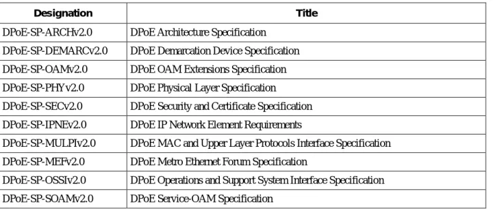
A list of the specifications included in the DPoEv2.0 series is provided in Table 1. For further information
please refer to http://www.cablelabs.com/dpoe/specifications.
Table 1 - DPoEv2.0 Series of Specifications
Designation Title
DPoE-SP-ARCHv2.0 DPoE Architecture Specification
DPoE-SP-DEMARCv2.0 DPoE Demarcation Device Specification
DPoE-SP-OAMv2.0 DPoE OAM Extensions Specification
DPoE-SP-PHYv2.0 DPoE Physical Layer Specification
DPoE-SP-SECv2.0 DPoE Security and Certificate Specification
DPoE-SP-IPNEv2.0 DPoE IP Network Element Requirements
DPoE-SP-MULPIv2.0 DPoE MAC and Upper Layer Protocols Interface Specification
DPoE-SP-MEFv2.0 DPoE Metro Ethernet Forum Specification
DPoE-SP-OSSIv2.0 DPoE Operations and Support System Interface Specification
1.6
Reference Architecture
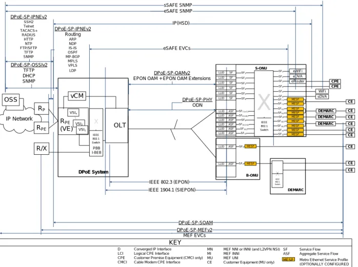
The DPoE reference architecture shown in Figure 1 identifies the elements that a DPoE Network
minimally requires to illustrate and communicate the physical hardware and logical software interfaces
between the functional subsystems of the DPoE architecture. The principal elements in the architecture
are the DPoE System that resides in the headend or hub site, and the DPoE ONU (D-ONU) which may be
an off-the-shelf EPON ONU, EPON SFP-ONU, or an EPON ONU with additional subsystems. The
remaining elements in the architecture are existing servers and systems in the operator's network. All the
server elements have connectivity through an IP (TCP/IP) network. Transport of bearer traffic, and (in
some cases) Layer 2 OAM Protocol Data Units (PDUs) are available through either IP or Layer 2
Ethernet-based Network Interfaces.
DPoE-SP-IPNEv2 Routing ARP NDP IS-IS OSPF MP-BGP MPLS VPLS LDP
X
DPoE System IP Network RPE (VE) DPoE-SP-OSSIv2 TFTP DHCP SNMP DPoE-SP-MEFv2 MEF EVCs DPoE-SP-PHY ODN RPE RP S-ONU B-ONU eDVA IEEE 802.3 (EPON) DPoE-SP-IPNEv2 SSH2 Telnet TACACS+ RADIUS HTTP NTP FTP/SFTP TFTP SNMP OLT DPoE-SP-OAMv2 EPON OAM + EPON OAM ExtensionsR/X OSS DEMARC eRouter IP(HSD) DEMARC eSAFE EVCs X IEEE 802.1 Switch DEMARC sDVA eWiFi WiFi sSAFE SNMP eSAFE SNMP KEY IEEE 1904.1 (SIEPON) MESP MESP MESP MESP MESP MESP ASF MESP MESP MESP DPoE-SP-SOAM vCM LLID ASF LLID SF LLID SF LLID SF LLID SF LLID SF LLID SF LLID D Converged IP Interface LCI Logical CPE Interface
CPE Customer Premise Equipment (CMCI only) CMCI Cable Modem CPE Interface
MN MEF NNI or INNI (and L2VPN NSI) MI MEF INNI
MU MEF UNI
CE Customer Equipment (MU only)
SF Service Flow ASF Aggregate Service Flow
SF1 SF4 SF1 SF2 SF3 SF5 SF6 SF2 SF3 SF4 SF5 SF6 SF7.1 SF7.2 SF8.1 SF8.2 SF9 SF10.1 SF10.2 SF11 SF12 DEMARC ASF LLID SF10.2 ASF LLID SF12 ASF LLID SF10.1+11 ASF LLID SF9 ASF LLID SF8.1+8.2 ASF LLID SF7.1+7.2 SF1 SF2 MESP IEEE 802.1 Switch X IEEE 802.1 Switch PBB I-BEB CE CE CE CE CE CE CE CE CE CPE CPE MESP
MESP Metro Ethernet Service Profile (OPTIONALLY CONFIGURED VSIn
VSI2
VSI1
1.7
DPoE Interfaces and Reference Points
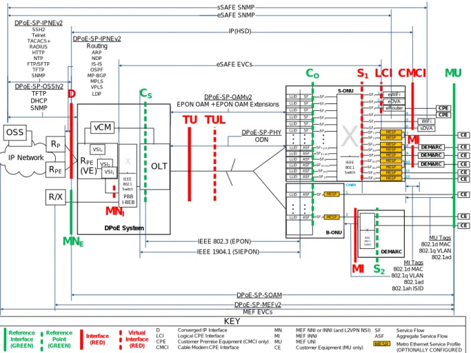
The DPoE interfaces and reference points shown in Figure 2 provide a basis for the description and
enumeration of DPoE specifications for the DPoE architecture. Each interface or reference point indicates
a point between separate subsystems. The reference points have protocols that run across them, or have a
common format of bearer traffic (with no signaling protocol). All the interfaces are bi-directional
interfaces that support two-way communications. The protocols in DPoE specifications operate within
different layers based on the [802.3], [802.1], IETF, MEF, and CableLabs specifications. The C reference
points are uni-directional for upstream (C
O) or downstream (C
S) classification, respectively.
DPoE-SP-IPNEv2 Routing ARP NDP IS-IS OSPF MP-BGP MPLS VPLS LDP
X
MI Tags 802.1d MAC 802.1q VLAN 802.1ad 802.1ah ISID DPoE System IP Network R PE (VE) DPoE-SP-OSSIv2 TFTP DHCP SNMP DPoE-SP-MEFv2 MEF EVCs DPoE-SP-PHY ODN RPE RP S-ONU B-ONU eDVA IEEE 802.3 (EPON)D
TU
DPoE-SP-IPNEv2 SSH2 Telnet TACACS+ RADIUS HTTP NTP FTP/SFTP TFTP SNMP OLT DPoE-SP-OAMv2 EPON OAM + EPON OAM ExtensionsR/X OSS
MN
I DEMARCS
1 eRouter IP(HSD) DEMARC eSAFE EVCs X IEEE 802.1 SwitchLCI
DEMARCMI
C
OC
SCMCI
sDVA eWiFi WiFi sSAFE SNMP eSAFE SNMP KEY Reference Point (GREEN) Interface (RED)MU
IEEE 1904.1 (SIEPON)TUL
Virtual Interface (RED) MESP MESP MESP MESP MESP MESP ASF MESP MESP MESP DPoE-SP-SOAM Reference Interface (GREEN) vCM MU Tags 802.1d MAC 802.1q VLAN 802.1ad LLID ASF LLID SF LLID SF LLID SF LLID SF LLID SF LLID SF LLID D Converged IP Interface LCI Logical CPE InterfaceCPE Customer Premise Equipment (CMCI only) CMCI Cable Modem CPE Interface
MN MEF NNI or INNI (and L2VPN NSI) MI MEF INNI
MU MEF UNI
CE Customer Equipment (MU only)
SF Service Flow ASF Aggregate Service Flow
SF1 SF4 SF1 SF2 SF3 SF5 SF6 SF2 SF3 SF4 SF5 SF6 SF7.1 SF7.2 SF8.1 SF8.2 SF9 SF10.1 SF10.2 SF11 SF12 DEMARC 4 1 2 3 5 6 7 8 9 10 11 12 ASF LLID SF10.2 ASF LLID SF12 ASF LLID SF10.1+11 ASF LLID SF9 ASF LLID SF8.1+8.2 ASF LLID SF7.1+7.2 CMIM 1 2 SF1 SF2 MESP IEEE 802.1 Switch
S
2MN
E X IEEE 802.1 Switch PBB I-BEBMI
CE CE CE CE CE CE CE CE CE CPE CPE MESPMESP Metro Ethernet Service Profile (OPTIONALLY CONFIGURED VSIn
VSI2
VSI1
Table 2 - DPoE Interface and Reference Point Descriptions
Interface or Reference Point
Interface or Reference Point Description
MN MN is a logical concept used for the specification of requirements for MEF INNI that apply to both MNE and MNI. MN logically provides the equivalent function of a MEF INNI or L2VPN NSI. It is an NNI for Metro Ethernet services only.
MNE The MNE (MEF INNI External) interface is a substitute for the MN reference interface from DPoE version 1.0 specifications. The MN interface is an [802.3] interface for Ethernet (or MEF or L2VPN emulated) services only. It serves the role of a MEF INNI or L2VPN NSI. It is an NNI for Metro Ethernet services only.
MNI The MNI reference interface is used to describe the virtual interface between an OLT and a VPLS Virtual Switch Instance (VSI). In particular, it is used to describe the requirements for stitching VSIs to DPoE System and OLT [802.1] components such as [802.1d] bridge groups, [802.1ad] S-VLAN or C-VLAN (S-component or C-component), or [802.1ad] I-BEB (I-component) or B-I-BEB (B-component) backbone edge bridges. The DPoE System stitches VPLS and VPWS transport and forwarding for Metro Ethernet Services between the D interface and the MNI reference interface
1 .
D The D interface is the DOCSIS IP NNI interface. It is an operator network facing interface, sometimes called a Network Systems Interface (NSI) in DOCSIS specifications. The D interface allows a DPoE System to communicate with an IP network. The D interface carries all IP management traffic including OSSI and IP NE traffic. The D interface carries all DOCSIS IP service traffic, IP/MPLS/VPLS traffic, and IP/MPLS/VPWS traffic.
TU The TU interface is a short form of expressing the interface between the DPoE System and the D-ONU.
TUL The TUL interface is a virtual interface representing a logical EPON on an ODN. Each ODN has at least one TUL, and each TUL represents a MAC domain.
C The C reference point is used for explanation of traffic ingress to a DPoE classifier. CO The CO reference point is used for explanation of traffic ingress to a D-ONU upstream
classifier.
CS The CS reference point is used for explanation of traffic ingress to a DPoE System downstream classifier.
S The S interface is an IEEE 802 interface. The S interface may be an internal interface, such as [802.3] across a SERDES (GMII or XGMII) interface in a BP-ONU (such as a SFP-ONU, SFP+ONU or XFP-ONU), or it may be an external Ethernet interface in a BB-ONU or S-ONU.
S1 is an interface for an S-ONU. S2 is a reference point used for explanation of services with the B-ONU.
S1 The S1 interfaces are the general case of all interfaces on an S-ONU. S1 interfaces may be CMCI, LCI, MI, or MU interfaces.
S2 The S2 reference point is used for explanation of traffic ingress to and egress from interfaces on a DEMARC device in a DPoE System. Although there are no specifications or
requirements for the S2 reference point, informative text refers to the S2 reference point to provide the full context for the use of a B-ONU with a DEMARC device providing Metro Ethernet services.
LCI The Logical CPE Interface (LCI) interface is an eDOCSIS interface as defined in [eDOCSIS]. eSAFEs are connected to LCI interfaces.
CMCI CMCI is the DPoE interface equivalent of the DOCSIS Cable Modem CPE Interface as defined in [CMCIv3.0]. This is the service interface for DOCSIS-based IP services. Customer Premise Equipment (CPE) is connected to CMCI interfaces.
1
MNI is required for IP-based forwarding and transport of Metro Ethernet services with DPoE in order to provide MEF E-LAN and E-Tree services described in DPoE version 2.0. While these services can be constructed with MNE, these specifications do not describe the process to do so.
Interface or Reference Point
Interface or Reference Point Description
MI MI is an S interface that operates as a MEF INNI with additional requirements as specified in [DPoE-SP-MEFv2.0]. The MI interface is an [802.3] interface (or reference point) between a D-ONU and a DEMARC device.
• A D-ONU that provides a MEF INNI has an MI interface.
• A D-ONU can have MU as an interface and an MI reference point on different S interfaces in a single D-ONU.
DEMARC devices are connected to MI interfaces.
MU MU is an S interface (or S reference interface) that operates as a MEF UNI. The MU reference interface is an [802.3] interface (or reference point) between a D-ONU or a DEMARC device and a customer's equipment.
• A D-ONU that directly provides a MEF UNI (MU) interface has MU as an interface.
• A D-ONU can have MU as an interface and an MI reference point on different S interfaces in a single D-ONU.
2 REFERENCES
2.1 Normative References
In order to claim compliance with this specification, it is necessary to conform to the following standards
and other works as indicated, in addition to the other requirements of this specification. Notwithstanding,
intellectual property rights may be required to use or implement such normative references. At the time of
publication, the editions indicated were valid. All references are subject to revision, and users of this
document are encouraged to investigate the possibility of applying the most recent editions of the
documents listed below. References are either specific (identified by date of publication, edition number,
version number, etc.) or non-specific. For a non-specific reference, the latest version applies.
[802.1d] IEEE Std 802.1d™-2004, IEEE Standard for Local and Metropolitan Area Networks: Media Access Control (MAC) Bridges
[802.1q] IEEE Std. 802.1q-2009, IEEE Standard for Local and Metropolitan Area Networks-Virtual Bridged Local Area Networks, January 2010.
[802.3av] IEEE Std. 802.3av-2009, Amendment to IEEE Std. 802.3-2008: Physical Layer Specifications and Management Parameters for 10 Gb/s Passive Optical Networks.
[DPoE-SP-ARCHv2.0] DPoE-SP-ARCHv2.0, DOCSIS Provisioning of EPON, DPoE Architecture Specification, Cable Television Laboratories, Inc.
[DPoE-SP-DEMARCv2.0]
DOCSIS Provisioning of EPON, DPoE Demarcation Device Specification, DPoE-SP-DEMARCv2.0, Cable Television Laboratories, Inc.
[DPoE-SP-IPNEv2.0] DPoE-SP-IPNEv2.0, DOCSIS Provisioning of EPON, IP Network Element Requirements, Cable Television Laboratories, Inc.
[DPoE-SP-MEFv2.0] DPoE-SP-MEFv2.0, DOCSIS Provisioning of EPON, Metro Ethernet Forum Specification, Cable Television Laboratories, Inc.
[DPoE-SP-MULPIv2.0] DPoE-SP-MULPIv2.0, DOCSIS Provisioning of EPON, MAC and Upper Layer Protocols Requirements, Cable Television Laboratories, Inc.
[DPoE-SP-OAMv2.0] DPoE-SP-OAMv2.0, DOCSIS Provisioning of EPON, OAM Extensions Specification, Cable Television Laboratories, Inc.
[DPoE-SP-OSSIv2.0] DPoE-SP-OSSIv2.0, DOCSIS Provisioning of EPON, Operations and Support System Interface Specification, Cable Television Laboratories, Inc.
[DPoE-SP-PHYv2.0] DPoE-SP-PHYv2.0, DOCSIS Provisioning of EPON, Physical Layer Specification, Cable Television Laboratories, Inc.
[eDOCSIS] Data-Over-Cable Service Interface Specifications, eDOCSIS Specification, CM-SP-eDOCSIS, Cable Television Laboratories, Inc.
[FIPS-140-2] Federal Information Processing Standards Publication (FIPS PUB) 140-2, Security Requirements for Cryptographic Modules, June 2001.
[NIST 800-108] NIST Special Publication 800-108, Recommendation for Key Derivation Using Pseudorandom Functions, October 2009.
[RFC 1750] IETF RFC 1750, Randomness Recommendations for Security, December 1994.
[RFC 4346] IETF RFC 4346, The Transport Layer Security (TLS) Protocol, Version 1.1, April 2006.
[SECv3.0] Data-Over-Cable Service Interface Specifications, Security Specification, CM-SP-SECv3.0, Cable Television Laboratories, Inc.
2.2
Informative References
This specification uses the following informative references.
[802.1] Refers to entire suite of IEEE 802.1 standards unless otherwise specified.
[802.1ad] IEEE Std. 802.1ad-2005™, IEEE Standard for Local and Metropolitan Area Networks – Virtual Bridged Local Area Networks Amendment 4: Provider Bridges, May 2006. [802.1X] IEEE 802.1X-2010, Port Based Network Access Control.
[802.3] IEEE Std. 802.3-2008, IEEE Standard for Information technology-Telecommunications and information systems-Local and metropolitan area networks-Specific requirements, Part 3: Carrier Sense Multiple Access with Collision Detection (CSMA/CD) access method and Physical Layer specifications.
[802.1ae] IEEE Std 802.1ae-2006, IEEE Standard Medium Access Control (MAC) Security, "Media Access Control (MAC) Security", June 2006.
[802.1ag] IEEE Std 802.1ag™-2007, IEEE Standard for Local and metropolitan Area Networks – Virtual Bridged Local Area Networks Amendment 5: Connectivity Fault Management, December 2007.
[802.3ah] IEEE Std. 802.3ah-2004, Amendment to IEEE Std. 802.3-2003: Media Access Control Parameters, Physical Layers, and Management Parameters for Subscriber Access Networks, now part of [802.3].
[CMCIv3.0] Data-Over-Cable Service Interface Specifications, Cable Modem to Customer Premise Equipment Interface Specification, CM-SP-CMCIv3.0, Cable Television Laboratories, Inc. [DOCSIS] Refers to entire suite of DOCSIS 3.0 specifications unless otherwise specified.
[FIPS-197] Federal Information Processing Standards Publication (FIPS PUB) 197, Advanced Encryption Standard, November, 2001.
[MULPIv3.0] Data-Over-Cable Service Interface Specifications, MAC and Upper Layer Protocols Interface Specification, CM-SP-MULPIv3.0, Cable Television Laboratories, Inc.
[OSSIv3.0] Data-Over-Cable Service Interface Specifications, Operations Support System Interface Specification, CM-SP-OSSIv3.0, Cable Television Laboratories, Inc.
[RFC 3748] IETF RFC 3748, Extensible Authentication Protocol (EAP), June 2004. [RFC 5216] IETF RFC 5216, The EAP-TLS Authentication Protocol, March 2008.
[SCTE 174] ANSI/SCTE 174 2010, Radio Frequency over Glass Fiber-to-the-Home Specification.
2.3 Reference Acquisition
•
Cable Television Laboratories, Inc., 858 Coal Creek Circle, Louisville, CO 80027;
Phone +1-303-661-9100; Fax +1-303-661-9199;
http://www.cablelabs.com
•
FIPS Publications, NIST, 100 Bureau Drive, Gaithersburg, MD 20899-3460; Internet:
http://www.itl.nist.gov/fipspubs/
•
Internet Engineering Task Force (IETF) Secretariat, 48377 Fremont Blvd., Suite 117, Fremont,
California 94538, USA, Phone: +1-510-492-4080, Fax: +1-510-492-4001,
http://www.ietf.org
•
Institute of Electrical and Electronics Engineers (IEEE), +1 800 422 4633 (USA and Canada);
http://www.ieee.org
•
SCTE, Society of Cable Telecommunications Engineers Inc., 140 Philips Road, Exton, PA 19341
Phone: +1-800-542-5040, Fax: +1-610-363-5898, Internet:
http://www.scte.org/
3 TERMS AND DEFINITIONS
3.1 DPoE Network Elements
DPoE Network This term means all the elements of a DPoE implementation, including at least one
DPoE System, one or more D-ONUs connected to that DPoE System, and possibly one or more DEMARCs
DPoE System This term refers to the set of subsystems within the hub site that provides the
functions necessary to meet DPoE specification requirements.
DPoE ONU (D-ONU) This term means a DPoE-capable ONU that complies with all the DPoE
specifications. There are two logical types of D-ONUs. These are the DPoE Standalone ONU (S-ONU) and the DPoE Bridge ONU (B-ONU). Requirements specified for a D-ONU must be met by all ONUs.
DPoE Standalone ONU (S-ONU)
This term means a D-ONU that provides all the functions of a B-ONU and also provides at least one CMCI port. An S-ONU can optionally have one or more eSAFEs.
DPoE Bridge ONU (B-ONU) This term means a D-ONU that is capable of [802.1] forwarding but cannot do all
the encapsulation functions required to be an S-ONU. The B-ONU is a logical definition used by the specification for requirements that apply to all types of B-ONUs. The two types of B-ONUs are the BP-ONU and the BB-ONU.
DPoE Bridge Pluggable ONU (BP-ONU)
This term means a D-ONU that is a B-ONU which is pluggable. Pluggable BP-ONUs include devices such as an SFP-ONU (1G-EPON), SFP+ONU (10G-EPON), or XFP-ONU (10G-EPON).
DPoE Bridge Baseband ONU (BB-ONU)
This term means a D-ONU that is a B-ONU which has a baseband IEEE Ethernet interface. BB-ONUs include those with one or more [802.3] baseband PMDs. (See [DPoE-SP-ARCHv2.0], section 7.2.6.2 for examples.)
DEMARC Short form of "Demarcation Device." This term means the device, owned and
operated by the operator that provides the demarcation (sometimes called the UNI interface) to the customer. Some architectures describe this device as the CPE (as in DOCSIS) or the NID (as in the MEF model).
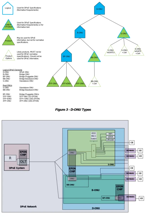
Product Logical D-ONU B-ONU S-ONU SFP-ONU BP-ONU SFP+ONU XFP-ONU S-ONU +eSAFEs S-ONU +.1ah S-ONU +eSAFE +.1ah Product Options
Logical DPoE Elements D-ONU DPoE ONU B-ONU Bridge ONU BP-ONU Bridge Pluggable ONU BB-ONU Bridge Baseband ONU S-ONU Standalone ONU Real ONUs
S-ONU Standalone ONU BB-ONU Bridge Baseband ONU BP-ONU Bridge Pluggable ONUs SFP-ONU SFP ONU (1G-EPON) SFP+ONU SFP+ ONU (10G-EPON) XFP-ONU XFP-ONU (10G-EPON)
Used for DPoE Specifications (Normative Requirements)
May be used for DPoE informative, but not for normative specifications.
Likely products. MUST not be used for DPoE normative (specifications). Should not be used for DPoE informative. Logical
+ Product
Used for DPoE Specifications (Normative Requirements) or for informative text.
BB-ONU
BB-ONU +.1ah
Figure 3 - D-ONU Types
DPoE System R ONU X S-ONU BB-ONU eDVA OLT ONU eRouter DEMARC IEEE 802.1 Switch DEMARC WiFi D-ONU EPON CHIP EPON CHIP ONU BP-ONU DEMARC B-ONU EPON CHIP DPoE Network DEMARC CE CE CE CE CE CE DEMARC CE
3.2
Other Terms
1G-EPON EPON as defined in [802.3ah]
10G-EPON EPON as defined in [802.3ah] and amended in [802.3av]
Cable Modem CPE Interface CMCI as defined in [MULPIv3.0]
Customer Premise Equipment (CPE)
Customer Premise Equipment as defined in [DOCSIS]
Multi-Layer Switching (MLS)
A switch that can switch based on Layer 2, Layer 3, Layer 4, etc.
Ethernet Passive Optical
Network (EPON)
Refers to both 1G-EPON and 10G-EPON collectively
EPON Operations and Maintenance Messaging (OAM)
EPON OAM messaging as defined in [802.3ah] and [DPoE-SP-OAMv2.0]; Ethernet OAM is not the same as EPON OAM; Ethernet OAM is [802.1ag]
Logical CPE Interface LCI as defined in [eDOCSIS]
Network Interface Device (NID)
4 ABBREVIATIONS AND ACRONYMS
This specification uses the following abbreviations:
AES Advanced Encryption Standard
CMCI Cable Modem CPE Interface
CPE Customer Premise Equipment.
DA Destination Address
DEMARC Demarcation Device
DoS Denial of Service
DPoE DOCSIS Provisioning of EPON
EAP Extensible Authentication Protocol
eCM embedded Cable Modem
eDVA embedded Digital Voice Adapter
EPL Ethernet Private Line
EPON Ethernet Passive Optical Network
EVC Ethernet Virtual Connection
IP Internet Protocol
LLID Logical Link Identifier
MEF Metro Ethernet Forum
MEN Metro Ethernet Network
MI MEF INNI Interface at a customer premise
MKA MACSec Key Agreement protocol
MN MEF INNI Interface to operators MEN
MPCP Multi-Point Control Protocol
MPCPDU MPCP Data Unit
MU MEF UNI Interface
ODN Optical Distribution Network
OLT Optical Line Termination
OSC Optical Splitter Combiner
ONU Optical Network Unit
PHY PHYsical Layer
PON Passive optical network
QoS Quality of Service
R IP Router
SA Source Address
SCB Single Copy Broadcast
SSD Secure Software Download
UNI User Network Interface
vCM Virtual Cable Modem
5 OVERVIEW
DPoE security comprises functions within each of the DPoE Network elements and interfaces between
the OSS, DPoE Network elements, and interfaces between the DPoE Network elements and subscriber
devices or networks.
The security architecture is composed of discrete security functions and protocols that individually or
collectively provide security for each of the security areas.
•
Subscriber data privacy (TU interface)
•
Subscriber network security (TU and C interfaces)
•
Service provider network security (TU and C interfaces)
•
Device software and configuration (D, TU, and C interfaces)
Security for the D interface is out of the scope of this specification. Some security functions for the TU
interface rely on communication over the D interface.
Security on the TU interface includes subscriber data privacy, subscriber network security, service
provider network security, and device software and configuration. Encryption is used on the TU interface
to implement these features. Provisioning and control of these services also requires configuration
protocols that operate across the D interface. Those protocols are specified in the DPoE OSSI
Specifications.
The S interface is the User to Network Interface for DPoE services. IP services rely on the use of a Layer
2 to Layer 3 address relationship (ARP in IPv4). IP services are limited to a single IP address and single
MAC address at the CPE (across the S interface) for the IP (HSD) or DOCSIS equivalent service.
5.1 Subscriber Data Privacy
Subscriber data privacy includes device authentication and key exchanges required to verify that the
device (and accompanying certificates) can ensure data path encryption for subscriber data. There are
three encryption modes: 1G Downstream-only, 10G Downstream-only, and 10G Bidirectional.
Downstream-only modes protect downstream traffic from the DPoE System to the D-ONU. These modes
are used when the upstream channel can be assumed secure and does not require traffic encryption.
Traffic is encrypted in both directions in bidirectional mode. In bidirectional encryption mode, if a hostile
device gets access to the EPON and is able to observe or collect the raw transmission on the fiber, the
device will still not be able to recreate the data that is being communicated through DPoE system. In
DOCSIS specifications, this is the traffic across the HFC interface. In DPoE specifications, this is the
traffic across the TU interface.
As with DOCSIS specifications, the system and network from the D interface "northbound" or towards
the core of the network (to the left in Figure 2) are assumed to be secure because those networks are
physically separate from the subscriber access network and operate across complex multiservice transport
networks that may have their own additional security. Transport, core IP, and Internet security are beyond
the scope of this specification.
5.1.1 Traffic encryption
DOCSIS specifications support upstream and downstream traffic encryption with the optional choice of
DES or AES-128. The only cipher used in DPoE specifications is AES-128. In DOCSIS specifications
message authentication with a message digest code is used for some unencrypted control messages that
carry important system information. DPoE specifications do not use this feature. Instead, all configuration
and management messages are confined to an encrypted channel between the authorized management
source (the DPoE System) and the ONU, so that individual clear-text messages do not have to be
individually authenticated.
5.1.2 Key Exchange
In current DOCSIS specifications, the BPKM protocol is used for key exchange between CMTS and CM.
It uses a combination of private/public key cryptography and symmetric cryptography to securely
exchange keys. Public/private keys are installed with the X.509 certificate instead of being generated on
the fly.
Depending on the cryptographic method configured for the PON, DPoE specifications use either DPoE
OAM or the [802.1X] MKA protocol to exchange keys.
5.1.3 DPoE ONU Device Authentication2
Authenticating the D ONU device helps assure that the key exchange and forwarding of encrypted traffic
is done with a subscriber’s device that is compliant to the DPoE specification. This helps prevent D ONU
device cloning and theft of service. The EAP-TLS protocol, along with X.509 certificates, are used to
perform D ONU device authentication.
5.1.4 Early Authentication and Encryption
Device authentication and traffic encryption can occur before a D ONU receives a configuration file and
is provisioned for service. This is referred to as Early Authentication and Encryption (EAE) and is similar
to DOCSIS 3.0. It may be desirable to control the enabling/disabling of EAE for diagnostic purposes. The
DOCSIS 3.0 SNMP MIB docsIf3MdCfgEarlyAuthEncrCtrl is used to Control EAE. The DPoE System
MUST support the docsIf3MdCfgEarlyAuthEncrCtrl MIB with values having the following functions:
Value Name DPoE Functional Meaning
disableEAE(1) Disable EAE for all DPoE ONU devices. enableEaeRangingBasedEnforcement(2) N/A
enableEaeCapabilityBasedEnforcement(3) N/A enableEaeTotalEnforcement(4)
Default value
Enable EAE for all DPoE ONU devices.
5.1.5 Configuration File Security Control
The D ONU configuration file TLV 29 encoding controls enabling/disabling device authentication and
traffic encryption for each D ONU. Since EAE can occur before the D ONU configuration file is received
and processed, TLV 29 settings control subsequent device authentication and traffic encryption functions
for that D ONU. The DPoE System MUST support TLV 29 values having the following functions:
TLV 29 Value DPoE Functional Meaning
0 Disable device authentication and traffic encryption for the DPoE ONU. If EAE is enabled, disable traffic encryption for the DPoE ONU.
1 Enable device authentication and traffic encryption for the DPoE ONU. If EAE is enabled, do nothing.
The DPoE System MUST use a default value of 1 if TLV 29 is not included in the configuration file.
2
5.2 Service Provider Network Security
Service provider network security includes services to secure the provider's network against theft of
service, and denial of service.
Secure provisioning plays a critical role in protecting D-ONUs and the DPoE Network against attacks,
and in preventing theft of service. This section places requirements on the DPoE System and D-ONUs to
support the following secure provisioning functions: control message encryption, source address
verification,, MAC address quantity limitation, MAC address learning limits, and anti-DoS attack
mechanisms.
5.2.1 Control Message Encryption
When encryption is enabled for a logical link, all control messages, for example DHCP, IGMP, ARP,
MPCP, and OAM messages, MUST be encrypted by the DPoE System using the specified cipher suite,
except those messages necessary for PON discovery and initial authentication used to establish this
encryption.
5.2.2 IP Denial of Service attack mitigation
These are the measures that prevent malicious CPE from disrupting the system operation by presenting to
the system stimulus that it cannot handle properly.
The DPoE System MUST provide a mechanism to prevent occurrence of the DoS (flooding) attack
originating from a D-ONU. Examples include the ping of death, SYN flood, UDP flood, ICMP flood,
TCP flood, etc. When the DPoE System discovers that the system is under any one of these attacks, the
DPoE System MUST support an operator configurable option to drop IP packets if configured.
The DPoE System MUST support the capability to enable or disable each individual anti-DoS attack
mechanism. The DPoE System MUST by default enable all anti-DoS attack mechanisms.
Requirements for IP network security across the D interface are out of the scope of this specification.
5.2.3 Ethernet Denial of Services Mitigation: Broadcast MAC forwarding
Malicious CPEs can send broadcast Ethernet packets across the network and disrupt normal
communication.
The Metro Ethernet service delivers a private Ethernet service and considers clients within the Metro
Ethernet service to be trusted. In Metro Ethernet services, there is no need for filtering or blocking of
MAC broadcasts.
The IP (HSD) service uses Ethernet as a transport from the DPoE System to the D-ONU and does not use
Ethernet for any traffic between subscribers. The IP service will need to allow broadcast Ethernet traffic
to be directed from the D-ONU to the DPoE System where the DPoE System will process the traffic. An
example of a required broadcast is DHCP. DPoE Systems MAY offer operator configurable filters to
control the data rate or block broadcast frames within a given VLAN. However, since the IP service does
not carry frames between VLANs, this function is not required.
5.2.4 Limitation of the MAC address learning capacity
The D-ONU MUST support limitation of the number of MAC addresses learned on the S interface. The
number of MAC address for each D-ONU S interface (port) MUST be configurable.
The D-ONU MUST support limitation of the MAC address learning capacity on per Ethernet port basis.
The number of MAC addresses for each D-ONU port (across the C interface) MUST be configurable.
The D-ONU MUST NOT preserve nor remember learned MAC address when it is rebooted or
power-cycled or re-registered in EPON. The D-ONU MUST store all learned MACs up to the configured
maximum number of MAC addresses until a previously learned MAC address is aged out or the MAC
cache is cleared.
The DPoE System MUST support clearing the MAC cache on a per D-ONU and per D-ONU S interface
(or CMCI, LCI, MI, or MU) basis.
5.2.5 MAC address binding
The D-ONU MUST support the capability to configure specific SA MAC addresses and/or DA MAC
addresses, which are bound to specific UNI ports, providing access from the specific devices or to
specific devices, depending on the transmission direction. Any access for CPE devices whose source
MAC addresses are not in the list of authorized addresses MUST be denied by the D-ONU.
5.2.6 Source Address Verification
CPE may attempt to use IP addresses in an unauthorized manner. The Source Address Verification (SAV)
feature is used to verify that the source IP address of upstream packets is provisioned or allowed by the
service provider. The DPoE System MUST support the SAV functions that apply to IPv4 packets defined
in [SECv3.0]
5.3 eDOCSIS
eDOCSIS eSAFE subsystems such as eDSG, eDVA, etc., are specified elsewhere. In cases where there is
a fully operable embedded device within the D-ONU, those eSAFEs will use the same SSD mechanism
implemented by the D-ONU. eSAFE software can be updated along with D-ONU firmware or separately.
Such SSD procedures are outside the scope of this document.
5.4 Secure Software Download
DPoE uses a secure mechanism for downloading software images to D-ONU devices. It is based on the
DOCSIS secure software download (SSD) mechanism. Digital certificates are used for software image
signing and validation. Vendors sign their images and give them to MSOs for download. When a software
image is downloaded the vCM in the DPoE System validates the signed image and then forwards it to the
D-ONU over a secure channel. The D-ONU also validates the signed image before installing it.
6 ENCRYPTED FRAME FORMAT
6.1 1G Downstream-only Cipher Suite (1Down)
The DPoE System MUST only encrypt the DA through FCS bytes of the forwarded 1Down frame.
Preamble DA SA Type/Len Data FCS
Cipher Text Region
Pad
Figure 5 - Cipher Text Region (1Down)
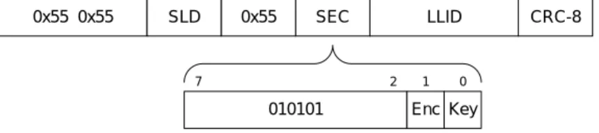
The fifth octet of the preamble (immediately before the LLID) is used to carry security information.
1
2 0
7
0x55 0x55 SLD 0x55 SEC LLID CRC-8
010101 Enc Key
Figure 6 - Security Octet (1Down)
The DPoE System MUST set bit 1 in the security octet in the preamble of the 1Down frame to indicate
that the data transferred is cipher text, and set bit 0 to the key identification number used to encrypt the
frame. For 1Down encryption, bits [7:2] of the security octet are reserved, and the DPoE System MUST
set them to 010101 (binary), matching the normal IDLE pattern. When encryption is disabled, the DPoE
System MUST set the 1Down security octet to a value of 0x55.
6.2 10G Zero-Overhead Cipher Suite (10Down, 10Bi)
This section defines the frame format used with encryption on 10G EPON devices. Note that the upstream
path uses this encryption method even with a 10G down / 1G up PON.
6.2.1 10G Zero-Overhead Frame Format
In the 10G mode, as in the 1G mode, the entire frame from DA through FCS is encrypted. Only the
preamble remains as clear-text.
Preamble DA SA Type/Len Data FCS
Cipher Text Region
Pad
Figure 7 - Cipher Text Region (10Down, 10Bi)
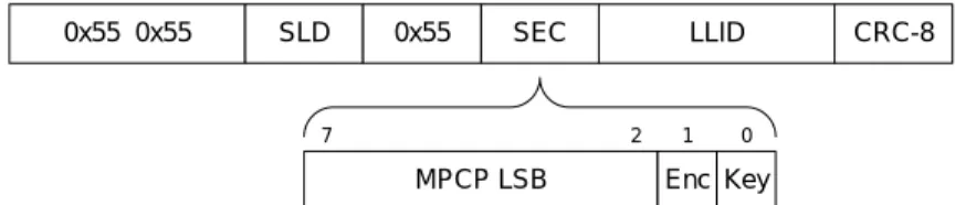
0x55 0x55 SLD 0x55 SEC LLID CRC-8
1
2 0
7
MPCP LSB Enc Key
Figure 8 - Security Octet (10G Zero Overhead)
Fields in the security octet are:
Bits Meaning
7:2 LSB of the MPCP time of the frame DA at the transmitter
1 1 if frame is encrypted; 0 if frame is not encrypted
0 Key identification number (0..1) of the key used to encrypt this frame
7 KEY MANAGEMENT PROTOCOLS
7.1 1G Downstream-only Key Exchange Protocol
The key exchange protocol defined in this section MUST be used by DPoE System operating at 1 Gbps
using the downstream-only encryption option. The key exchange protocol defined in this section MUST
be used by D-ONU operating at 1 Gbps using the downstream-only encryption option.
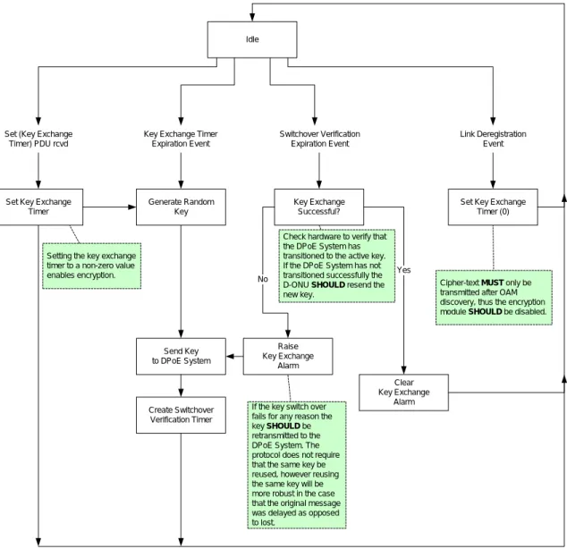
Generate Random Key Send Key to DPoE System Create Switchover Verification Timer Clear Key Exchange Alarm Raise Key Exchange Alarm No Yes Set Key Exchange
Timer
Key Exchange Successful?
Setting the key exchange timer to a non-zero value enables encryption.
Set Key Exchange Timer (0) Link Deregistration
Event
Cipher-text MUST only be transmitted after OAM discovery, thus the encryption module SHOULD be disabled. Key Exchange Timer
Expiration Event
Switchover Verification Expiration Event
Check hardware to verify that the DPoE System has transitioned to the active key. If the DPoE System has not transitioned successfully the D-ONU SHOULD resend the new key.
If the key switch over fails for any reason the key SHOULD be retransmitted to the DPoE System. The protocol does not require that the same key be reused, however reusing the same key will be more robust in the case that the original message was delayed as opposed to lost.
Set (Key Exchange Timer) PDU rcvd
Idle
Figure 9 - D-ONU Key Exchange State Machine
7.1.1 Set Key Exchange Timer
After MPCP and OAM discovery, the DPoE System configures a given logical link as a secure channel
by sending a Set Key Exchange Timer OAM message to the D-ONU. This message contains a single
timer value, TimeOut, which will be used by the key exchange process. The D-ONU then transmits a Set
Key Exchange Timer Ack indicating to the DPoE System that the link was successfully configured.
Figure 10 - Setting the Key Exchange Timer
The DPoE System SHOULD implement a retry mechanism in the event that the ACK is not received.
7.1.2 Create Key Exchange TimerWhen a key exchange occurs, the
D-ONU creates a timer initialized to the value specified by the Key
Exchange Timer attribute that was used to enable encryption. The use of this timer is described in Section
7.1.7, Key Exchange Timer Expiration Event. The D-ONU MUST only accept a Key Exchange Timer
value of at least 10 seconds. The D-ONU MUST NOT accept a Key Exchange Timer value of more than
65,535 seconds.
7.1.3 Generate Random Key
Once a given logical link has been configured as a secure channel, the D-ONU immediately generates a
128 -bit random key string associated with the link. The key string will be used by the DPoE System to
encrypt data and by the D-ONU to decrypt cipher text received from the DPoE System.
DPOE System DPOE ONU
Set Key Exchange Timer (Timeout) Set Key Exchange Timer Ack
7.1.4 Send Key to DPoE System
The D-ONU immediately transfers the key string along with a 1-bit key identification number to the
DPoE System. The DPoE System uses the key string to generate cipher text using the cipher algorithm
specified for the cryptographic method. (See Section 11, Cryptographic Methods.)
Figure 11 - Send Key to the DPoE System
7.1.5 Create Switchover Verification Timer (Optional)
After transferring the key to the DPoE System, the D-ONU SHOULD create a failsafe switchover
verification timer. When this timer expires, the D-ONU verifies that the DPoE System is transferring
cipher-text on the associated logical link using the latest key. If the link is still receiving plain-text, or data
encrypted with the previous key, the D-ONU SHOULD retransmit the key to the OLT in the DPoE
System. Refer to Section 7.1.7, Key Exchange Timer Expiration Event, for more information on Key
Exchange.
DPoE System Link
Switchover Verification Timer Expired Send Key Exchange Failure Alarm
Send New Key (key, number)
If the link detects that the key exchange has not been made in the required interval, it should raise an alarm and resend the key to the DPoE System.
The D-ONU mustcontinue to
retransmit the same key until it has been acknowledged by the DPoE System.
The DPoE System
implementation mustaccept
the key exchange failure alarm as well as a new key. The
order of events must notbe
assumed.
Send New Key
Set Switchover Verification Timer
Figure 12 - Key Exchange Failure Detected by Link
DPoE System D-ONU
Send New Key (key, 0)
Set Key Exchange Timer
Cipher Text Below Plain Text
The key number of the first key exchanged MAY be any value (0 or 1).
The D-ONU MUST wait at least 1 second before verifying that the key exchange has taken place. This is
long enough to guarantee that the D-ONU has received at least one encrypted MPCP GATE PDU from
the DPoE System. The D-ONU SHOULD NOT wait more than ½ of the actual key exchange timer value
before verifying the key exchange.
7.1.6 Switchover Verification Event (Optional for ONU)
This event triggers the D-ONU to validate that the encryption key has been successfully updated by the
DPoE System. If the key exchange has not occurred successfully, the D-ONU SHOULD send an
appropriate alarm message to the DPoE System on the failing link and resend the key. Refer to Section
7.1.5, Create Switchover Verification Timer (Optional).
7.1.7 Key Exchange Timer Expiration Event
This event will trigger the D-ONU to generate a new security key and transfer it to the DPoE System. The
D-ONU MUST retain the original key and transfer the new key with a different key identification number
from the original. The D-ONU MUST accept and decrypt cipher-text with either the active or the next
key. The key identification number transferred in the preamble of the cipher-text identifies the encryption
key used by the DPoE System for that frame. The key exchange mechanism expires keys to limit the
useful lifetime of a successful key extraction attack. Refer to Figure 13 below depicting two key exchange
cycles.
On the DPoE System, expiration of the key exchange timer SHOULD generate an alarm to management
software.
7.1.8 Link Deregistration Event
Link deregistration triggers the D-ONU to disable security for that link (only). Security should be
re-enabled upon link discovery.
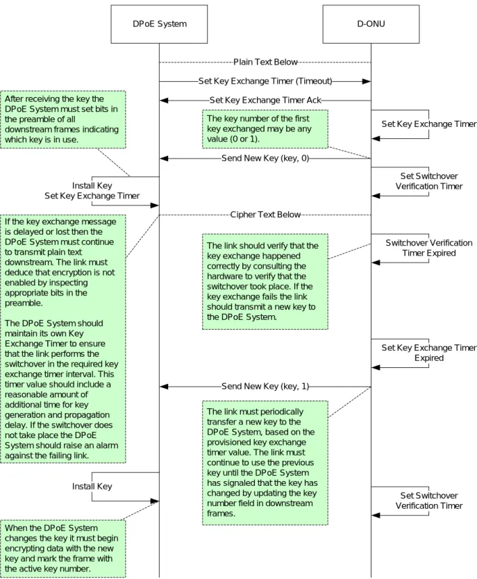
DPoE System D-ONU
Set Key Exchange Timer (Timeout)
Set Key Exchange Timer Ack
Send New Key (key, 0) After receiving the key the
DPoE System must set bits in the preamble of all
downstream frames indicating which key is in use.
Set Key Exchange Timer
Install Key Set Key Exchange Timer
Cipher Text Below Plain Text Below
Set Switchover Verification Timer
Switchover Verification Timer Expired The link should verify that the
key exchange happened correctly by consulting the hardware to verify that the switchover took place. If the key exchange fails the link should transmit a new key to the DPoE System.
Set Key Exchange Timer Expired If the key exchange message
is delayed or lost then the DPoE System must continue to transmit plain text downstream. The link must deduce that encryption is not enabled by inspecting appropriate bits in the preamble.
The DPoE Systemshould maintain its own Key Exchange Timer to ensure that the link performs the switchover in the required key exchange timer interval. This timer value should include a reasonable amount of additional time for key generation and propagation delay. If the switchover does not take place the DPoE System should raise an alarm against the failing link.
Send New Key (key, 1)
The link must periodically transfer a new key to the DPoE System, based on the provisioned key exchange timer value. The link must continue to use the previous key until the DPoE System has signaled that the key has changed by updating the key number field in downstream frames.
Set Switchover Verification Timer Install Key
When the DPoE System changes the key it must begin encrypting data with the new key and mark the frame with the active key number.
The key number of the first key exchanged may be any value (0 or 1).
Figure 13 - Changing Keys On Timer Expiration
7.1.9 Detecting Key Exchange Failures at the DPoE System
The DPoE System SHOULD detect failure to receive a new key from the D-ONU within the provisioned key exchange time. The DPoE System MAY deregister the logical link when it fails to receive a new key from the
D-ONU. The D-ONU SHOULD retry the key exchange message; see Section 7.1.6, Switchover Verification Event (Optional for ONU), for more details.
Key exchange timer expried
The DPoE System should maintain a timer to verify that the key is exchanged within the provisioned key exchange interval. If the key is not exchanged an alarm should
be raised. The link maybe
deregistered by the DPoE System.
Force Link Deregister Send New Key
DPoE System Link
Figure 14 - Key Exchange Failure Detected By DPoE System
It is also possible that the DPoE System could fail to receive a response to the initial Set Key Exchange Timer sent to the D-ONU. The DPoE System SHOULD retry this message. If no response is received from the D-ONU, the DPoE System SHOULD deregister the logical link.
Set Key Exchange Timer (0)
Set Key Exchange Timer Ack
Set Key Exchange Timer (0) If the DPoE System fails to
receive an Ack within 1 second, the DPoE System should attempt to retransmit the message. The DPoE
System mayretransmit the
message before 1 second. 1 Sec.
Force Link Deregister
If after 3 consecutive attempts the DPoE System does not receive an Ack the DPoE System should deregister the link. The DPoE System may retry more than 3 times.
DPoE System Link
7.1.10 DPoE OAM Key Exchange Messages
Key exchange message formats and attributes are defined by the [DPoE-SP-OAMv2.0] specification. The
Key Exchange PDU type carries key values, while the Encrypt Key Expiry Time attribute controls the
Key Exchange Timer interval.
7.1.11 Summary of 1Down Encryption Parameters
Property Description Unit Min Max Default
Key Exchange Timer A repeating timer, an instance of which should be maintained by the D-ONU for every link
configured as a secured channel.
N/A N/A N/A N/A
Key Size Number of octets of the key value to follow. Used to determine the length of the Encryption Key.
Octet 16 16 16
Key
Security Key Encryption Key
String of bits used as input into the AES
algorithm. A unique security key is generated by the D-ONU for each link configured as a secure channel.
N/A 0 2^128 - 1 N/A
Encryption Key Expiry Time
Key Exchange Timer Value
Time interval at which the D-ONU shall generate a new Key and transfer it to the DPoE System. A separate attribute is defined for each link associated with a particular D-ONU. Setting the attribute to 0 for a given link shall disable security on that link.
Seconds 10 (0)
65535 0
Encryption Enabled Flag present in every forwarded frame that is used to determine if the payload contains plain-text or cipher-plain-text.
1= enabled, 0=disabled
N/A 0 1 0
Key Identification Number
The key identification number sent in every forwarded frame configured as a secure link and used by the D-ONU to determine which of the two possible keys associated with the link shall be used to decrypt the payload.
N/A 0 1 N/A