1280 Massachusetts Avenue Cambridge, MA 02138 Business voice: (617) 576-2760 Business fax: (617) 576-3609 Tech support fax: (617) 354-3068
Tech support email: [email protected] Web site: http://www.motu.com
Mark of the Unicorn, Inc.
Digital Timepiece
SAFETY PRECAUTIONS AND ELECTRICAL REQUIREMENTS
WARNING: TO REDUCE THE RISK OF FIRE OR ELECTRICAL SHOCK, DO NOT EXPOSE THIS APPLIANCE TO RAIN OR OTHER MOISTURE.
CAUTION: TO REDUCE THE RISK OF ELECTRICAL SHOCK, DO NOT REMOVE COVER. NO USER-SERVICEABLE PARTS INSIDE. REFER SERVICING TO QUALIFIED SERVICE PERSONNEL.
WARNING: DO NOT PERMIT FINGERS TO TOUCH THE TERMINALS OF PLUGS WHEN INSTALLING OR REMOVING THE PLUG TO OR FROM THE OUTLET. WARNING: IF NOT PROPERLY GROUNDED THE Digital Timepiece COULD CAUSE AN ELECTRICAL SHOCK.
The Digital Timepiece is equipped with a three-conductor cord and grounding type plug which has a grounding prong, approved by Underwriters' Laboratories and the Canadian Standards Association. This plug requires a mating three-conductor grounded type outlet as shown in Figure A below.
If the outlet you are planning to use for the Digital Timepiece is of the two prong type, DO NOT REMOVE OR ALTER THE GROUNDING PRONG IN ANY MANNER. Use an adapter as shown below and always connect the grounding lug to a known ground. It is recommended that you have a qualified electrician replace the TWO prong outlet with a properly grounded THREE prong outlet. An adapter as illustrated below in Figure B is available for connecting plugs to two-prong receptacles.
WARNING: THE GREEN GROUNDING LUG EXTENDING FROM THE ADAPTER MUST BE CONNECTED TO A PERMANENT GROUND SUCH AS TO A PROPERLY GROUNDED OUTLET BOX. NOT ALL OUTLET BOXES ARE PROPERLY GROUNDED.
If you are not sure that your outlet box is properly grounded, have it checked by a qualified electrician. NOTE: The adapter illustrated is for use only if you already have a properly grounded two-prong receptacle. Adapter is not allowed in Canada by the Canadian Electrical Code. Use only three wire extension cords which have three-prong grounding type plugs and three-prong receptacles which will accept the Digital Timepiece plug.
IMPORTANT SAFEGUARDS
1. Read instructions - All the safety and operating instructions should be read before operating the Digital Timepiece. 2. Retain instructions - The safety instructions and owner's manual should be retained for future reference. 3. Heed Warnings - All warnings on the Digital Timepiece and in the owner's manual should be adhered to. 4. Follow Instructions - All operating and use instructions should be followed.
5. Cleaning - Unplug the Digital Timepiece from the computer before cleaning and use a damp cloth. Do not use liquid or aerosol cleaners. 6. Overloading - Do not overload wall outlets and extension cords as this can result in a risk of fire or electrical shock.
7. Power Sources - This Digital Timepiece should be operated only from the type of power source indicated on the marking label. If you are not sure of the type of power supply to your location, consult your local power company. 8. Power-Cord Protection - Power-supply cords should be routed so that they are not likely to be walked on or pinched by items placed upon or against them. Pay particular attention to cords and plugs, convenience receptacles, and
the point where they exit from the Digital Timepiece.
9. Lightning - For added protection for the Digital Timepiece during a lightning storm, unplug it from the wall outlet. This will prevent damage to the Digital Timepiece due to lightning and power line surges. 10. Servicing - Do not attempt to service this Digital Timepiece yourself as opening or removing covers will expose you to dangerous voltage and other hazards. Refer all servicing to qualified service personnel. 11. Damage Requiring Service - Unplug the Digital Timepiece from the computer and refer servicing to qualified service personnel under the following conditions.
a. When the power supply cord or plug is damaged.
b. If liquid has been spilled or objects have fallen into the Digital Timepiece. c. If the Digital Timepiece has been exposed to rain or water.
d. If the Digital Timepiece does not operate normally by following the operating instructions in the owner's manual. e. If the Digital Timepiece has been dropped or the cabinet has been damaged.
f. When the Digital Timepiece exhibits a distinct change in performance, this indicates a need for service.
12. Replacement Parts - When replacement parts are required, be sure the service technician has used replacement parts specified by the manufacturer or have the same characteristics as the original part. Unauthorized substitutions may result in fire, electric shock or other hazards.
13. Safety Check - Upon completion of any service or repairs to this Digital Timepiece, ask the service technician to perform safety checks to determine that the product is in safe operating conditions.
ENVIRONMENT
Operating Temperature: 10°C to 40°C (50°F to 104°)
AVOID THE HAZARDS OF ELECTRICAL SHOCK AND FIRE
Do not handle the power cord with wet hands. Do not pull on the power cord when disconnecting it from an AC wall outlet. Grasp it by the plug.
INPUT
3-prong plug Grounding prong
Properly grounded 3-prong outlet
Grounding lug Screw
3-prong plug
Adapter
Make sure this is connected to a known ground.
Two-prong receptacle
CHAPTER
Contents
Chapter 1 – About the Digital Timepiece
5 Packing list
5 About this guide
5 Register for technical support
5 What is the Digital Timepiece?
Chapter 2 – Degrees of Accuracy
9 Before you go any further…
9 Sample-accurate sync
9 Frame-accurate sync with phase-lock
10 Frame-accurate sync
10 Frame-accurate triggering
11 Front Panel Quick Reference
12 Rear Panel Quick Reference
Chapter 3 – Installation
13 Overview
14 Computers
16 Digital Multitrack tape decks
18 Working with the Tascam DA-88
22 Word Clock Devices
24 S/PDIF devices
27 Video
28 SMPTE time code devices
29 MIDI Time Code devices
29 Alesis LRC
30 MMC control surfaces
Chapter 4 – Front Panel Settings
33 Overview
34 About synchronization
34 Choosing a time base mode
36 Internal 36 MTC 36 LTC 36 Video/Internal 36 Video/MTC 36 Video/SMPTE (LTC) 37 Word 1x/Internal 37 Word 1x/MTC 37 Word 1x/LTC 37 Word 256x/Internal 37 Word 256x/MTC 38 Word 256x/LTC 38 Word 1x/Video/Internal 38 Word 1x/Video/MTC 38 Word 1x/Video/LTC 38 Word 1x/Video/VITC 38 Word 1x/Video/Sony 39 S/P DIF/Internal 39 Control track 1 or 2
39 Word 1x/Control track 1 or 2
39 DA-88
39 Word 1x/DA-88
39 ADAT
39 Word 1x/ADAT
40 the SMPTE frame rate setting
41 The Word clock rate setting
Chapter 5 – Example Setups
45 Overview
45 The Digital Timepiece as master
46 Video as time base master
47 Devices that cannot act as a slave
48 Using an Alesis BRC or Tascam RC-848
Chapter 6 – Converting/Generating Time Code
49 Overview
49 Starting playback
49 Deferred playback
50 Generating or Converting time code
Chapter 7 – Striping Time Code
53 Overview
54 General procedure
55 Striping frame-locked LTC onto video
55 Striping SMPTE on a multitrack tape deck
58 Recording burn-in & other graphics
Chapter 8 – MIDI Machine Control
59 Overview
59 How MMC works
59 A recommended scenario for MMC
60 MMC Device IDs
62 Setting up MMC slaves
63 Setting up a MMC transport master
64 MMC control of record functions
Chapter 9 – Digital Timepiece & Performer
67 Overview
67 Getting the Digital Timepiece to appear in Per-former’s MMC window
67 Slaving Performer
68 Using Performer as transport master
69 MMC record commands
71 Video streamers
72 Controlling a DA-88/SY-88 with Performer
Chapter 10 – Digital Timepiece & Other Sequencers
75 Overview
75 Establishing communication
75 Slaving your sequencer
76 Using your sequencer as transport master
77 MMC record commands
Chapter 11 – Digital Timepiece & OMS
79 Overview
79 ClockWorks and OMS
81 Preparing ClockWorks
81 Preparing OMS
81 Adding the DTP to your OMS setup
82 Using AV Controls
Chapter 12 – Digital Timepiece & Pro Tools
83 Overview
84 Pro Tools, ClockWorks, OMS & FreeMIDI
85 Enabling OMS emulation in FreeMIDI
85 Preparing OMS
86 Pro Tools as master
88 Pro Tools as slave
91 Pro Tools and Triple-sync
91 Transport control 92 Lockup time Chapter 13 – Alesis LRC 93 Using an Alesis LRC 93 LRC button functions 94 LRC Calibration Chapter 14 – Troubleshooting
95 Common problems and solutions
98 Customer Support
98 Replacing Disks
CHAPTER
1
About the Digital Timepiece
Thank you for purchasing the Digital Timepiece™! PACKING LIST
Your Digital Timepiece box should have the following items in it. If not, contact Mark of the Unicorn customer service at (617) 576-2760. ■ Digital Timepiece
■ Power cord
■ Digital Timepiece Manual ■ ClockWorks™ Manual
■ ClockWorks™ software installer disks ■ Registration card
ABOUT THIS GUIDE
This guide provides important information about installing and setting up the Digital Timepiece. There is a companion guide for the Macintosh software console that ships with the Digital Timepiece called the ClockWorks User’s Guide.
REGISTER FOR TECHNICAL SUPPORT Before you go any further, take a moment to fill out and mail in the registration card included in this package. Doing so entitles you to:
■ free, unlimited technical support via email ■ free newsletters
■ new product information
Since Mark of the Unicorn can only provide customer service and technical support to registered users, please send in the card right away.
WHAT IS THE DIGITAL TIMEPIECE? Think of the Digital Timepiece as the synchroni-zation hub for your recording studio. It provides stable, centralized synchronization services for most analog, digital audio, and video equipment found in today’s recording studio. Until now, locking together ADAT™, DA-88™, Pro Tools™, word clock audio devices, S/PDIF devices, video decks, SMPTE time code devices, MIDI Machine Control devices and computers has been difficult — if not impossible. The Digital Timepiece can connect to all of these types of devices and synchronize them with one another.
A computer is not required
You do not need a computer to use a Digital Timepiece. Essential settings are available directly on the front panel. Once you choose an operational mode with the TIME BASE controls, the Digital Timepiece will generate or convert all forms of synchronization necessary to keep all connected devices synchronized with one another.
Degrees of accuracy
Digital audio devices found in today’s studio support varying degrees of accuracy when it comes to synchronization. The Digital Timepiece supplies the best possible accuracy for each type of device that it supports. Most devices fall into the following basic categories of accuracy:
■ Sample accurate sync
■ Frame-accurate sync with phase lock ■ Frame-accurate sync with no phase lock ■ Frame-accurate triggering
Synchronization firsts
The Digital Timepiece offers several synchroni-zation firsts. For example, you can now synchronize a stack of Alesis ADAT™ recorders with a stack of Tascam DA-88™ recorders with ‘plug-and-play’ ease and sample-accurate timing. The Digital Timepiece also works with other devices that support the ADAT and DA-88 proprietary sync protocols, such as the Panasonic MDA-1™, SONY PCM-800™ and Tascam DA-38™.
The components of sync
The Digital Timepiece supplies all of the necessary components for stable, sample-accurate synchro-nization: address (SMPTE time code location and audio sample number), time base (word clock), and machine control (for transport and cueing). You choose an external source — or the Digital Timepiece itself — as a time base and address master, and then the Digital Timepiece
continuously generates all other synchronization formats, locking together all connected devices with frame-accurate timing. Sample-accurate timing is achieved with devices that allow it, such as ADATs and DA-88s.
The flexibility you need
The Digital Timepiece is more flexible than most synchronizers because it allows you to choose different master sources for time base, address and transport, as best fits your studio setup. For example, you could choose house sync video as the master time base, the Digital Timepiece as the address (time code) master, and your computer software as the transport master.
All standard digital audio sync formats
Digital audio synchronization formats supported include word clock, Digidesign 256x ‘superclock’ and S/PDIF. These industry standard formats allow the Digital Timepiece to synchronize a wide variety
of digital audio systems, including Digidesign Pro Tools™ 4.0, Pro Tools Project™, stand-alone hard disk recorders, digital mixers, computer-based digital audio workstations, S/PDIF devices (such as DAT recorders) and Digidesign’s Audiomedia™ II and III cards.
Expensive add-ons are not needed
Because the Digital Timepiece directly supports third-party synchronization formats like
‘superclock’ and ADAT Sync, it eliminates the need for expensive synchronization add-on equipment such as Digidesign’s SMPTE Slave Driver™, the Digidesign Video Slave Driver™, Alesis BRC™, Tascam SY-88™ sync card and others. The Digital Timepiece dramatically undercuts the cost and setup overhead of these other devices while offering most of the same features in a compact, efficient, single rack-space unit.
All SMPTE time code formats
The Digital Timepiece can also generate and slave to all forms of SMPTE time code, including LTC, VITC and MTC (MIDI Time Code). All SMPTE frame formats are supported when generating and reading time code, including 29.97 drop and non-drop for NTSC video applications. These SMPTE sync features allow the Digital Timepiece to synchronize with computers, analog tape decks, stand-alone hard disk recorders, MIDI devices, and virtually anything that can either generate or slave to SMPTE or MIDI Time Code.
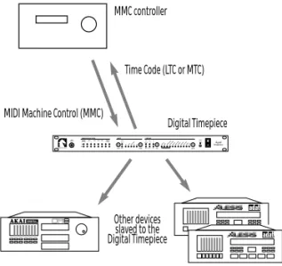
MIDI Machine Control
The Digital Timepiece supports MIDI Machine Control (MMC) transport and record functions. These features allow you to control your entire rig from a single source (such as your MMC-compatible computer software), eliminating the need for expensive, dedicated hardware control surface add-ons such as the Alesis BRC™ and Tascam RC-848™ for basic machine control tasks.
SONY 9-pin machine control
The Digital Timepiece includes support for the SONY 9-pin machine control format. You can connect a SONY 9-pin compatible video deck, which can then be slaved to the Digital Timepiece. This allows you to control the video deck, along with all of your other gear, from your favorite MMC-compatible computer software or any MMC-compatible hardware controller.
Conversely, the Digital Timepiece can slave to the 9-pin video deck.
Advanced video features
The Digital Timepiece provides many other essential video features. The rear panel has two BNC video jacks (IN and OUT) in addition to its SONY 9-pin connector. Internally, the Digital Timepiece has a built-in video sync generator, which can be synchronized with the Digital Timepiece’s audio phase lock engine or run independently of the Digital Timepiece’s synchro-nization features. The VIDEO IN jack allows the Digital Timepiece to slave to any NTSC or PAL video source, such as house sync video or VTR output. The VIDEO OUT jack can display whatever is being received on the input, or it can produce blackburst. In either case, the Digital Timepiece can overlay up to twelve lines of text and information on its video output signal, including a large and small SMPTE time code burn-in, status information (e.g. the Digital Timepiece’s current sample rate output), MIDI sequencer triggered streamers with punch, and numerous lines of user-programmed text (such as client and project names). Text lines can be positioned vertically as desired.
44.1 and 48 kHz with pull up/down
The Digital Timepiece supports 44.1kHz and 48kHz sampling rates. It also supplies 0.1% pull-up and pull-down at both rates, an essential feature for
down rate while working with film in video format, you can easily avoid synchronization and drift problems that arise from the 0.1% speed difference between the film transfer rate of 30fps and the NTSC video playback rate of 29.97fps.
Proprietary technology
The Digital Timepiece delivers pristine sound and an extremely stable, high-resolution digital audio time base with no dithering, rounding, or software delays. This level of performance is made possible by custom-designed VLSI technology and a proprietary high-frequency phase engine.
Fast lockup time
Depending on the specific scenario in which the Digital Timepiece is being operated, its lock-up time can be as fast as one second. Fastest lockup times are achieved by slaving the Digital Timepiece to house sync video (“blackburst”) or by running under its own internal clock. When slaving the Digital Timepiece to SMPTE or MIDI time code (without video as a time base), lock up time is typically 2-4 seconds, depending on the overall stability of the incoming time code.
Control track
A new, proprietary Mark of the Unicorn synchro-nization format, called ‘Control Track’, is supplied via two 8-pin circular DIN sockets on the Digital Timepiece rear panel. By means of high-resolution sample address information, Control Track can synchronize two Digital Timepieces with sample-accurate timing.
Stand-alone and computer-based operation
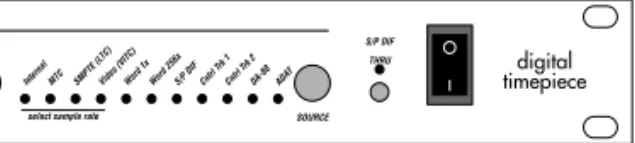
The Digital Timepiece can be operated in a computer-based setup or as a stand-alone synchronizer. The front panel supplies buttons and status LEDs for making all of the necessary basic operational settings. You can choose the overall operating mode (called the ‘time base mode’), the
code format (30, 29.97, 29.97 drop, 25 and 24). Status LEDs are also supplied to indicate communication between the Digital Timepiece and devices connected to it. A convenient S/PDIF THRU button allows you to easily bypass the Digital Timepiece when transferring S/PDIF audio from one device to another — without having to swap cables. The front panel also has a quarter inch phone jack for an Alesis LRC™ or compatible controller.
The Digital Timepiece rear panel
The Digital Timepiece rear panel has three input/ output pairs of BNC connectors for video, word clock and Digidesign superclock. A pair of RCA phone jacks supply S/PDIF input and output. Other rear panel connectors include a pair of standard ADAT 9-pin Sync In and Sync Out sockets, DA-88 15-pin Sync In and Sync Out sockets, a SONY 9-pin video sync jack, a pair of
quarter-inch phone jacks for SMPTE (LTC) input and output, two pairs of MIDI IN and OUT sockets, an RS-422 jack for optional connection directly to a Macintosh computer, and two additional circular DIN-8 sockets for the Digital Timepiece’s proprietary Control Track protocol.
Convenient software included
The Digital Timepiece™ ships with Macintosh console software that provides access to numerous additional features. For example, the console allows you to program SMPTE time code offsets for individual devices connected to the Digital Timepiece, such as a single ADAT within a chain of ADATs. You can even program individual track offsets for ADATs and DA-88s; track offsets can be specified as a number of samples. The console software also lets you control the Digital Timepiece’s video graphics features.
CHAPTER
2
Degrees of Accuracy
BEFORE YOU GO ANY FURTHER… Digital audio devices found in today’s studio support varying degrees of accuracy when it comes to synchronization. The Digital Timepiece supplies the best possible accuracy for each type of device that it supports. Here is a brief overview of several basic categories of accuracy to which most digital audio devices belong, starting with the highest (best). After you look them over, think about each device in your studio and the category it belongs to. Doing so will help you make better decisions when installing the Digital Timepiece, which supports a wide range of synchronization scenarios.
SAMPLE-ACCURATE SYNC
When two devices achieve sample-accurate sync, the master device and slave device are in
continuous, sample-accurate synchronization with each other. Not only are their sample clocks continuously aligned (phase-locked), sample for sample, but they also locate to —and start playing or recording on — exactly the same sample every time. For example, if the master device cues to sample number 49,856,237 in a recording, the slave device will cue to exactly the same sample. Resolution is 44.1 or 48 thousandths of a second. A slight bit of skew might be introduced due to analog filter delays. But if so, the skew will be consistent, so it will not cause phasing.
An example of devices that support this level of synchronization is a chain of ADAT tape recorders via their proprietary ADAT sync protocol. If you record a stereo track pair from one ADAT to another in two separate record passes, the stereo image would remain in perfect phase. The Digital
continuous phase-lock). But even more signifi-cantly, the Digital Timepiece can also make a stack of ADATs synchronize with a stack of DA-88s (which also support sample-accurate sync) at this level. The Digital Timepiece is the first
synchronizer to be able to do this.
FRAME-ACCURATE SYNC WITH PHASE-LOCK
When two devices achieve frame-accurate sync with phase-lock, master and slave device play back in continuous phase-lock with each other, sample for sample, with no phasing or drifting over time. However, the timing resolution at which the devices locate — and begin recording or playing back — is equivalent to the SMPTE time code frame rate being used (e.g. 30 frames per second). Digidesign Pro Tools is a classic example of a system that synchronizes at this level of accuracy. When slaving externally, Pro Tools locates and begins recording or playing according to MIDI Time Code it receives, which has a has a quarter frame resolution of 30 frames per second times four — or approximately a 120th of a second (or whatever time code frame rate is being used). Because MTC suffers from general MIDI delays and skewing, Pro Tools and systems like it also employ a software averaging scheme which helps with accuracy even further.
Note, however, that Pro Tools — as a slave — also requires a sample clock (Digidesign refers to it as “superclock” or “slave clock”) to keep it phase-locked with its master once it starts. While “superclock” maintains phase lock at normal digital audio sample rates (44.1 or 48 thousand
with the master digital clock during playback or recording, sample for sample, to prevent phasing (which causes distortion) or drifting (which causes sync problems). But the highest resolution at which Pro Tools can locate — and begin playing or recording — is one 120th of a second (quarter-frame resolution). If you transferred a stereo track pair in two separate record passes into Pro Tools, the stereo image would not be transferred in perfect phase. In other words, Pro Tools cannot start at exactly the same sample as other digital audio devices, like ADATs can. (Future versions of Pro Tools may provide sample accurate synchroni-zation capability.)
FRAME-ACCURATE SYNC
When two devices achieve frame-accurate sync without phase lock, master and slave remain in sync with each other, but their digital audio clocks are not kept in phase. Instead, they stay in continuous sync via time code, which has a resolution of a thirtieth of a second (or one of the other standard SMPTE time code frame rates). This form of synchronization inevitably causes two digital audio devices to phase with one another as they play, since the timing reference (30 frame per second time code) has such a lower resolution than their internal sample clocks.
An example of this type of sync would be a stand-alone hard disk recorder slaved to the Digital Timepiece via SMPTE time code only, with no word clock connection between the devices. The hard disk recorder would read the incoming time code and continually adjust its digital audio output to stay in sync with the time code.
FRAME-ACCURATE TRIGGERING
With frame-accurate triggering, unlike any of the continuous forms of sync already discussed, the master device only tells the slave device where to locate (at a specific time code location). But when the slave begins playing or recording, it runs under its own internal clock, inevitably drifting out of sync with the master, given enough time. The time it takes for drift to become noticeable depends on the devices involved and the situation in which they are being used. Timing resolution is
equivalent to frame rate being used (e.g. 30 frames per second).
Most devices today use one of the continuous forms of sync described earlier. You probably won’t encounter a device of this type in your work with the Digital Timepiece.
0
F
ront P
a
nel Quick Ref
e
renc
e
The output sta
tus ligh ts sho w when da ta is being sen t t o each output destina tion. W hen the Digital Ti mepiec e is idle (not gener at ing or co nv er ting time c ode),
the output ligh
ts will
flick
er about onc
e per
sec
ond as the Digital
Ti mepiec e c on tinuously checks f or devic es co nnec ted t o it. If a devic e is pr esen t, the Digital T imepiec e co nt in-ually checks f or its curr en t fr ame loca tion t o mak e sur e it is in sync
with the Digital Timepiec
e. W hen the Digital T imepiec e is gener at ing or c on ver ting time c ode
, the LEDs will
glo w c on tinuously . The C O MMUNICA TION ST ATUS ligh ts blink when da ta is sen t t o and fr om the Digital Ti mepiec e. Ti me c ode appears as a st eady glo w . P olling and “handshak ing ” messages appear as flick ering . If the Digital Ti mepiec e is curr en tly set t o Int ernal
mode (as sho
wn b
y the
TIME BASE LED t
o the righ t) — which mak es it the addr ess (time c ode) mast er , pr essing the STRIPE butt on mak es it begin gener at ing time co de (as w
ell as all other
sync forma ts) a t 0:00:00:00, unless y ou ha ve used the C lockW orks console soft w ar e t o set an y SMPTE star t time y ou wish. If an e xt ernal sour ce is curr en
tly chosen as the
addr ess mast er , pr essing this butt on w on ’t do an ything . The TA CH ligh t blinks onc e per sec
ond when the Digital
Ti mepiec e is either gener at -ing or c on ver ting time c ode . The L O CK ligh t glo w s when the Digital Ti mepiec e has succ essfully achie ved and is main taining lock up t o ex ternal time c ode . Fo
r time base modes
tha t r equir e y ou t o
manually choose the SMPTE time code fr
ame r
at
e,
pr
ess the FORMA
T butt on r epea tedly t o
choose the desir
ed ra te . Ho w ev er , for
time base modes tha
t mak e the Digital T imepiec e follo w e xt ernal time co de , this setting is made aut oma tically by the Digital Ti mepiec e, which senses the fr ame ra te of the inc oming time c ode . The
TIME BASE sec
tion of the fr on t panel is wher e y ou choose which co mponen ts of y our sy st em ar e the
time base mast
er and the time c
ode (addr ess) mast er . F or e xample , if y ou
choose video+SMPTE mode
, video
blackburst (house sync) c
ould be the
time base mast
er
, while SMPTE time
co de (L TC) fr om a VTR c ould be the addr ess mast er . Pr ess the RA TE butt on repea tedly t o choose one of six w or d clock r at es as sho wn b
y these four LEDs
.
The six possible r
at es ar e: ■ 48 kHz ■ 48 pull-up (+1%) ■ 48 pull-do wn (-1%) ■ 44.1 kHz ■ 44.1 pull-up ■ 44.1 pull-do wn Th is w or d clock r at e
setting only needs t
o be
set manually her
e when yo u ha ve selec ted the Digital T imepiec e, time co
de or video as the time
base mast er (with the TIME BASE c on tr ols on the righ t). O
ther time base
modes deriv e the w or d clock r at e fr om their re spec tiv e e xt ernal time base sour ce . W
hen one of these first
four LEDs is illumina
te d, the Digital Ti mepiec e co nt
rols the global w
or d clock r at e as det ermined by the w or d r at e settings on its fr on t panel (a t left).
All other time base modes deriv
e the w or d clock r at e fr om their r espec tiv e ex
ternal time base sour
ce . The L O CK indica to rs (A ddr ess and W or d) glo w st
eadily when the Digital
Ti
mepiec
e has
succ
essfully achie
ved and is main
taining lock up t o the curr en t addr
ess and time base
sour ces. T he Addr ess LED glo w s when the Digital Ti mepiec e is succ essfully r eading and/ or gener at ing time c ode . T he Wo rd LED glo w s
when the Digital
Ti
mepiec
e’
s digital audio
phase loop engine has stabiliz
ed and is curr en tly gener at ing or lock ing t o a time base . Pr
ess the SOURCE butt
on r
epea
tedly t
o choose the o
ver
all time base and time c
ode (addr ess) sour ce . T her e ar
e 28 possible settings but only 11 LEDs
, so man y time base modes ar e indica ted b y a c ombina tion of 2 or 3 illumina
ted LEDs (indica
ted
with a / sign belo
w
). B
elo
w is a brief summar
y of each mode:
Time base mode
Explanation Int ernal MT C SMPTE (L TC ) The selec
ted item is both time base and addr
ess (time code) master . Video / Int ernal Video / MT C Video / SMPTE (L TC ) Video ( VIT C) Video ser
ves as the time base mast
er and the other
chosen sour ce (Int ernal, MT C, LT C, or VIT C) is the address
(time code) master
.
Video SONY 9-pin
This mode is indic
at
ed by a blinking
Video LED
. Video
(fr
om the 9-pin deck or from house sync) is the time
base master and the 9-pin deck is addr
ess master (via
its 9-pin connec
tion). W or d 1x / Int ernal* W or d 1x / MT C* W or d 1x / SMPTE (L TC)* W or d 1x / contr ol track 1 and 2 W or d 1x / ADA T W or d 1x / DA-88 An ex ternal w or
d clock device ser
ves as the time base
master and the other chosen sour
ce (Int ernal, MT C, LT C, contr ol track, ADA T or
DA-88) is the address (time code)
master . W or d 1x / video / Int ernal W or d 1x / video / L TC W or d 1x / video / MT C W or d 1x / video / VIT C W or d 1x / video / S on y An ex ternal w or
d clock device ser
ves as the time base
master
. T
he ex
ternal w
or
d clock master device and the
Digital Ti mepiece ar e both r esolv ed t o video , so that
both devices can achiev
e accura
te video frame lock.
The
addr
ess master can be Int
ernal, LT C, MT C, VIT C or 9-pin. S/PDIF / Int ernal An ex ternal S/PDIF de vice ser
ves as the time base
master and the D
igital
Ti
mepiece is the address (time
code) master . Co ntr ol track 1 or 2 ADA T DA-88 The selec
ted item is both time base mast
er and addr
ess
(time code) master
.
W
hen the S/PDIF
THRU butt
on is pushed in,
the LED
illumina
te
s and the Digital
Ti
mepiec
e passes digital
audio signal fr
om its S/PDIF IN t
o its S/PDIF OUT jack.
The Digital Ti mepiec e cannot sla ve to an inc oming
S/PDIF signal when the
THRU butt on is engaged . W hen the THRU butt on is r
eleased (turned off
), the Digital Ti mepiec e can sla ve to an inc oming S/PDIF signal. In addition, it c on tinuously gener at es its o wn
S/PDIF signal on its S/PDIF output jack,
to which a co nnec ted devic e can sla ve . * Also a vailable in W or d 256x format for Pr o Tools syst ems.
0
Rear P
a
nel Quick Ref
e
renc
e
To c onnec t the Digital Ti mepiec e dir ec tly t o a Macin-tosh c omput er (without a separ at e MIDI in te rf ac e), co nnec t this RS422 por t t o the modem or prin ter por t of the Macin tosh. T his allo ws the Digital Ti mepiec e t o talk t o an y MIDI soft w ar e, and it ac ts as a standar d 1 MHz MIDI in te rf ac e. The Digital Ti mepiec e ev en allo ws MIDI devic es c onnec ted toits MIDI por
ts t
o c
ommuni-ca
te
with MIDI soft
w ar e running on the c omput er . U
se the MIDI por
ts t o c onnec t the follo wing types of MIDI de vic es: ■ A MIDI in te rfac e c onnec ted t o a co mput er (not nec essar y if the Digital Ti mepiec e is c onnec ted t o a Macin tosh
via the RS422 REMO
TE por t) ■ An y MIDI Machine C on tr ol (MMC) co mpa tible devic e ■ An y MMC c on tr oller , such as a JL C ooper CueP oin t™ or CS10™ ■ An y MIDI devic e or c omput er soft w ar e tha t y ou w ould lik e t o sla ve to MT C (MIDI Ti me C ode) ■ An y MIDI instr umen t, such as a syn the-siz er , sampler , drum machine , et c. The Digital Ti mepiec e must either be a t the
beginning or end of a chain of ADA
Ts. Ac co rd ingly , nev er c onnec t both the S ync In and S
ync Out sock
ets a
t the same time
. Only
use one or the other
. In most cir cumstanc es , yo u will w an t the Digital Ti mepiec e t o be the sync mast er o ver y our ADA T (or chain of ADA Ts). If so , c onnec t the Digital Ti mepiec e’ s ADA T S
ync Out por
t t o the S ync In of y our ADA T, and , if y ou ha ve others
, chain them off
of the first ADA
T as dir ec ted in y our ADA T manual. T he ADA T S ync In por t allo ws the Digital Ti mepiec e t o be the sla ve of an ADA T (or a
t the end of a chain of ADA
Ts), which, in turn, c ould be c on tr olled b y a BRC. Not e tha t
all of this applies t
o other ADA T-c ompa tible decks as w ell, such as the F ost ex RD-8. W ORD 256x is Digidesign ’s
own special fla
vo r of w or d clock. It w
orks with Digidesign
syst
ems only — ones tha
t
ha
ve
w
or
d clock jacks with a
label on them something lik
e: ■ “Sla ve clock” ■ “Super clock” ■ “W or d 256x ” Co mpa tible sy st ems include Pr o T ools™, P ro T ools Pr ojec t™ (formerly called “S ession 8”) and P ro Tools III™. Co nnec t a SONY 9-pin co mpa tible video tape r ec or der ( VTR) her e. T his co nnec tion allo ws the Digital Ti mepiec e t o be either a mast er of or sla ve to a SONY 9-pin co mpa tible video deck or other de vic e. CO NTROL TRA CK is the Digital Ti mepiec e’ s o wn, pr oprietar y synchr oniza tion forma t. It carries all thr ee c omponen ts of synchr oniza tion: w or d r at e, addr ess and tr anspor t infor-ma tion. C onnec t an y devic e tha t suppor ts it , such as another Digital Ti mepiec e. If y ou w an t t o sla ve the Digital Ti mepiec e t o an S/PDIF de vic e, c onnec t the mast er S/PDIF signal to the Digital Ti mepiec e S/PDIF IN c onnec to r. An S/PDIF de vic e can be sla ved t o the Digital Ti mepiec e via the S/ PDIF output c onnec to r, which c on tinuously gener at es S/PDIF sync , unless the THRU butt on is pushed in on the fr on t panel, in which case it
simply passes input t
o its output . Co nnec t an y standar d digital audio w or d clock devic e, such as a stand-alone har d disk re co rder , t o these co nnec to rs. D o not co nnec t Digidesign har d disk r ec or ding syst ems her e. F or Digidesign sy st ems , use the W ORD 256x co nnec to rs inst ead . To VIDEO IN, c onnec t an y video sour ce
, such as house sync
black-burst or a VTR. To VIDEO OUT , co nnec t an y video destina tion,
such as a video monit
or or an y devic e tha t r equir es video sync . The Digital Ti mepiec e’ s time c ode burn-in displa
y and other video
displa
y options ar
e view
ed fr
om
its video output
.
The Digital
Ti
mepiec
e has a
built-in video sync gener
at or . F or impor tan t informa tion about ho
w the video sync gener
at or in te ra ct
s with the Digital
Ti mepiec e’ s synchr oniza tion fea tur es , see chapt er 9, “W orking with Video ” (page 67).
The SMPTE IN and OUT jacks ar
e standar d tip/ ring , balanc ed +4dB co nnec to rs for SMTPE LT C. C onnec t a L TC sour ce , such as a multitr
ack tape deck
or the audio fr om a VTR, to SMTPE IN. T he
SMPTE OUT jack can go to an
y destina
tion,
such as a stand-alone har
d disk r ec or der , a time c ode tr ack on a tape deck, et c. The Digital Ti mepiec e must either be a t the
beginning or end of a chain of
DA-88s. Ac co rd ingly , nev er c onnec t both the S ync In and S
ync Out sock
ets a
t the same time
. Only
use one or the other
. In most cir cumstanc es , yo u will w an t the Digital Ti mepiec e t o be the sync mast er o ver y
our DA-88 (or chain of
DA-88s). If so , c onnec t the Digital Ti mepiec e’ s DA-88 S
ync Out por
t t o the S ync In of y our DA-88, and , if y ou ha ve others ,
chain them off of the fi
rst DA-88 as dir
ec
ted
in y
our DA-88 manual.
T he DA-88 S ync In por t allo ws the Digital Ti mepiec e t o be the sla ve of an DA-88 (or a
t the end of a chain of
DA-88s), which, in turn, c ould be c on tr olled by a RC-848. Not e tha
t all of this applies t
o other DA-88 c ompa tible decks as w ell, such as the Ta scam DA-38.
CHAPTER
3
Installation
OVERVIEW
Because the Digital Timepiece supports a wide range of devices, this installation guide is divided into sections. Each section explains how to connect an individual type of gear to the Digital Timepiece. It may also briefly discuss other important information, such as special considerations or operating requirements you need to know to successfully operate the gear with the Digital Timepiece.
For sections that do not apply to you (you don’t own that specific piece of equipment, for example), just skip over them.
Computers . . . .14
Digital Multitrack tape decks . . . .16
Word Clock Devices . . . .22
S/PDIF devices. . . .24
Video . . . .27
SMPTE time code devices . . . .28
MIDI Time Code devices. . . .29
Alesis LRC. . . .29
MMC control surfaces . . . .30
If your device isn’t specifically mentioned
If you have a device that is not specifically mentioned in this installation guide, read the general description of each device category to see if your device falls in that category. If it does, the general description provided — together with your device’s instructions — should be enough to get it working with the Digital Timepiece.
Also check these other resources for late-breaking information about new devices that can be used with the Digital Timepiece:
■ Inserts included with this manual ■ Our Web site (www.motu.com)
COMPUTERS
The Digital Timepiece serves as an excellent way to synchronize MIDI software and computer-based digital audio workstations with the rest of the gear in your studio. If your software supports MIDI Machine Control (MMC), you can control the transports of everything from your computer. If your software supports MMC record functions, you can accomplish basic recording tasks from your computer, too, such as arming tracks, recording on them, and even recording automated punch-ins.
The Digital Timepiece does not require a computer to perform its basic synchronization duties. A computer does provide one important advantage: it allows you to run the Digital Timepiece’s control panel software, called ClockWorks™, which gives you access to features in the Digital Timepiece that are not available from the front panel.
For information about installing and using the Digital Timepiece software console, called ClockWorks™, see the ClockWorks User’s Guide
that accompanies this guide.
How it works
Computer software communicates with the Digital Timepiece via either MIDI Time Code (MTC), MIDI Machine Control (MMC) or both (Figure 3-1). Software on the computer slaves to MTC generated by the Digital Timepiece. Conversely, software that supports MMC can send MMC transport commands (play, stop, rewind, locate, etc.) to the Digital Timepiece.
☛
Digital audio workstations that involve additional hardware installed inside the computer or connected externally to the computer may or may not require these MIDI connections in lieu of connections made directly between the hardware and the Digital Timepiece.Figure 3-1: How a computer software communicates with the Digital Timepiece.
Connecting a Macintosh
There are two different ways you can connect a Macintosh to the Digital Timepiece:
■ With a standard RS422 (circular “DIN-8”) cable and the Digital Timepiece’s built-in serial port (Figure 3-2)
■ With MIDI cables and a separate MIDI interface (Figure 3-3)
There are no performance or operational advantages either way, so the choice is a practical one. If you have an available serial port and a DIN-8 serial cable that will reach from the computer to the Digital Timepiece, it may be more convenient to connect directly, thus avoiding time code routing issues in your MIDI interface. Also, if you use OMS, there are additional practical considerations that you may want to consider. See chapter 11, “Digital Timepiece & OMS” (page 79) for details.
Digital Timepiece MIDI Time Code
(MTC) MIDI Machine Control
(MMC)
MIDI software and/or digital audio workstation
Connecting via the Mac’s modem or printer port
When you connect the Digital Timepiece directly to the Macintosh’s modem or printer port with a standard RS422 (DIN-8) cable (Figure 3-2), it acts as a standard 1 MHz MIDI interface. Set your MIDI software to 1 MHz on the serial port that the Digital Time Piece is connected to, and also be sure that your sequencer or DAW software has the ability to receive MTC from that serial port. Use the other serial port for your MIDI interface, if you have one.
Figure 3-2: An example of how to connect a Macintosh computer to the Digital Timepiece via their serial ports.
Connecting via a MIDI interface
When you connect the Digital Timepiece to a Macintosh via a MIDI interface (Figure 3-3), make sure that the interface is programmed to route MTC from the Digital Timepiece to the Macintosh. For example, some interfaces connect to both Mac serial ports and dedicate one serial port entirely to time code.
If you have a MIDI Timepiece AV
The Digital Timepiece’s synchronization capabilities far exceed those of the MIDI
Timepiece AV. Therefore, you will probably want to make the Digital Timepiece handle synchroni-zation chores while the MIDI Timepiece AV takes care of MIDI processing and networking. For optimum flexibility, connect the Digital Timepiece to your Mac using a combination of the
connections in Figure 3-2 and Figure 3-3. Or connect it to the Net port of the MIDI Timepiece AV.
Figure 3-4: Connecting a Digital Timepiece to the Net port of a MIDI Timepiece AV.
Connecting an IBM-PC or compatible
The Digital Timepiece connects to a PC like any standard MIDI device: via MIDI cables and a MIDI interface (Figure 3-5). Connect MIDI OUT to IN and IN to OUT as shown. If the Windows driver for your interface provides a special sync port for MIDI Time Code (most of them do), make sure your MIDI software is properly addressing it.
Serial cables (RS422) Macintosh computer Digital Timepiece modem port MIDI interface printer port MIDI interface Serial cable Macintosh computer Digital Timepiece modem port MIDI cables Serial cables (RS422) Digital Timepiece
To modem port on Mac
MIDI Timepiece AV Mac port
Net port
Remote port Using the MTP’s front panel LCD
controls, set the ‘Net’ port to ‘Mac’ in the in the ‘Global Hardware’ menu.
MIDI interface Printer cable IBM PC/compatible computer Digital Timepiece Parallel port MIDI cables
DIGITAL MULTITRACK TAPE DECKS This section explains how to use the Digital Timepiece with modular digital multi-track (MDM) tape recorders such as the following: ■ Alesis ADAT and ADAT XT
■ Tascam DA-88 and DA-38 ■ Fostex RD-8 and CX-8 ■ Panasonic MDA-1 ■ SONY PCM-800
■ Other devices that support the ADAT sync protocol, such as the Darwin hard disk recorder from E-mu Systems
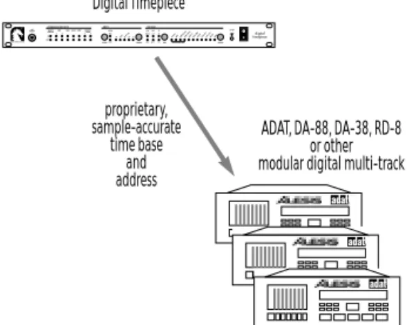
ADATs and DA-88s have their own proprietary synchronization format, which is supported directly by the Digital Timepiece. MDMs from other manufacturers have, in some cases, adopted either the Alesis or Tascam sync format. One example is the Fostex RD-8. The RD-8 has adopted the Alesis ADAT sync format and, as a result, can be connected directly to the Digital Timepiece in the same fashion as an ADAT. Check with the manufacturer of your device for compatibility. Modular digital multi-track systems have their own means of chaining multiple units and synchronizing them with single-sample accuracy to form, in effect, one large system that functions as a whole. The Digital Timepiece synchronizes multiple unit systems just as easily and effectively as a single unit. In fact, the connections and procedures for the Digital Timepiece are the same for single- and multiple-unit systems. The Digital Timepiece can even sync ADATs and DA-88s with each other with single-sample accuracy.
Modular digital multi-tracks also provide a way to synchronize to SMPTE time code. For example, ADATs and ADAT XTs require an Alesis BRC to synchronize to SMPTE or to follow MMC
other MMC controller). The Digital Timepiece has many of the same capabilities as a BRC, making it unnecessary for basic synchronization and MMC remote control of ADATs. The Tascam DA-88 synchronizes with other devices via an SY-88 add-on card. See “ABS time versus SMPTE offset with an SY-88” on page 18 for details.
How proprietary synchronization works
ADATs, DA-88s and any other devices that support the ADAT or DA-88 proprietary sync protocols are connected directly to the Digital Timepiece via the ADAT and DA-88 Sync ports. This connection provides both a sample-accurate time base and frame-accurate address information (Figure 3-6). In addition, the multi-track recorders to be either master of or slave to the Digital Timepiece.
Figure 3-6: How modular digital multi-track recorders like the ADAT, DA-88, DA-38 and RD-8 synchronize with the Digital Timepiece.
Refer to the sections below for specific information about each device, including important consider-ations if you are also using an Alesis BRC or Tascam SY-88 sync card.
New MDM systems are frequently being introduced. If you have a device other than the ones discussed in the following sections, contact Mark of the Unicorn technical support as described in “Technical Support” on page 98.
Digital Timepiece proprietary, sample-accurate time base and address
ADAT, DA-88, DA-38, RD-8 or other modular digital multi-track
Connecting ADATs as slaves
In most circumstances, you will want the Digital Timepiece to be the sync master over your ADAT(s). If so, connect the Digital Timepiece’s ADAT Sync Out port to the Sync In of your first ADAT using the sync cable supplied with the ADAT as shown in Figure 3-7. Don’t worry about setting the ADAT device ID: the Digital Timepiece sets it automatically.
Figure 3-7: Connecting an ADAT as a slave to the Digital Timepiece.
If you have several ADATs, you can chain the rest of them to the first one as shown in Figure 3-8.
Figure 3-8: Connecting multiple ADATs.
Connecting the Digital Timepiece as a slave
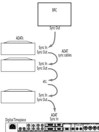
If you have an Alesis BRC, and you want to use it as your master control surface, you will need to connect the Digital Timepiece as the last device in your ADAT chain, as shown below in Figure 3-9, with the BRC as the master of the chain.
Figure 3-9: Connecting a slaved Digital Timepiece as the last device in an ADAT chain.
ADAT sync cable Digital Timepiece ADAT Sync In port ADAT Sync Out ADATs Digital Timepiece Sync In ADAT sync cables Sync Out Sync In Sync Out Sync In Sync Out etc. ADAT Sync Out port
Digital Timepiece BRC ADAT Sync In Sync Out ADATs Sync In ADAT sync cables Sync Out Sync In Sync Out Sync In Sync Out etc.
WORKING WITH THE TASCAM DA-88 There are several ways to connect the DA-88 to the Digital Timepiece, depending on whether you are running the DA-88 under ABS time or SMPTE time (while under the control of a Tascam SY-88 sync card). The next section discusses ABS time versus SMPTE offset with an SY-88 card.
ABS time versus SMPTE offset with an SY-88
The Tascam DA-88 can measure time in two ways: ■ absolutetime (also called ABS time)
■ SMPTE time with an offset (start frame)
Absolute time is a measurement of actual elapsed time since the beginning of the tape, where the beginning of the recordable portion of the tape (immediately after the tape leader) is zero. The front panel of the DA-88 displays ABS time, as does the MMC/Sync window in the Digital Timepiece’s ClockWorks software. For example, if you start recording at the beginning of the tape and record for 20 minutes, the ABS time display on the front panel of the DA-88 would display approximately 0:20:00:00.
If your Tascam DA-88 has an SY-88 sync card installed inside, the SY-88 card provides you with the ability to stripe (record) SMPTE time code on a special “sub-code” track on the tape. Once a tape has been striped in this manner, the SY-88 card can then read the time code on sub-code track and generally play, locate, and otherwise cue the DA-88 according to the time code, rather than ABS time. For example, you could stripe the tape starting at a time other than zero — a common situation when working with audio for picture — such as one hour and five minutes (01:05:00:00). You can then choose the offset option on the front panel of the DA-88 to display SMPTE time instead of ABS time in the DA-88’s front-panel counter. If you then record for twenty minutes starting at the beginning of the tape, the DA-88 counter would read
Connecting a DA-88 as an ABS slave
This type of sync can be done without an SY-88 sync card. The Digital Timepiece controls the DA-88. For example, from your computer sequencer, you can shuttle the Digital Timepiece, which in turn controls the DA-88. In this scenario, the DA-88 operates under ABS time only.
If you need to reference the DA-88 and Digital Timepiece to an external time code source, use one of the SY-88 related scenarios described in the following sections.
This scenario provides sample-accurate sync between the DA-88 and the Digital Timepiece. When the Digital Timepiece has control over one or more DA-88s via the DA-88 sync connectors (using ABS time), it must cue in three-second intervals to maintain sample-accurate sync. For example, if you cue the Digital Timepiece to 5 minutes and 2 seconds from the transport controls in your sequencer, and then start playback, the Digital Timepiece (and all devices under its control) will begin playing at the nearest 3-second interval (5 minutes, 3 seconds in this example). If you are doing detailed work for which this three-second interval is not acceptable, use one of the SY-88-related sync scenarios described in the following sections.
In this scenario, connect the Digital Timepiece’s DA-88 Sync Out port to the Sync In of your first DA-88 using the sync cable supplied with the DA-88 as shown in Figure 3-10. If you have a single DA-88, make sure the device ID selector on the ‘System’ card on its rear panel is not set to zero. If you have a chain of DA-88s, make sure that none of them are set to zero, and also make sure that each unit has a unique ID setting.
Figure 3-10: Connecting a Tascam DA-88.
If you have several DA-88s, you can chain the rest of them to the first one as shown in Figure 3-11. Note that you can connect both ADATs and DA-88s at the same time (not pictured).
Figure 3-11: Connecting multiple DA-88s.
Connecting the Digital Timepiece as ABS slave
In this scenario, the DA-88 serves as the time base, address, and transport master. You control the Digital Timepiece, along with everything else attached to the Digital Timepiece, from the transport controls on the DA-88 itself. This scenario provides sample-accurate sync between the DA-88 and the Digital Timepiece.
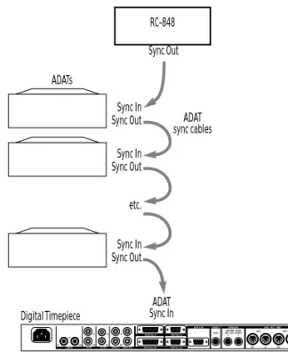
There may be some situations in which you want to slave the Digital Timepiece to your DA-88 instead of the other way around. For example, if you have a Tascam RC-848 controller, and you want to use it as your master control surface, you will need to connect the Digital Timepiece as the last device in your DA-88 chain, as shown below in Figure 3-9, with the 848 as the master of the chain.
Figure 3-12: Connecting a slaved Digital Timepiece as the last device in a DA-88 chain. In this example, the RC-848 is master of the chain.
Make sure you set the RC-848 ID to zero (0) so that it powers up as the master of the chain. Also make
DA-88 Sync In port DA-88 Sync Out Digital Timepiece
DA-88 sync cable Any device ID except 0
DA-88s Digital Timepiece Sync In DA-88 sync cables Sync Out Sync In Sync Out Sync In Sync Out etc. DA-88 Sync Out port
Device ID 1
Note: if you are using house sync, it should not be fed to the DA-88s in this scenario. House sync should be fed to the Digital Timepiece instead. Device ID 2 Device ID 3 Digital Timepiece RC-848 ADAT Sync In Sync Out ADATs Sync In ADAT sync cables Sync Out Sync In Sync Out Sync In Sync Out etc.
Using a DA-88 with an SY-88 sync card as the SMPTE time code master
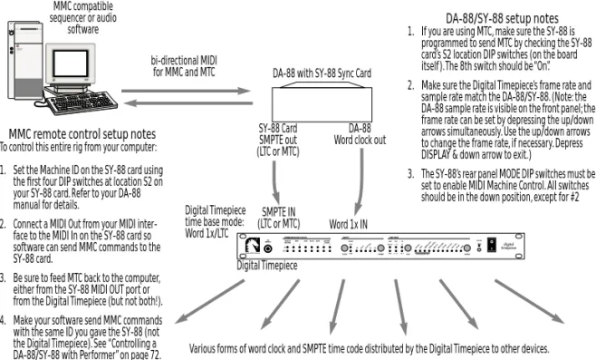
If you would like to use the SMPTE time code track on a DA-88 deck equipped with an SY-88 card, then the DA-88 cannot operate as a slave to the Digital Timepiece. Instead, the DA-88 acts as the master and the Digital Timepiece slaves to it, a shown below in Figure 3-13. The word clock connection from the SY-88 card to the Digital Timepiece is optional, although it is highly recommended for tighter sync and faster lockup time.
This scenario requires an SY-88 card. The DA-88/ SY-88 combination serves as the master, feeding SMPTE time code (LTC or MTC) to the Digital Timepiece and other devices. You control the Digital Timepiece, along with everything else attached to the Digital Timepiece, from the DA-88. This scenario allows you to sync the DA-88 — and
the Digital Timepiece — to time code from other sources, such as a video deck, or the time code sub-track on a DA-88 tape.
DA-88/SY-88 as SMPTE and word clock master
This scenario is identical to the SMPTE-only scenario just discussed, except that you also feed word clock from the SY-88 card into the Digital Timepiece, in addition to SMPTE time code, as shown below in Figure 3-13. This produces faster lock-up times and tighter sync than the SMPTE-only scenario above.
Figure 3-13: To use the time code track on a DA-88 equipped with an SY-88 sync card, the DA-88 serves as the time code master. In this setup, it also serves as the time base master. The Digital Timepiece slaves to the word clock and SMPTE it receives from the DA-88. The MMC remote
Digital Timepiece
DA-88 with SY-88 Sync Card
DA-88 Word clock out
Word 1x IN SMPTE IN (LTC or MTC) SY-88 Card SMPTE out (LTC or MTC) Digital Timepiece time base mode: Word 1x/LTC MMC compatible sequencer or audio software bi-directional MIDI for MMC and MTC
Various forms of word clock and SMPTE time code distributed by the Digital Timepiece to other devices.
DA-88/SY-88 setup notes
1. If you are using MTC, make sure the SY-88 is programmed to send MTC by checking the SY-88 card’s S2 location DIP switches (on the board itself). The 8th switch should be “On”. 2. Make sure the Digital Timepiece’s frame rate and
sample rate match the DA-88/SY-88. (Note: the DA-88 sample rate is visible on the front panel; the frame rate can be set by depressing the up/down arrows simultaneously. Use the up/down arrows to change the frame rate, if necessary. Depress DISPLAY & down arrow to exit.)
3. The SY-88’s rear panel MODE DIP switches must be set to enable MIDI Machine Control. All switches should be in the down position, except for #2
MMC remote control setup notes
To control this entire rig from your computer: 1. Set the Machine ID on the SY-88 card using
the first four DIP switches at location S2 on your SY-88 card. Refer to your DA-88 manual for details.
2. Connect a MIDI Out from your MIDI inter-face to the MIDI In on the SY-88 card so software can send MMC commands to the SY-88 card.
3. Be sure to feed MTC back to the computer, either from the SY-88 MIDI OUT port or from the Digital Timepiece (but not both!). 4. Make your software send MMC commands with the same ID you gave the SY-88 (not the Digital Timepiece). See “Controlling a DA-88/SY-88 with Performer” on page 72.
Using house sync with the Digital Timepiece and a DA-88/SY-88 (“Triple-sync”)
If you would like to use the SMPTE “sub code” track on a DA-88 equipped with an SY-88 card as the master address source for your rig, and you would also like to use house sync video as a timebase for everything, connect the DA-88 to the Digital Timepiece as shown below in Figure 3-14. In this setup, both the SY-88 card and the Digital Timepiece resolve to house sync. In addition, the Digital Timepiece resolves to the word clock generated by the SY-88 card. The SY-88 card serves as the time code address master source.
This scenario is identical to the one on the previous page (Figure 3-13), except for the video feed to both the DA-88 and the Digital Timepiece. Of all the SY-88-related (non-ABS) sync scenarios, this one produces the tightest lock-up between the Digital Timepiece and the DA-88.
You can control the transports of the entire rig (via the SY-88 card) from one of several possible transport control sources:
■ The transport buttons on the front panel of the DA-88
■ An RC-848 controller connected to the DA-88 ■ Computer software that has been set up to control the SY-88 card via MIDI Machine Control Because the Digital Timepiece is so flexible, you can use various sources for time code, video, and word clock. For example, you could feed SMPTE to the SY-88 card and Digital Timepiece from a video deck that is also referenced to house video, such that the video deck is the transport/address master.
Controlling a DA-88/SY-88 from Performer
You can trigger the entire rig shown in Figure 3-13 or Figure 3-14 from Performer. For step-by-step directions, see “Controlling a DA-88/SY-88 with Performer” on page 72.
Digital Timepiece DA-88 with SY-88 Sync Card
DA-88 Word clock out
Word 1x IN SMPTE IN (LTC or MTC) SY-88 Card SMPTE out (LTC or MTC) Digital Timepiece time base mode: Word 1x/video/LTC or Word 1x/video/MTC House Sync Video Generator Video Sync In Video IN MMC compatible sequencer or audio
software bi-directional MIDI for MMC and MTC
Various forms of word clock and SMPTE time code distributed by the Digital Timepiece to other devices. Check the DA-88/SY-88 setup notes in
Figure 3-13 for additional important info.
Check the MMC remote control setup notes in Figure 3-13 for additional important info.
WORD CLOCK DEVICES
Word clock is a timing reference for digital audio devices. Word clock supplies common timing to multiple devices so that they can be synchronized with one another. We call a device that supports word clock — i.e. it has word clock connectors on it — as a word clock device. Here are a few examples:
■ Digital mixers
■ Stand-alone hard disk recorders
■ Computer-based digital audio workstations ■ Computer audio cards
The Digital Timepiece supports two different word clock formats: Word 1x and Word 256x. Word 1x is an industry standard format and is supported by all devices except several systems made by Digidesign. Digidesign systems have their own word clock format, Word 256x, which they refer to as superclock, slave clock or word 256x. Always connect Digidesign hardware to the WORD 256x connectors on the Digital Timepiece. Connect all other word clock devices to the WORD 1x connectors.
How it works
When synchronizing two word clock devices, one acts as the master and the other serves as a slave. The slaved device follows the master to maintain sample-accurate synchronization.
Word clock is a time base reference only, providing an accurate measurement of the passage of time and the speed at which samples should go by. Word clock carries no address (time code) information (e.g. “we’re at 1:05:33:14”). Therefore, word clock by itself is not enough to synchronize two devices. Time code is also required so that each device knows where to go in time when you tell it to cue, play, record, stop and chase. An example is shown below in Figure 3-15.
Figure 3-15: How word clock devices synchronize with the Digital Timepiece. In this example, the Digital Timepiece is both the word clock (time base) master and address (time code) master.
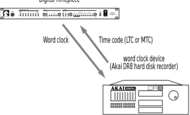
Interestingly, though, the word clock master device does not necessarily have to be the address master. A word clock slave can be an address master, while the word clock master provides the overall time base. In the example shown in Figure 3-16, the Digital Timepiece is the word clock master, while the Akai DR8 hard disk recorder is the time code master. This setup would allow you to control the transports of everything from the DR8 front panel (or a transport control surface connected to the DR8).
Figure 3-16: In this example, the Digital Timepiece is the word clock (time base) master and the Akai DR8 hard disk recorder is the address (time code) master. This allows you to synchronize the DR8 with other digital audio devices connected to the Digital Timepiece, while at the same time controlling the transports of everything from the DR8 (or a control surface connected to the DR8).
Digital Timepiece
Word clock
word clock device Yamaha 02R digital mixer Time code (LTC or MTC)
word clock device (Akai DR8 hard disk recorder) Digital Timepiece
Connecting a word clock device as slave
In most situations, you’ll want to connect your word clock device as a slave to the Digital Timepiece as shown below in Figure 3-17.
Figure 3-17: Connecting a word clock device. In this example, SMPTE time code is being fed to the word clock slave device via the Digital Timepiece’s LTC SMPTE output. Alternately, you could feed MIDI Time Code (MTC) from the Digital Timepiece’s MIDI OUT.
Connecting multiple word clock devices
If you have more than one word clock device, there are several possibilities for connecting them to the Digital Timepiece. First, the Digital Timepiece actually provides two word clock outputs: a WORD 1x OUT and a WORD 256x OUT, and it is possible to use both at the same time. For example, you could connect a stand-alone hard disk recorder to the word 1x output and a Digidesign Pro Tools™ system to the word 256x output. (Just remember, only Digidesign hardware will work with the 256x output.)
But what if you already have a device connected to the 1x word clock output, such as a hard disk recorder, and you’d like to connect a second word clock device, such as a digital mixer? In this scenario, you can try chaining the second device to the first, connecting the word clock output of the first to the word clock input of the second. Keep in mind, however, that some devices don’t support this very well. For best results, try to keep the cable lengths as short as possible.
SMPTE IN Word clock device
word 1x OUT Digital Timepiece SMPTE OUT word clock IN
S/PDIF DEVICES
S/PDIF is an industry standard format for transferring stereo digital audio from one device to another. While many devices on the market support S/PDIF, the term S/PDIF device as used in this discussion refers to a device that has no other way of synchronizing digitally with other devices. Examples of this kind of device are:
■ Digidesign Audiomedia I, II and III cards ■ DAT decks
Devices that have S/PDIF connectors, but also have word clock connectors, ADAT sync connectors, or other means of digital audio synchronization, should be incorporated into a Digital Timepiece system using these other sync formats.
How S/PDIF sync works
When synchronizing two S/PDIF devices, one acts as the master and the other serves as a slave. The slaved device follows the master to maintain accurate synchronization that won’t drift. S/PDIF is similar to word clock in the sense that it is a time base reference, providing an accurate measurement of the passage of time and the speed at which samples should go by. S/PDIF can also contain embedded address information (e.g. “we’re at 1:05:33:14”). However, many S/PDIF devices, including most DAT decks, do not support embedded time code. In order to support as wide a range of devices as possible, the Digital Timepiece does not support embedded S/PDIF time code either. Instead, it uses the S/P DIF sample clock as a time base and relies on time code (SMPTE time code or MIDI time code) to make the S/P DIF device chase, locate and play in sync with the Digital Timepiece. An example is shown in Figure 3-22 on page 26.
S/PDIF devices cannot be chained.
S/PDIF thru
S/PDIF differs from word clock because it is not just a synchronization format: it consists of actual digital audio signal, which can be recorded from one device to another. As a result, the Digital Timepiece has a S/PDIF THRU button on the front panel that allows the Digital Timepiece to become transparent and pass any audio signal it receives on its S/PDIF IN port directly to its S/PDIF OUT port. When the THRU button is pushed out, the Digital Timepiece “swallows” incoming S/PDIF signal. If the Digital Timepiece is currently set to its S/PDIF time base mode, it will also slave to the S/P DIF signal that it swallows. When the THRU button is pushed in, the THRU LED on the front panel lights up and the Digital Timepiece ignores whatever it receives on its S/PDIF input, passing the signal through, unaltered, to its S/PDIF output as shown in Figure 3-18. The Digital Timepiece cannot slave to S/PDIF input when S/PDIF THRU is engaged. This feature is supplied as a convenience, so you don’t have to swap cables for different situations. If you want to slave the Digital Timepiece to an S/ PDIF device, release the THRU button. If you want to pass the device’s S/PDIF signal to another device connected to the Digital Timepiece’s S/PDIF Out, push the THRU button in.
Figure 3-18: An example of bidirectional communication between two S/PDIF devices. When Digital Timepiece’s S/PDIF THRU button is
S/PDIF device A S/PDIF Out
S/PDIF In Digital Timepiece
S/PDIF In
S/PDIF device B
S/PDIF Out S/PDIF In
S/PDIF Out S/PDIF THRU
turned on (button pushed in)
S/PDIF THRU button is pushed out (off ), the Digital Timepiece “swallows” the signal from Device A. The Digital Timepiece can slave to Device A only when THRU is turned off.
Connecting S/PDIF devices
The S/PDIF connections you make to the Digital Timepiece depend on what devices you have. Here are a few examples.
Figure 3-19: Connecting a single S/PDIF device to the Digital Timepiece.
If you have S/PDIF device, such as an Audiomedia card, and another device that is slaved to the Digital Timepiece, such as an ADAT or DA-88, and you would like to do S/PDIF transfers between them, you would need to connect them like this.
Figure 3-20: Connecting an Audiomedia card bidirectionally with a DA-88 via the Digital Timepiece. The Digital Timepiece is the word clock and time code master. When recording from DA-88 to Audio-media, engage S/PDIF THRU on the Digital Timepiece front panel (push it in). When recording from Audiomedia to DA-88, disengage S/ PDIF THRU (push it out). This same scenario could be used for ADAT (with an Alesis AI-1 converter, which connects optically to ADAT).
If you have two S/PDIF devices, you can connect them as shown in Figure 3-18 on page 24. But only Device B can be slaved digitally (via S/PDIF) to the Digital Timepiece.
Example: Digidesign’s Audiomedia card
Digidesign’s Audiomedia card serves as a useful example for how you can use the Digital Timepiece’s S/PDIF synchronization capabilities. The Digital Timepiece’s S/PDIF sync feature helps solve two problems for Audiomedia™ I, II or III users: drift and digital transfers to and from ADAT and other systems.
The drift problem
The first problem is drift. If you have an
Audiomedia card, you are probably running it with a digital audio sequencer or a Digidesign software package like Pro Tools™ or Session™. But you have probably discovered that when you are slaving the software to external time code, long portions of audio (i.e.audio regions that are longer than a minute or so) can drift out of sync with time code. This is because the Audiomedia card triggers
regions at the proper time during playback, but once they start, they’re on their own, playing at a rate determined by the Audiomedia card’s own internal clock. Because the Audiomedia card’s clock is not resolved to external time code, the audio inevitably drifts over time. To address this problem, most Audiomedia-compatible programs offer a software synchronization feature, where the software slaves to external time code and then drives the Audiomedia hardware. But this feature is undesirable because it actually adds or removes samples as needed to stay in sync with external time code — not exactly a high-fidelity solution. Another work-around is to chop lengthy audio regions into small pieces — not exactly convenient.
S/PDIF In S/PDIF Out
S/PDIF device Digital Timepiece
S/PDIF In S/PDIF Out
TDIF-1 I/O Audiomedia Sync mode: Digital S/PDIF Out S/PDIF In IF-88AE converter DA-88
Digital Timepiece (Internal mode)
S/PDIF Out S/PDIF In S/PDIF Out S/PDIF In DA-88 Sync Out DA-88 Sync In