Tracking and Identifying Burglar using
Collaborative Sensor-Camera Networks
Haitao Zhang
†, Shaojie Tang
‡, Xiang-Yang Li
§,‡, and Huadong Ma
††Beijing Key Lab of Intelligent Telecomm. Software and Multimedia, Beijing University of Posts and Telecomm., Beijing, China
‡Dept. of Computer Science, Illinois Institute of Technology, Chicago, USA §Tsinghua National Laboratory of Information Science and Technology,
Tsinghua University, Beijing, China
Email: [email protected]; [email protected]; [email protected]; [email protected]
Abstract—This work presents BurTrap, a networking system which integrates wireless modules (such as TelosB nodes) with networked surveillance cameras to automatically, accurately, timely track and identify burglar who stole the property. First, we design an energy-efficient wakeup scheduling protocol that guarantees a successful target tracking while reducing the com-munication energy consumption of the portable wireless module. Then, we identify burglar among all the objects appeared in the obtained video information by performing trajectory fitting between the estimated geometric trajectory and the estimated local visual trajectory. Through extensive experiments, we show that BurTrap can pinpoint the burglar with extremely high accuracy.
I. INTRODUCTION
Many different systems have been proposed and used in practice to enhance the security and protection of the property. Traditional home security systems deter or detect burglary through increased surveillance (cameras, motion detectors, and alarm systems), but they cannot help track or recover property once it is stolen.
For tracking and recovering stolen vehicles, LoJack [2] may be the most common system for this purpose. The core of the LoJack Stolen Vehicle Recovery System is a small, silent radio transceiver that is clandestinely installed in a vehicle. Once a car with LoJack device is reported to be stolen, the device will be activated and then transmit periodic beacons that can be received by the LoJack receivers which is used by police. Asset tracking products like Brickhouse [3] and Liveview [4] use GPS to obtain realtime location information of the protected property and use cellular infrastructure to communicate the data to the control center. Recently, Guhaet al.[5] presented AutoWitness system to deter, detect, and track personal property theft. Their novel system uses accelerometer and the RF signal from cellular tower to compute the moving trajectory of the target. All these systems focus on tracking the stolen property. We point out that knowing the trajectory of a property does not mean that we can recover the property easily. Moreover, these tracking systems do not provide any physical traits of the burglar.
On the other hand, the widely used secure monitoring approach is to install security surveillance cameras at public places. These surveillance cameras can only record the objects
(e.g., a car, or a person) that appeared inside the view of the camera, however it cannot detect whether an object does carry a stolen property, which may not be visible from the surveillance camera. Currently, these surveillance tasks are accomplished by human operators who continuously observe monitors to detect unauthorized abnormal activities over many cameras.
In this paper, we first construct a full autonomous networked surveillance framework BurTrap that integrates wireless mod-ules with surveillance camera networks. The wireless modmod-ules, which are TelosB nodes in our system, collaborate with the networked cameras to automatically, accurately, timely track and identify burglars. For prolonging the lifetime of the portable wireless module, we then propose an energy-efficient wakeup scheduling protocol that guarantees the successful target tracking while reducing the communication energy consumption of the portable wireless module. Third, we propose a novel target identification approach by performing trajectory fitting between the geometric trajectory and the visual trajectory of the target. Finally, we conduct the extensive experiments, and the experiment results show that our system can achieve the extremely high target identification accuracy. The rest of this paper is organized as follows. In Section II, we present the overview of BurTrap system. We then present an adaptive wakeup scheduling for the portable wireless module in Section III. The burglar identification approach is proposed in Section IV. Section V shows the experimental results. We conclude the paper in Section VI.
II. SYSTEMOVERVIEW
BurTrap consists of three major components: the networked sensor-camera mates, the portable wireless module installed in the protected property, and the monitoring center. Each sensor-camera mate, which is taken as a surveillance point, is equipped with a camera and a site wireless module. Once the burglar who carries the stolen property passes by a surveillance point, the alarm signal periodically sent from the portable wireless module can be received by the site wireless module, and then the corresponding camera is activated for capturing the visual information which contains the burglar with high possibility. In addition, the spatial-temporal information of the
burglar travel trajectory is also recorded by the surveillance point simultaneously. After gathering the sensing information from the sensor-camera network, the monitoring center tracks and identifies the burglar by analyzing and fusing the multi-modal sensing information.
Before presenting the basic idea of identifying the burglar, we give two trajectory definitions.
Definition 1: Geometric Trajectory is the approximate burglar travel trajectory which is estimated based on the tra-jectory spatial-temporal information collected by site wireless modules.
Definition 2: Local Visual Trajectory is the approximate object trajectory which is piecewise linear and is estimated based on the visual information collected by a single camera. Note that there usually exist multiple objects in a video sequence of a single camera and each of the objects has its own local visual trajectory in this situation.
The basic idea of identifying the burglar is as follows. Every object which appears in the recorded visual information has its own trajectory fitting difference between the geometric trajectory and its local visual trajectory. If the similarity between the geometric trajectory and the local visual trajectory of an object is high, the value of the fitting difference of the two trajectories is small. First, the fitting difference of an object is calculated based on the sensing information from a single surveillance point. Then, the fitting difference is recalculated by matching the objects which appear in the visual information from multiple cameras. The object with the minimum fitting difference is treated as the burglar intuitively. More specifically, BurTrap system has the following main tracking and identifying operations.
Wakeup Scheduling of Portable Wireless Module for Tracking Information Retrieval: If a protected property has been stolen, the portable wireless module can be triggered according to some triggering scheme [6], and periodically broadcast the alarm messages. Once the protected property has entered the communication range of some site wireless mod-ule, the alarm messages will be received by the site wireless module. For saving the broadcast communication energy, we design a wakeup scheduling protocol for the portable wireless module.
Tracking Information Retrieval using Networked Sensor-Camera Mates: Upon receiving the alarm messages, the site wireless module activates the associated camera to capture the critical video frames, and the video capturing process continues until the property leaves the communication range of the site wireless module. Moreover, when receiving the alarm message, the site wireless module immediately records the current time and its position as the spatial-temporal information of the burglar travel trajectory.
Geometric trajectory estimation: The monitoring center collects the spatial-temporal information of burglar travel trajectory, and estimate the geometric trajectory based on the collected data. Consider a sensor-camera mate network in a two-dimensional plane. The location of each surveillance point is known. When a target burglar passes through the
communication region of a surveillance point, the site wireless module associated with this surveillance point will receive some alarm messages sent from the portable wireless module fixed in the stolen property, and the current time and one bit of information about the appearance of the burglar are recorded. This sensing model for geometric trajectory information is the same as the binary sensing model [7] [8].
For estimating the geometric trajectory, we employ a parti-cle filtering algorithm [7] [8] in which a cost function is used to penalize changes in velocity. The final output is simply the particle with the best cost function. The estimated geometric trajectory is the piecewise linear trajectory that traverses all the communication regions by connecting the obtained particles in order.
Local visual trajectory estimation:The camera captures the image frames during the interval in which the site wire-less module continuously receives the alarm messages from the portable wireless module. Therefore, the captured video sequence, which will be transmitted and recorded by the mon-itoring center, may contain the burglar. For every incoming video sequence from a camera, the monitoring center first needs to find a set of objects (in our experiments, a set of different human beings) that appear in this video sequence by using the background subtraction technique [9]. Then, the object feature, which is the color histogram in this paper, is calculated and is used as the object matching metric of finding the same object that appears in the video sequences from the different cameras.
For estimating the visual trajectory of objects in a single camera’s scene, a projective operation is used to map the camera platform’s points into a Euclidean coordinate system within a plane, typically the ground plane, in the scene. Assume the coordinate of a point in the image plane is x and the 3D coordinate of the corresponding point in the scene is X. The pair of corresponding points on the two planes is related projectively by an homographyX =M ·xwhereM is the3×3transformation matrix . The transformation matrix M can be recovered by using the techniques proposed in [10].
Burglar identification using trajectory fitting:After esti-mating the geometric trajectory and the local visual trajectory of each object, we identify the burglar among all the objects that appear in the recorded video sequences based on a well-designed trajectory fitting metric.
III. ADAPTIVEWAKEUPSCHEDULING OFPORTABLE
WIRELESSMODULE
The wakeup scheduling protocol of the portable wireless module is an adaptive duty cycle protocol and each cycle is divided into two periods: wakeup period and sleep period. Once the portable wireless module is triggered to report the alarm messages, it runs according to the wakeup scheduling protocol. In the beginning of each wakeup period, the portable wireless module broadcasts the alarm message once, and then waits to receive the ACK message from some site wireless module. Once the portable wireless module receives an ACK message, it goes into the sleep period in which the portable
wireless module turns off its radio for saving energy. If the portable wireless module does not receive any ACK message before a deadline which is set to the end of the cycle period, it goes into the next cycle period and broadcasts an alarm message. When a site wireless module receives an alarm message, it will broadcast an ACK message immediately.
In our BurTrap system, when a burglar passes through the communication region of a site wireless module, the camera associated with the site wireless module is activated to capture the critical video frames which may contain the burglar. The burglar appearing interval estimation is based on the broadcasting period of the alarm messages. The smaller the alarm message broadcasting period is, the more accurately we estimate the burglar appearing interval. This means that the portable wireless module needs to consume more energy of sending the alarm messages. Therefore, there is a trade-off between the communication energy consumption of the portable wireless module and the probability of the captured video information containing the burglar.
Let pc be the cycle period. Assume the interval of the burglar appearing in the communication region of site wireless module iisTi= [Tis, Tie]. Lettsi be the first time of module i receiving the alarm message and te
i be the last time of moduleireceiving the alarm message. We estimateTithrough setting Tis =tsi and Tie=tei. The problem description is as follows. Given the sensor-camera network and the trajectory of the burglar, how to dynamically adjust the wakeup time of the portable wireless module so that each interval Ti can be estimated with a maximum errorεmaxand the alarm messages are broadcasted as little as possible.
Apparently, we have εmax<2pc. For controlling the esti-mation error, we set the cycle period pc to 12εmax. However, the energy efficiency of the portable wireless module is low if the required estimation error is small. In fact, lots of alarm messages are not useful for ensuring the estimation accuracy of Ti, and our object is to find and cancel these useless alarm messages. Assume tws
i and twei are respectively the first and the last starting time of wakeup periods within Ti. It is obvious that the wakeup periods between tws
i and twei have no effect on the accuracy of estimatingTi. Based on our experimental study, we find thatTi is quite similar withTj if the burglar passes through the sensing regions of cameraiand j. Assume the burglar has passed through the communication regions of site wireless modules 1,2, ..., k. For the portable wireless module, let ris be the first time of receiving module i’s ACK message andrei be the last time of receiving module i’s ACK message. The portable wireless module can estimate the average of Ti by using Tb = 1k
Pk i=1(r e i −r s i). Because there is a difference between Tb andTi, the portable wireless module cannot know the useless wakeup periods exactly. Our adaptive wakeup scheduling scheme works as follows. When the portable wireless module receives the first ACK message from site wireless module i at time ts
i, it begins to cancel the wakeup period with some probability. The cancelling probability of the wakeup period follows Gaussian distribution whose expectation and variance are respectively ts
i + 1 2Tband (Tb 2) 2.
IV. BURGLARIDENTIFICATION USINGTRAJECTORY
FITTING
A. Fitting Metric
We use the local visual trajectory which is piecewise linear for trajectory fitting. The local visual trajectory of the objecti is estimated as follows. For a sequence of video frames from the cameraCamh, we define the video frame set that contains the objectiasSi. An objectj, which has appeared in another video frame setSj (SiTSj=∅) captured by cameraCamh, is considered as a different object from i, namely i6=j. We selectq+1video frames fromSiin every equal interval (where qis 3 in this paper), and obtain a video frame sequenceSi0 =
{fi(0), ..., fi(q)}. The centroid positions of the object i in video framesS0iare respectively defined asyi(0), ..., yi(q). We transform the positionsyi(0), ..., yi(q)in the video frames into the global coordinatesYi(0), ..., Yi(q)by using the coordinate transforming method introduced in section II. We connect each pair of points−Y−−−−−−i(0)Yi(1)→,...,
−−−−−−−−−−→
Yi(q−1)Yi(q), and then obtainq connected directed line segments li(1), ..., li(q) which form the local visual trajectory of the objecti.
The geometric trajectory L characterizes the global travel feature of the burglar. For correctly fitting with the local visual trajectoryli(1), ..., li(q)of the objecti, we should extract the local travel feature of the geometric trajectory which associates with the sensing region of the camera Camh. Assume the time interval of the burglar traveling through the communi-cation region of the site wireless module Senh is [ts, te]. From the particle filtering estimation precess of the geometric trajectory, we know there existp−1calculated best particles x(t1), ..., x(tp−1)where ts≤t1 ≤... ≤tp−1 ≤te. We con-nect each pair of points−x−−−−−−−−−(t1−1)x(t→1),...,
−−−−−−−−−−−−−→ x(tp−1)x(tp−1+ 1)
in the point sequencex(t1−1), x(t1), ..., x(tp−1), x(tp−1+1),
and then obtainpconnected directed line segmentsL1, ..., Lp which is actually the local geometric trajectory associated with the sensing region of the cameraCamh.
Assume φh
i(k)(m) (≥0) is the angle between the two di-rected line segmentslkandLm(k= 1, ..., q;m= 1, ..., p). We define the fitting difference between the geometric trajectory and the local visual trajectory of the object iin the scene of the cameraCamh as
φhi = 1 q·p q X k=1 p X m=1 φhi(k)(m) (1) B. Burglar Identification using Trajectory Fitting
Assume BurTrap has recorded N critical video sequences S1, ..., SN in order which contain the burglar with high probability when the burglar passes through the surveillance region of the sensor-camera network. We define thej-th object appeared in the i-th video sequence Si as Oi,j. Assume the number of people that appear in Si is Mi (i= 1, ..., N). We aim to quickly and accurately identify the burglar among those objects Oi,j (i= 1, ..., N;j= 1, ..., Mi).
The basic assumption behind the above burglar identifi-cation problem is that the burglar exists in the objects Oi,j (i= 1, ..., N;j= 1, ..., Mi). Based on the BurTrap operating mode introduced previously, this is reasonable when there are the sufficient number of the sensor-camera mates that have detected the burglar. To find the burglar, we evaluate the fitting difference between the geometric trajectory Land the local visual trajectory of object Oi,j, which is defined asφi,j (i= 1, ..., N;j= 1, ..., Mi).
First, we group all the objects Oi,j (i = 1, ..., N;j =
1, ..., Mi) according to i and select the more suspicious objects. In our system, if the fitting difference φi,j is greater than 90, we think the dissimilarity between the trajectories of the burglar and the object Oi,j is so large that the probability of the objectOi,j being the burglar is very low. Therefore, we delete the objects whose φi,j > 90 from each object group, and the remaining object set of group iis defined asΘi.
Then, we sort objects in each object set Θi by the as-cending order of the fitting difference of the objects, and obtain a ordered sequence of the objects Oi,j1, ..., Oi,jk with
φi,j1 ≤ · · · ≤ φi,jk. In the object set Θi, the burglar
identi-fication principle is that the object with minimum trajectory fitting difference is considered as the most suspicious object. However, this principle may not be correct in a single sensor-camera mate scene because there may exist multiple objects that have similar moving trajectory in a single sensor-camera mate scene or there is a mismatch between the communication region of the wireless module and the camera sensing region. For accurately identifying the burglar, we further fuse the trajectory fitting difference of the same object that appears in the multiple sensor-camera mate scenes by performing inter camera appearance matching. Before fusing the local visual trajectory information in the multiple camera scenes, we need to verify if the currently observed objects in a camera scene are indeed the same as the ones being tracked in other camera scenes. The common method to match object appearances is by estimating the similarity between the color histograms of objects. We evaluate the similarity between couple of color histograms by using the well known Bhattacharyya distance. The Bhattacharyya distance is defined as
DB(p, q) =−ln " X x∈X p p(x)·q(x) # (2)
where pandq are two discrete probability distributions over the same domain X, respectively. The object matches are
carried out choosing those that produce the lowest value of the Bhattacharyya distance between the color histograms of the considered objects in one camera with all the possible objects that have traveled through another camera. If the minimum Bhattacharyya distance is less than a given threshold, we think the two objects are the same one and update the trajectory fitting difference of the object. The threshold can be selected by measuring the mean values of the Bhattacharyya distances among the couples of the samples of the same person in the two fields of view. The burglar identification algorithm is given
in Algorithm 1.
Algorithm 1 Burglar identification algorithm.
Input: Ordered object sets Θi (i = 1, ..., N), trajectory fitting
difference φi,jk and mean color histogram Hi,jk of object
Oi,jk(∈Θi), ordered result object setΘwhich is set to empty
initially, a given thresholdd0.
Output: The first object inΘ(ifΘis not empty).
1: Θ←Θ1,i←2.
2: whilei≤N do
3: forEach objectOi,jk∈Θi do
4: forEach objectO0∈Θdo
5: Calculate Bhattacharyya distanced(Oi,jk, O
0
) between
ˆ
Hi,jk and the color histogram ofO0.
6: O˜←arg minO0∈Θ(d(Oi,jk, O0)).
7: ifd(Oi,jk,O˜)≤d0then
8: Update trajectory fitting differenceφ˜ofO˜by usingφ˜←
i−1
i φ˜+
1
iφi,jk.
9: else
10: Insert objectOi,jk intoΘwhile keeping the ascending
order of trajectory fitting difference.
11: i←i+ 1.
V. EXPERIMENTALRESULTS
A. Experiment Setup
1) BurTrap Implementation: In our experiments, one laptop connected with one sensor node and one camera is taken as one sensor-camera mate unit. In this sensor-camera mate unit, the sensor node component is the TelosB node [12]. The sensor program is developed based on TinyOS 2.1. The proposed adaptive wakeup scheduling protocol is implemented by using nesC language. The maximum estimation errorεmax is set to 500ms. In our experiments, we set the transmission power of each TelosB node to level 5 through the TinyOS interface. The video processing algorithm was carried out on the platform of VC++ .NET 2005 combined with OpenCV (the open source computer vision library supported by Intel Corporation). Fig. 1 shows the deployment situation of the networked sensor-camera mates.
B. Experimental Results
1) Test I: Robustness to inconsistency between commu-nication region of wireless modules and sensing region of cameras: In Test I, the trajectory of the burglar is depicted in Fig. 1 by using the red curve. The estimated geometric trajectory is depicted using the blue piecewise linear segments. Fig. 1 also shows some video frames which are respectively selected from the saved video sequences captured by cameras 3, 4, and 5. In each video frame, the detected objects are indicated by the green rectangles. Each detected objects is tracked within the corresponding camera scene and assigned an unique tag number. The local visual trajectory of object 0 is depicted using the yellow directed linear segments in the figure. Because the communication region of a TelosB node is different from the sensing region of a camera, the extracted video sequence in the laptop may not contain the burglar in some situations. As shown in Fig. 1, the burglar
1 2 3 4 5 6 7 0 1 2 1 0 2 0 0 1 0 0 4 4 5 5 3 3 Travel trajectory
of burglar Geometric trajectory
Local visual trajectory of object 0 Sensor-camera mate Camera sensing region Wireless module communication region x
Fig. 1. Burglar travel trajectory, estimated geometric trajectory, estimated
local visual trajectory of object 0 and selected frames, respectively captured by cameras 3, 4, and 5 in Test I.
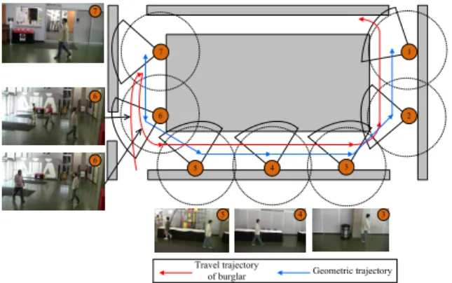
1 2 3 4 5 6 7 6 Travel trajectory
of burglar Geometric trajectory
0 1 2 0 1 0 6 6 7 0 0 1 00 5 4 3
Fig. 2. Burglar travel trajectory, estimated geometric trajectory, and selected
frames, respectively captured by cameras 3, 4, 5, 6, and 7 in Test II.
had passed through the communication region of site wireless module 6, but did not appear in the sensing region of camera 6. Therefore, there is a local estimation error of the geometric trajectory, and this leads to a large trajectory fitting difference of object 0. However, we can still take object 0 as the burglar through fusing the trajectory fitting differences associated with other sensor-camera mate scenes. This matches the ground truth.
2) Test II: Robustness to mismatch of objects appeared in different surveillance scenes: There are several factors that can lead to the mismatch of objects appeared in different surveillance scenes, e.g., features of objects, lighting condi-tions, and inaccurate background substraction. In Test II, the travel trajectory of the burglar and the estimated geometric trajectory are respectively depicted by using the red curve and the blue piecewise linear segments in Fig. 2. As shown in the figure, when the burglar (wearing the white clothes and blue pants) appeared in the communication region of site wireless module 7, a object that had a similar color feature with the burglar passed through the sensing region of camera 7, but the burglar had not entered into the sensing region of camera 7 yet. There had been an object mismatch between the scenes
of cameras 6 and 7 consequently, and we are not quite sure which object is the burglar only using the sensing information obtained from mates 6 and 7. However, we can still pinpoint the burglar successfully if we fuse more information from other sensor-camera mates, e.g., mates 3, 4, and 5.
VI. CONCLUSIONS
We present a novel networked surveillance system BurTrap for property recovery by using wireless sensor networks and digital cameras. BurTrap can not only track the burglar with the stolen property but more importantly identify the burglar automatically. We design an energy-efficient wakeup schedul-ing protocol for the accurate trajectory information retrieval while reducing the communication energy consumption of the portable wireless module. Further, the accurate automatic burglar identification is performed based on the proposed trajectory fitting technique.
ACKNOWLEDGMENT
The work of Haitao Zhang and Huadong Ma is supported by the National Basic Research Program of China (973 Pro-gram) under Grant No. 2011CB302701; The National Natural Science Foundation of China under Grant No. 60833009; China National Funds for Distinguished Young Scientists under Grant No. 60925010; the Funds for Creative Research Groups of China under Grant No.61121001. The work of Xiang-Yang Li and Shaojie Tang is partially supported by NSF CNS-0832120; NSF CNS-1035894; Program for Zhejiang Provincial Overseas High-Level Talents (One-hundred Talents Program).
REFERENCES
[1] F. UCR. Burglary - crime in the united states - 2008.
http://www.fbi.gov/ucr/cius2007/offenses/property crime/burglary.html. [2] Lojack. http://www.lojack.com/.
[3] Brickhouse security gps tracking system.
http://www.brickhousesecurity.com/gps-tracking-system.html. [4] Live view gps asset tracker.
http://www.liveviewgps.com/all+gps+tracking+products.html.
[5] S. Guha, K. Plarre, D. Lissner, S. Mitra, B. Krishna, P. Dutta, S. Kumar, “AutoWitness: Locating and Tracking Stolen Property While Tolerating
GPS and Radio Outages,”ACM SenSys’10, pp. 29-42, Nov. 2010.
[6] S. Tang, X.-Y. Li, H. Zhang, J. Han, G. Dai, X. Shen, “TelosCAM: Iden-tifying Burglar Through Networked Sensor-Camera Mates with Privacy
Protection,”IEEE RTSS, Nov. 2011.
[7] J. Singh, U. Madhow, R. Kumar, S. Suri, and R. Cagley, “Tracking
multiple targets using binary proximity sensors,”ACM/IEEE IPSN, pp.
529-538, Apr. 2007.
[8] N. Shrivastava, R. Mudumbai U. Madhow, and S. Suri, “Target Tracking with Binary Proximity Sensors: Fundamental Limits, Minimal
Descrip-tions, and Algorithms,”ACM SenSys’06, pp. 251-264, Nov. 2006.
[9] M. Casaresa, S. Velipasalar, and A. Pinto, “Light-weight salient
fore-ground detection for embedded smart cameras,” Computer Vision and
Image Understanding, vol 114, no. 11, pp. 1223-1237, Nov. 2010. [10] K. J. Bradshaw, I. D. Reid, and D. W. Murray, “The Active Recovery
of 3D Motion Trajectories and Their Use in Prediction,” IEEE Trans.
Pattern Anal. Mach. Intell., vol. 19, no. 3, pp. 219-234, Mar. 1997. [11] O. Javed, K. Shafique, and M. Shah, “Appearance modeling for Tracking
in Multiple Non-overlapping Cameras,”IEEE CVPR’05, vol. 2, pp. 26-33,
Jun. 2005.
[12] J. Polastre, R. Szewczyk, and D. Culler, “Telos: Enabling Ultra-Low