5. MICROPHONES AND LOUDSPEAKERS
A.A.N.M & V.V.R.S.R POLYTECHNIC GUDLAVALLERU Page 1 MICROPHONE:
It is an acoustic transducer that converts sound signal in to electrical signal. It converts variations in sound pressure in to low voltage electrical signal of same frequency and same phase.
Types of microphones:
Based On Output Impedance
1. Low Impedance Microphone
EX: Carbon Microphone, moving Coil Microphone. 2. High Impedance Microphone
EX: Crystal Microphone, Condenser Microphone. Based On The Directional Characteristics:
1. Omni Directional Microphone
Ex: Carbon Microphone, condenser Microphone, moving Coil Microphone and Crystal Microphone.
2. Bi- Directional Microphone EX: Ribbon Microphone.
3. Cardioid Microphone
Ex: Combination of Moving Coil and Crystal Microphone…,,,,....
• Based On Their Operation 1. Pressure operated microphones
EX: Carbon Microphone, Moving Coil Microphone, Condenser Microphone and Crystal Microphone.
2. Velocity operated microphones Ex: Ribbon Microphones.
5. MICROPHONES AND LOUDSPEAKERS
A.A.N.M & V.V.R.S.R POLYTECHNIC GUDLAVALLERU Page 2 CARBON MICROPHONE:
Principe:
It works on the principle of varying resistance of a small enclosure filled with carbon granules. The resistance of the enclosure varies linearly with the sound pressure variations. Hence it is pressure operated microphone.
Construction:
It consists of light, stiff and thin diaphragm made of duralumin and a brass cup filled with carbon granules. Two metal electrodes are placed in carbon granules in which one is fixed and the other is movable. The diaphragm is in contact with granules through movable electrode. A battery and a load is connected across two electrodes as shown in fig.
Working:
When sound waves strike the diaphragm it moves to and fro. During compression, the carbon granules gets pressed and hence the resistance decreases while the current is increased. During rarefaction, the carbon granules gets loosen and hence the resistance increases while the current is decreased. Finally because of the variation in the resistance as well as in the current the electrical signal will be given out accordingly.
Specifications:
• Sensitivity : 100mV • Signal to noise ratio : Poor
• Frequency response : 200 – 5000Hz • Directivity :Omni Directional • Output impedance : 100 Ohms Advantages:
• Small size and low cost
• High electrical output and sensitivity Disadvantages:
• High distortion and self-noise. • External bias supply is required. Applications:
5. MICROPHONES AND LOUDSPEAKERS
A.A.N.M & V.V.R.S.R POLYTECHNIC GUDLAVALLERU Page 3 CRYSTAL MICROPHONE:
Principle:
It works on the principle of piezo- electric effect. Piezo-electric materials are Rochelle salt, lithium sulphate barium titanate. These materials gets polarized by forming opposite charges on their surfaces, when they are subjected to mechanical stress.
Construction:
A light, thin and stiff diaphragm made of duralumin is connected to the crystal structure in such a way that it exerts pressure on crystals. Two crystals of opposite polarity are used. When diaphragm exerts pressure, one of the crystal will be in tension and other will be in compression. Working:
When sound waves strikes the diaphragm, it exerts pressure on the crystals. Two crystals have tension and compression respectively. Hence opposite charge carriers are formed on the outer surfaces of both crystals. This developed potential difference is proportional to sound pressure variations. If more number of crystal are connected, the developed potential difference is high. Hence high output is obtained.
Characteristics:
• Sensitivity : 50mV
• Signal to noise ratio : High, 40 dB • Frequency response : 100 Hz to 8 KHz • Directivity : Omni- direction • Output impedance : about 1M ohm Advantages:
• It has very low distortion. • It is small and inexpensive.
• No external bias supply is required. Disadvantages:
• It is affected by temperature and moisture. Applications:
• Widely used in public address systems. • Used in sound level meters.
• Used for home recording. RIBBON MICROPHONE: Principle:
It is a velocity operated microphone or pressure gradient microphone. It responds to
difference in pressure at two closely spaced points, when diaphragm is exposed to sound waves on both sides.
5. MICROPHONES AND LOUDSPEAKERS
A.A.N.M & V.V.R.S.R POLYTECHNIC GUDLAVALLERU Page 4
Construction:
It has a light corrugated metallic ribbon suspended between the magnetic pole pieces north and south. This can be freely exposed to sound pressure on both sides. Here the metallic ribbon is made of duraluminium which acts as both diaphragm and a coil.
Working:
When there is a variation of air pressure on both sides of ribbon. The Ribbon vibrates and cuts the magnetic field. Hence the e.m.f is induced in the coil which is directly proportional to the sound velocity. Induced e.m.f direction is perpendicular to the ribbon.
Characteristics:
• Sensitivity : about 30 µ Volts. • Signal to noise ratio : 10db.
• Frequency response : 50Hz-10 KHz. • Directivity : Bi-directional. • Output impedance : Low, 25 ohms. Advantages:
• No external bias supply is required.
• Used by singers for introducing bass quality in to voice. • Avoids noise from sides.
Disadvantages:
• These microphones possess high noise when used in outdoors. • Speaker or singer must remain in fixed position.
Applications:
• Used in public address systems. • Used in broad casting.
• Used in studio works. Specifications of Microphones:
1. Sensitivity: It is defined as the electrical output in volts for the input sound pressure of 1microbar at 1 KHz.
2. Frequency Response: Frequency response of a microphone is a measure of its ability to faithfully convert different acoustical frequencies into alternating current.
3. Directivity pattern: A graph showing microphone output, for sound input coming from different angles is called the directivity pattern (or) Polar diagram of a microphone.
5. MICROPHONES AND LOUDSPEAKERS
A.A.N.M & V.V.R.S.R POLYTECHNIC GUDLAVALLERU Page 5
4. Output Impedance: A microphone has an output impedance which is represented in ohms. 5. Signal to Noise ratio: For a microphone, the signal to noise ratio is defined as the ratio of
output in the presence of sound to the output in the absence of sound. It is expressed in decibels dB.
𝑆
𝑁 = 20 log
𝑂𝑢𝑡𝑝𝑢𝑡 𝑖𝑛 𝑡ℎ𝑒 𝑝𝑟𝑒𝑠𝑒𝑛𝑠𝑒 𝑜𝑓 𝑠𝑜𝑢𝑛𝑑 𝑂𝑢𝑡𝑝𝑢𝑡 𝑖𝑛 𝑡ℎ𝑒 𝑎𝑏𝑠𝑒𝑛𝑐𝑒 𝑜𝑓 𝑠𝑜𝑢𝑛𝑑
6. Distortion: The change in output which is no way related to the input is known as distortion. LOUDSPEAKER:
A loudspeaker is a transducer which converts electrical signals off audio frequency into sound waves of the same frequency. It is also called output transducer or reverse transducer. These are used in public address systems, telephony, T.V and radio receivers, cassette players and computers. SPECIFICATIONS OF LOUDSPEAKER:
1. Sensitivity (or) Efficiency
• It is defined as the ratio of output sound power to the input electrical power. (OR)
• It is defined as acoustic power delivered for a given electrical input, at a distance of about 1 meter from the loud speaker.
2. Signal to noise ratio:
It is the ratio of signal output to the output of noise in the absence of signal. It is expressed in dBs.
S = Signal output
N Output in absence of signal 3. Frequency response:
It is a curve plotted between the output and frequency of the signal. It should be flat (parallel to x-axis) for a good loud speaker.
4. Directivity:
It is the direction in which the maximum sound intensity can be obtained. 5. Input impedance:
It is the impedance between the two input terminals of the loud speaker. This impedance should be matched to the output impedance of amplifier connected to it.
6. Power handling capacity:
It is the maximum electrical power that can be applied to the loud speaker for its smooth performance. It is expressed in watts.
7. Distortion:
It is the difference between amplitude, frequency or phase of output and input of the loud speaker.
5. MICROPHONES AND LOUDSPEAKERS
A.A.N.M & V.V.R.S.R POLYTECHNIC GUDLAVALLERU Page 6
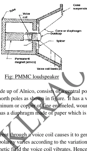
PMMC LOUD SPEAKER:
Principle:
A copper conductor (voice coil) carrying the audio signal moves in and out of the strong magnetic field produced by permanent magnet. This makes the diaphragm to vibrate and produce pressure variations in the air resulting in sound waves.
Fig: PMMC loudspeaker Construction:
It has a permanent magnet made up of Alnico, consists of a central pole that acts as South Pole and the two adjacent poles act as north poles as shown in figure. It has a voice coil, consists of few turns of wire made up of either aluminum or copper of fine enameled, wounded on a Bakelite or mica base to produce high flux. It has a diaphragm made of paper which is molded into a form of cone supported by springs.
Operation:
The flow of electric current through a voice coil causes it to generate magnetic field produced by permanent magnet whose polarity varies according to the variations in the input signal. Due to attraction & repulsion of magnetic field the voice coil vibrates. Hence the diaphragm attached to voice coil also vibrates and causes compression and rarefaction cycles in the air, resulting into sound waves.
Characteristics:
• Sensitivity : 5 to 10%. • Signal to noise ratio : 30 dB.
• Frequency response : 100Hz to 5KHz • Distortion : 5 to 10
• Directivity : Omni- direction • Output impedance : about 1M ohm • Power handling capacity : Few m Watts to 25W. Applications:
• Widely used in radio and TV receivers.
• Used in record players, cassette players and CD players. • Used in low power audio amplifiers.
5. MICROPHONES AND LOUDSPEAKERS
A.A.N.M & V.V.R.S.R POLYTECHNIC GUDLAVALLERU Page 7 BAFFLE:
A baffle is a structure, which can enclose the speaker in order to contain and control the radiation from the rear surface of the speaker. Baffles are made with good sound absorbing materials like plywood, cellotex etc...
NECESSITY OF BAFFLES:
Baffles are used to correct two characteristics of a loud speaker. The first characteristic is
Sound waves produced by front side of diaphragm are out of phase with sound waves produced by back side. If the path difference between these two waves nearer to λ/2 or equal to λ/2 then two waves almost cancel each other. Hence it reduces the output of the loud speaker. The interference of antiphase sound signal can be reduced by using baffles.
Types of Baffles:
Baffles are of 4 types. They are 1) Finite baffle.
2) Infinite baffle. 3) Bass reflex baffle. 4) Acoustic Labyrinth. Finite baffle:
Finite baffle is also known as open baffle. It is in the form of box with back side open. One side of loud speaker is completely shielded from other side if loud speaker is mounted in a closed box.
Infinite Baffle
It is in the form of box with backside closed. In this baffle the loud speaker is completely enclosed by a wooden cabinet, well damped by absorbing material.
5. MICROPHONES AND LOUDSPEAKERS
A.A.N.M & V.V.R.S.R POLYTECHNIC GUDLAVALLERU Page 8
In this baffle, sound waves from rear side of the speaker would not come to front of the speaker. Because in these Baffles the rear side sound waves are completely suppressed. Thus it avoids the interference of antiphase sound waves.
Bass Reflex Baffle
This baffle consists of closed box with two holes. One hole for the speaker. Second hole for the radiations of sound waves produced at the back side of the diaphragm.
These baffles are designed to phase reverse the rare side sound waves. Thus two sound waves are in phase with each other providing additional bass response. Bass reflex produces less distortion than infinite baffles.
Acoustic Labyrinth Baffle:
This is an improved version of bass reflex baffle. For very low audio frequencies, the size of bass reflex is too large. The size of baffle can be reduced by providing partitions with several baffles.
The low frequency waves are allowed to travel additional path difference of λ/2 to get additional phase difference of 180° along with high frequency waves. So that an effective sound output can be obtained.
WOOFERS, SQUAWKERS, TWEETERS:
A single loud speaker cannot give good response to all audio signals. To have uniform response for all audio frequencies, a single speaker may not serve the purpose. Hence a set of speakers called woofers, squawkers and tweeters are used to have uniform response for all audio frequencies.
Woofers:
This type of speaker can respond effectively at very low frequencies in the range up to 1 K Hz. Woofers have a cone of diameter 15.25 cm to 45.75 cm.
5. MICROPHONES AND LOUDSPEAKERS
A.A.N.M & V.V.R.S.R POLYTECHNIC GUDLAVALLERU Page 9 Squawkers:
This type of speaker can respond effectively at medium range frequencies from 1 KHz to 6 KHz. It consists of a small dynamic speaker or horn of 10.15 cm.
Tweeters:
This type of speaker can respond effectively at high frequencies around 7 KHz and above. HORN LOUD SPEAKER:
Principle:
A copper conductor (voice coil) carrying the audio signal moves in and out of the strong magnetic field produced by permanent magnet. This makes the diaphragm to vibrate and produce pressure variations in the air resulting in sound waves.
NEED FOR HORN LOUD SPEAKER:
When large volume of sound is required such as in PA systems, Horn type loud speakers are used. In these loud speaker the sound energy will not radiate directly from the diaphragm. Hence it is an indirect radiating type loudspeaker.
HEAD PHONES:
These are miniature loud speakers enclosed in small housing designated to be worn on head or in ear. These are output devices used to convert electrical signals into sound signals. These headphones provides low intensity and high quality of sound.
TYPES OF HEAD PHONES There are two types of head phones.
1) Electromagnetic head phones. 2) Crystal head phones
1. ELECTROMAGNETIC HEAD PHONES.
Principle: It works on electromagnetic principle that is converting electrical energy in to mechanical energy (sound).
Construction:
It consists of a permanent magnet, voice coil and diaphragm. It has U-shaped magnet connected to two pole pieces N & S used as coils c1 and c2 wounded with insulated copper wire. These coils are connected in series so that the same current passes through each coil. A thin, soft diaphragm made up of iron is placed just above poles with a gap, not more than 0.015 inches.
5. MICROPHONES AND LOUDSPEAKERS
A.A.N.M & V.V.R.S.R POLYTECHNIC GUDLAVALLERU Page 10
Working:
When an AC signal is given to the coils the diaphragm vibrates either reaching near the poles or away from the poles. Due to the vibration in the diaphragm, the air particles also vibrate and therefore sound is produced.
Used:
Telephone exchanges, aero plane equipment, Sound recording equipment, Medical electronic equipment, Communication receivers and Tape recorders.
2) CRYSTAL HEAD PHONES: Principle:
It works on the principle of piezo-electric effect. Piezo - electric effect is the phenomenon that some crystals like (Rochelle salt, lithium sulphate and barium titanate) vibrates when they are subjected to electrical stress.
Construction:
A small crystal slice is arranged in a small plastic container with one side opening as shown in figure. Two terminals are drawn from the crystals to make electrical connection of signal voltage. The opening end of crystal head phone is attached to the ear so that the sound can be heard.
Working:
When the AF signal is applied, it sets the opposite faces of the crystal to vibrate according to amplitude and frequency. Thus it produces mechanical vibrations in the surrounding air medium which are nothing but sound waves.
Applications:
Used in Tape recorders, Stereo amplifier units. Advantages:
• Light in weight.
• Operate with low voltages compare to magnetic headphones. Disadvantages: