University of Mississippi University of Mississippi
eGrove
eGrove
Electronic Theses and Dissertations Graduate School
2016
Reducing Cache Contention On Gpus
Reducing Cache Contention On Gpus
Kyoshin Choo
University of Mississippi
Follow this and additional works at: https://egrove.olemiss.edu/etd
Part of the Computer Sciences Commons
Recommended Citation Recommended Citation
Choo, Kyoshin, "Reducing Cache Contention On Gpus" (2016). Electronic Theses and Dissertations. 454.
https://egrove.olemiss.edu/etd/454
This Dissertation is brought to you for free and open access by the Graduate School at eGrove. It has been accepted for inclusion in Electronic Theses and Dissertations by an authorized administrator of eGrove. For more information, please contact [email protected].
REDUCING CACHE CONTENTION ON GPUS
A Dissertation
presented in partial fulfillment of requirements for the degree of Doctor of Philosophy
in the Department of Computer and Information Science The University of Mississippi
by Kyoshin Choo
Copyright Kyoshin Choo 2016 ALL RIGHTS RESERVED
ABSTRACT
The usage of Graphics Processing Units (GPUs) as an application accelerator has become increasingly popular because, compared to traditional CPUs, they are more cost-effective, their highly parallel nature complements a CPU, and they are more energy efficient. With the popu-larity of GPUs, many GPU-based compute-intensive applications (a.k.a., GPGPUs) present sig-nificant performance improvement over traditional CPU-based implementations. Caches, which significantly improve CPU performance, are introduced to GPUs to further enhance application performance. However, the effect of caches is not significant for many cases in GPUs and even detrimental for some cases. The massive parallelism of the GPU execution model and the resulting memory accesses cause the GPU memory hierarchy to suffer from significant memory resource contention among threads.
One cause of cache contention arises from column-strided memory access patterns that GPU applications commonly generate in many data-intensive applications. When such access patterns are mapped to hardware thread groups, they become memory-divergent instructions whose memory requests are not GPU hardware friendly, resulting in serialized access and performance degradation. Cache contention also arises from cache pollution caused by lines with low reuse. For the cache to be effective, a cached line must be reused before its eviction. Unfortunately, the streaming characteristic of GPGPU workloads and the massively parallel GPU execution model increase the reuse distance, or equivalently reduce reuse frequency of data. In a GPU, the pollution caused by a large reuse distance data is significant. Memory request stall is another contention factor. A stalled Load/Store (LDST) unit does not execute memory requests from any ready warps
in the issue stage. This stall prevents the potential hit chances for the ready warps.
This dissertation proposes three novel architectural modifications to reduce the contention: 1) contention-aware selective caching detects the memory-divergent instructions caused by the column-strided access patterns, calculates the contending cache sets and locality information and then selectively caches; 2) locality-aware selective cachingdynamically calculates the reuse fre-quency with efficient hardware and caches based on the reuse frefre-quency; and 3)memory request scheduling queues the memory requests from a warp issuing stage, frees the LDST unit stall and schedules items from the queue to the LDST unit by multiple probing of the cache. Through sys-tematic experiments and comprehensive comparisons with existing state-of-the-art techniques, this dissertation demonstrates the effectiveness of our aforementioned techniques and the viability of reducing cache contention through architectural support. Finally, this dissertation suggests other promising opportunities for future research on GPU architecture.
ACKNOWLEDGEMENTS
First and foremost, I would like to thank my wife, Jihyun, for fully and pleasantly support-ing me with great patience and believsupport-ing what I am passsupport-ing through after I quit my job. I could not have done any of this long journey without her. Second, I would like to thank my children for their trust, understanding and always being with me to remind of what is most important. My final personal thanks go to my parents and parents-in-laws for praying, always supporting me in every aspect and encouraging me not to give up and to achieve my goal.
Professionally, I would like to thank my advisor Professor Byunghyun Jang for guiding me with the right direction and pushing me to pursue high-quality research, giving me the freedom to explore my own ideas and helping me develop them. His guidance over the last four years has been invaluable and has lead to the goal. Special thanks to David Troendle for being a great colleague. David’s depth of industrial knowledge and insightful thought has helped all the research I have done. I also thank all of the HEROES (HEteROgEneous Systems research) lab members, Tuan Ta, Esraa Abdelmageed, Chelsea Hu, Ajay Sharma, Andrew Henning, Md. Mainul Hassan, Oreva Addoh, Mengshen Zhao, Leo Yi, Michael Ginn, Blake Adams, and Sampath Gowrishetty for their help and invaluable discussion and comments. I would also like to thank Professor Jang’s former colleagues, Dana Schaa and Rafael Ubal for giving insightful comments on the simulator.
I would also list to thank the committee members of my PhD qualifying exam and final PhD dissertation defense: Professor Philip J. Rhodes, Professor Feng Wang and Professor Robert J. Doerksen for their direction and suggested improvements to my dissertation. Last but not least, I would like to thank all the faculty members of Computer and Information Science department
at the University of Mississippi: Professor Dawn E. Wilkins, Professor H. Conrad Cunningham, Professor Yixin Chen, Professor J. Adam Jones, Professor P. Tobin Maginnis, former Professor Jianxia Xue, Ms. Kristin Davidson, and Ms. Cynthia B. Zickos for their academic contribution and friendly support.
TABLE OF CONTENTS
ABSTRACT . . . ii
ACKNOWLEDGEMENTS . . . iv
LIST OF FIGURES . . . x
LIST OF TABLES . . . xii
LIST OF ABBREVIATIONS . . . xiii
INTRODUCTION . . . 1
1.1 Research Challenges . . . 3
1.2 Research Contribution . . . 4
1.3 Organization . . . 5
BACKGROUND. . . 6
2.1 Summary of Terminology Usage . . . 6
2.2 Programming GPUs . . . 7
2.3 Abstract of GPU Architecture . . . 9
2.4 Warp Scheduling . . . 11
2.5 Modern GPU Global Memory Accesses . . . 11
2.5.1 Memory Hierarchy . . . 11
2.5.2 Memory Access Handling . . . 13
2.5.3 Memory Access Characteristics . . . 16
CACHE CONTENTION . . . 19
3.1 Taxonomy of Memory Access Locality . . . 19
3.2 Taxonomy of Cache Contention . . . 24
3.2.1 Cache Miss Contention Classification . . . 25
3.2.2 Cache Resource Contention Classification . . . 26
3.3 Cache Contention Factors . . . 28
3.3.1 Limited Cache Resource . . . 28
3.3.2 Column-Strided Accesses . . . 29
3.3.3 Cache Pollution . . . 30
CONTENTION-AWARE SELECTIVE CACHING . . . 34
4.1 Introduction . . . 34
4.2 Intra-Warp Cache Contention . . . 35
4.2.1 Impact of Memory Access Patterns on Memory Access Coalescing . . . . 35
4.2.2 Coincident Intra-warp Contention Access Pattern . . . 35
4.3 Selective Caching . . . 39
4.3.1 Memory Divergence Detection . . . 39
4.3.2 Cache Index Calculation . . . 41
4.3.3 Locality Degree Calculation . . . 41
4.4 Experiment Methodology . . . 43
4.4.1 Simulation Setup . . . 43
4.4.2 Benchmarks . . . 43
4.5 Experimental Results . . . 44
4.5.1 Performance Improvement . . . 44
4.5.2 Effect of Warp Scheduler . . . 47
4.5.3 Cache Associativity sensitivity . . . 48
4.6 Related Work . . . 48
4.6.1 Cache Bypassing . . . 48
4.6.2 Memory Address Randomization . . . 49
4.7 Summary . . . 50
LOCALITY-AWARE SELECTIVE CACHING . . . 52
5.1 Introduction . . . 52
5.2 Motivation . . . 53
5.2.1 Severe Cache Resource Contention . . . 53
5.2.2 Low Cache Line Reuse . . . 54
5.3 Locality-Aware Selective Caching . . . 55
5.3.1 Reuse Frequency Table Design and Operation . . . 55
5.3.2 Threshold Consideration . . . 58
5.3.3 Algorithm Features . . . 59
5.3.4 Contention-Aware Selective Caching Option . . . 60
5.4 Experiment Methodology . . . 60
5.4.1 Simulation Setup . . . 60
5.4.2 Benchmarks . . . 61
5.5 Experimental Results . . . 62
5.5.1 Performance Improvement . . . 62
5.5.2 Effect of Warp Scheduler . . . 64
5.5.3 Effect of Cache Associativity . . . 65
5.6 Related Work . . . 66
5.6.1 CPU Cache Bypassing . . . 66
5.6.2 GPU Cache Bypassing . . . 66
MEMORY REQUEST SCHEDULING . . . 69
6.1 Introduction . . . 69
6.2 Cache Contention . . . 70
6.2.1 Memory Request Stall due to Cache Resource Contention . . . 70
6.3 Memory Request Scheduling . . . 72
6.3.1 Memory Request Queuing and Scheduling . . . 72
6.3.2 Queue Depth . . . 73
6.3.3 Scheduling Policy . . . 73
6.3.4 Contention-Aware Selective Caching Option . . . 74
6.4 Experiment Methodology . . . 74 6.4.1 Simulation Setup . . . 74 6.4.2 Benchmarks . . . 75 6.5 Experimental Results . . . 76 6.5.1 Design Evaluation . . . 76 6.5.2 Performance Improvement . . . 78
6.5.3 Effect of Warp Scheduler . . . 78
6.5.4 Effect of Cache Associativity . . . 79
6.6 Conclusion . . . 80
RELATED WORK . . . 81
7.1 Cache Bypassing . . . 81
7.1.1 CPU Cache Bypassing . . . 81
7.1.2 GPU Cache Bypassing . . . 82
7.2 Memory Address Randomization . . . 83
7.3 Warp Scheduling . . . 85
7.4 Warp Throttling . . . 86
7.5 Cache Replacement Policy . . . 87
CONCLUSION AND FUTURE WORK . . . 89
8.1 Conclusion . . . 89
8.2 Future Work . . . 90
8.2.1 Locality-Aware Scheduling . . . 90
8.2.2 Locality-Aware Cache Replacement Policy . . . 91
PUBLICATION CONTRIBUTIONS . . . 92
BIBLIOGRAPHY . . . 93
LIST OF FIGURES
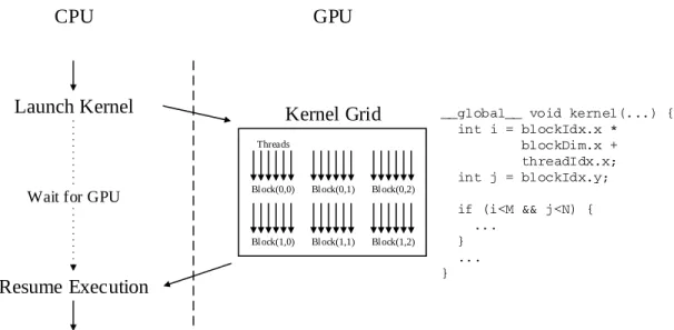
2.1 A GPU kernel execution flow example - A GPU kernel is launched in host CPU, run on GPU, and then returned to the host CPU. An example CUDA code is shown
on the right side. . . 7
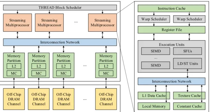
2.2 Baseline GPU architecture. . . 9
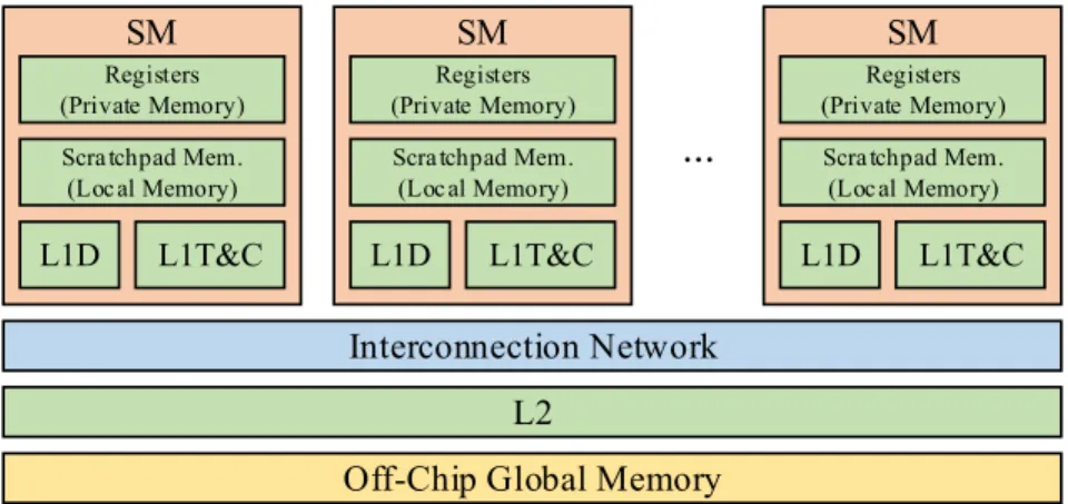
2.3 A typical memory hierarchy in the baseline GPU architecture. L1D, L1T, and L1C stand for L1 data, L1 texture, and L1 constant caches, respectively. . . 12
2.4 A detailed memory hierarchy view. . . 13
2.5 Memory access handling procedure. . . 14
2.6 Coalescing examples of memory-convergent and memory-divergent instructions. . . 15
2.7 GPU memory access characteristics. . . 17
3.1 Memory access pattern for a thread and a warp. . . 22
3.2 Memory access pattern for a thread block. . . 23
3.3 Memory access pattern for an SM. . . 23
3.4 Classification of miss contentions at L1D cache in per kilocycle and in percentage. . 25
3.5 Resource contentions at L1D cache in per kilocycle and in percentage. . . 27
3.6 Classification of cache misses (intra-warp(IW), cross-warp(XW), and cross-block(XB) miss) and comparison with different associativity (4-way and 32-way) caches. Left bar is with 4-way associativity and right with 32-way. . . 29
3.7 Block reuse percentage in the L1D cache. Reuse0represents no-reuse until eviction. 31 3.8 LDST unit is in a stall. A memory request from ready warps cannot progress be-cause the previous request is in stall in the LDST unit. . . 32
3.9 The average number of ready warps when cache resource contention occurs. . . 32
4.1 (Revisited) Coalescing example for convergent instruction and memory-divergent instruction. . . 36
4.2 Example of contending set by column-strided accesses. . . 36
4.3 Example of BICG memory access pattern. . . 37
4.4 The task flow of the proposed selective caching algorithm in an LDST unit. . . 40
4.5 Different selective caching schemes with associativity size n when the memory divergence is detected. . . 42
4.6 Overall improvement - IPC improvement and L1D cache access reduction. . . 46
4.7 IPC improvement for different schedulers. . . 47
4.8 IPC improvement for different associativities. . . 47
5.1 Stall time percentage over simulation cycle time. . . 54
5.2 The number of addresses and instructions for load. . . 56
5.3 Reuse frequency tableentry and operation. . . 57
5.5 IPC improvement with different threshold values for caching decision. . . 59
5.6 Overall improvement: IPC improvement and L1D cache access reduction. . . 63
5.7 IPC improvement with different schedulers. . . 65
5.8 IPC improvement with different associativities. . . 65
6.1 LDST unit in stall and the scheduling queue. . . 70
6.2 The average number of ready warps when cache resource contention occurs. . . 71
6.3 A procedure for the memory request scheduler. . . 72
6.4 A detailed view of the memory request queue and scheduler. . . 73
6.5 IPC improvement with different implementations. . . 77
6.6 Overall IPC improvement. . . 79
6.7 IPC improvement with different schedulers. . . 79
LIST OF TABLES
2.1 GPU hardware and software terminology comparison between standards. . . 6
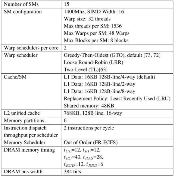
2.2 Baseline GPGPU-Sim configuration. . . 10
3.1 Cache capacity across modern multithreaded processors. . . 28
4.1 Baseline GPGPU-Sim configuration. . . 44
4.2 Benchmarks from PolyBench [31] and Rodinia [14]. . . 45
5.1 Baseline GPGPU-Sim configuration. . . 61
5.2 Benchmarks from PolyBench [31] and Rodinia [14]. . . 62
6.1 Baseline GPGPU-Sim configuration. . . 75
LIST OF ABBREVIATIONS
GPU Graphics Processing Unit
GPGPU General Purpose Graphics Processing Unit SIMT Single-Instruction, Multiple-Thread SIMD Single-Instruction, Multiple-Data MIMD Multiple-Instruction, Multiple-Data APU Accelerated Processing Unit
AMD Advanced Micro Devices IC Integrated Circuit
CPU Central Processing Unit CMP Chip-MultiProcessor
PCI/PCIe Peripheral Component Interconnect / Peripheral Component Interconnect express CUDA Compute Unified Device Architecture
OpenCL Open Computing-Language
API Application Programming Interface DLP Data-Level Parallelism
TLP Thread-Level Parallelism ILP Instruction-Level Parallelism
CU Compute Unit
SM Streaming Multiprocessor PC Program Counter
MACU Memory Access Coalescing Unit MSHR Miss Status Holding Register L1D Level 1 Data
L1I Level 1 Instruction L1T Level 1 Texture L1C Level 1 Constant
L2 Level 2
LLC Last Level Cache MC Memory Controller
FR-FCFS First-Ready First-Come-First-Serve PKI Per Kilo (Thousand) Instructions
MPKI Misses Per Kilo (Thousand) Instructions DRAM Dynamic Random Access Memory GTO Greedy-Then-Oldest
LRR Loose Round Robin
CHAPTER 1
INTRODUCTION
The success of General-Purpose computing on Graphics Processing Unit (GPGPU) tech-nology has made high performance computing affordable and pervasive in platforms ranging from workstations to hand-held devices. Its cost-effectiveness and power efficiency are unprecedented in the history of parallel computing. Following their success in general-purpose computing, GPUs have shown significant performance improvement in many compute-intensive scientific applica-tions, such as geoscience [79], molecular dynamics [4], DNA sequence alignment [84], and large graph processing [47], physical simulations in science [62], and so on. Furthermore, the advent of the big data era has further stimulated the need to leverage the massive computation power of GPUs in accelerating emerging data-intensive applications, such as data warehousing appli-cations [7, 29, 30, 36, 83, 89] and big data processing frameworks [35, 15, 16, 34, 78]. The GPU-based implementations can provide an order of magnitude performance improvement over traditional CPU-based implementations [36, 83].
Since GPUs were originally introduced to efficiently handle computer graphics workloads in specialized applications such as computer-generated imagery and video games, these traditional GPU workloads involved a large amount of data streaming. To deliver high throughput, GPUs rely on massive fine-grained multithreading to hide long latency operations such as global memory accesses [22], which operates by issuing instructions from different threads when the threads being executed are stalled. Given enough threads and enough memory bandwidth, the GPU’s data path can be kept busy, increasing overall throughput at the expense of a single-thread latency.
GPU memory systems have grown to include a multi-level cache hierarchy with both hard-ware and softhard-ware controlled cache structures. For instance, Nvidia Fermi GPUs introduced a relatively large (up to 48 KB per core) and configurable L1 cache and 768 KB L2 cache [64]. Likewise, AMD GCN GPUs also offer a 16 KB L1 cache per core and 768 KB L2 cache [2].
While a throughput processor’s cache hierarchy exploits application inherent locality and increases the overall performance, the massively parallel execution model of GPUs suffers from the resource contention. In particular, for applications whose performances are sensitive to caching efficiency, such cache resource contention degrades the effectiveness of caches in exploiting local-ity, thereby suffering from significant performance drop. Experiments show that caches are not always beneficial to GPU applications [41]. From a suite of 12 Rodinia benchmark [14] applica-tions running on a Nvidia Tesla C2070 GPU with its 16 KB L1 caches turned on and off, only two of them show substantial performance improvements from caching, but two show non-trivial performance degradation. The effect of cache is negligible in other 8 benchmarks [41].
One of the main reasons for the performance degradation is cache contention in the memory hierarchy, especially in the L1 data (L1D) cache. The limited resources that serve the massively parallel memory requests destroy the application’s inherent memory access locality and create se-vere cache contention. Software-based optimization could mitigate this problem, but the effort required to revise the existing code to use cache efficiently is non-trivial [24]. A couple of warp schedulers are also proposed to reduce the contention by limiting the active warps in an SM. How-ever, these approaches reduce the utilization of the GPUs [49, 72, 57].
This dissertation proposes architectural support to reduce the cache contention. In particu-lar, this dissertation identifies the causes of the contention and resolves it by detecting the memory access patterns that significantly destroys the memory access locality, calculating reuse frequency of the memory accesses, and probing cache under memory request stall. This dissertation also demonstrates the effectiveness of these proposed techniques by extensively comparing them with
closely related state-of-the-art techniques.
1.1 Research Challenges
One cause of the cache contention arises fromcolumn-strided memory access patternsthat GPU applications commonly generate in many data-intensive applications. Such access patterns are compiled to warp instructions whose generated memory accesses are not well coalesced. We call these instructionsmemory-divergent instructions. The resulting memory accesses are serially processed in the LDST unit due to the resource contention, stress the L1D caches, and result in serious performance degradation. Even though the impact of memory divergence can be alleviated through various software techniques, architectural support for memory divergence mitigation is still highly desirable because it eases the complexity in the programming and optimization of GPU-accelerated data-intensive applications [72, 73].
Cache contention also arises fromcache pollutioncaused by low reuse frequency data. For the cache to be effective, a cached line must be reused before its eviction. But, the streaming characteristic of GPGPU workloads and the massively parallel GPU execution model increases the reuse distance, or equivalently reduces the reuse frequency of data. If the low reuse frequency data is cached, it can evict the high reuse frequency data in the cache before it is reused. In a GPU, the pollution caused by a low reuse frequency (i.e., large reuse distance) data is significant.
Memory request stall is another contention factor. A stalled LDST unit does not execute memory requests from any ready warps in the previous issue stage. The warp in the LDST unit retries until the cache resource becomes available. During this stall, the private L1D cache is also in a stall, so no other warp requests can probe the cache. However, there may be data in an L1D cache which may become a hit if other ready warps in the issue stage access the cache. The current structure of the issue stage and L1D unit execution do not allow the provisional cache probing in such a case. This stall prevents the potential hit chances for the ready warps.
1.2 Research Contribution
In this dissertation, we have thoroughly investigated three architectural challenges that can severely impact the performance of GPUs and eventually degrade overall performance. For each challenge, this dissertation proposes solutions to reduce the cache contention such as contention-aware selective caching, locality-contention-aware selective caching, and memory request scheduling. We compare the proposed solutions with the closely related state-of-the-art techniques. In particular, this dissertation has made the following contributions.
• Using the application inherent memory access locality classification along with limitation of resources, we classify cache miss contention into 3 categories, intra-warp (IW), cross-warp (XW), and cross-block (XB) contention according to the cause of the misses. We also classify the cache resource contention into 3 categories, LineAlloc fail, MSHR fail, and MissQueue fail.
• We identify and quantify the factors of the contention such as a column-strided pattern and its resulting memory-divergent instruction, cache pollution by low reuse frequency data, and memory request stall.
• We propose a mechanism to detect the column-strided pattern and its resulting memory-divergent instruction which generates memory-divergent memory accesses, calculate the contend-ing cache sets and locality information, and caches selectively. We demonstrate that the contention-aware selective caching can improve the performance more than 2.25x over base-line and reduce memory accesses.
• We propose a mechanism with low hardware complexity to detect the locality of memory requests based on per-PC reuse frequency and cache selectively. We demonstrate that it improves the performance by 1.39x alone and 2.01x along with contention-aware selective
caching over baseline, prevents 73% of the no-reuse data from caching and improves reuse frequency in the cache by 27x.
• We propose a memory request schedule queue that holds ready warps’ memory requests and a scheduler to effectively schedule them to increase the chances of a hit in the cache lines. We demonstrate that there are 12 ready warps on average when the LDST unit is in a stall and this potential improves the overall performance by 1.95x and 2.06x along with contention-aware selective caching over baseline.
1.3 Organization
The rest of this dissertation is organized as follows:
• Chapter 2 details the summary of terminology used in this dissertation, programming model in GPUs, the baseline GPU architecture, and warps scheduling and memory access handling.
• Chapter 3 discusses the data locality, cache miss contention classification, cache resource contention classification and the cache contention factors.
• Chapter 4 presents a contention-aware selective caching proposal to reduce intra-warp asso-ciativity contention caused by memory-divergent instructions.
• Chapter 5 presents a locality-aware selective caching to measure the reuse frequency of the instructions and prevent low reuse data from caching.
• Chapter 6 presents a memory request scheduling to better utilize the cache resource under LDST unit stall.
• Chapter 7 discusses related works.
CHAPTER 2
BACKGROUND
This chapter introduces background knowledge that serves as a foundation for the rest of this dissertation. In particular, Section 2.1 summarizes the terminology usage in all chapters throughout this dissertation. Section 2.2 describes the GPU programming flow and work-item formation from the software point of view. Section 2.3 presents the abstract model of GPU archi-tecture used in this dissertation. Section 2.4 and Section 2.5 explain how the warps are assigned to the execution units and how global memory requests are handled in the GPU memory hierarchy. More detailed background knowledge can be found in many other references [3, 66, 37, 52].
2.1 Summary of Terminology Usage
This Dissertation CUDA [66] OpenCL [52]
thread thread work-item
warp warp wavefront
thread block thread block work-group
SIMD lane CUDA core processing element
Streaming Multiprocessor (SM) SM Compute Unit (CU) private memory local memory private memory
local memory shared memory local memory global memory global memory global memory
Table 2.1. GPU hardware and software terminology comparison between standards.
Table 2.1 summarizes the terminology used in this dissertation. We present this summary to avoid confusion between multiple equivalent technical terms from multiple competing GPGPU
CPU GPU
Launch Kernel
Resume Execution
Wait for GPU Bl ock(0,0) Bl ock(0,1) Bl ock(0,2)
Bl ock(1,0) Bl ock(1,1) Bl ock(1,2) Threads
Kernel Grid __global__ void kernel(...) { int i = blockIdx.x * blockDim.x + threadIdx.x; int j = blockIdx.y; if (i<M && j<N) { ... } ... }
Figure 2.1. A GPU kernel execution flow example - A GPU kernel is launched in host CPU, run on GPU, and then returned to the host CPU. An example CUDA code is shown on the right side.
programming frameworks and industry standards. Detailed definitions of the terms are presented in the following sections. A more thorough explanation of GPU terminologies other than the explanations introduced here can be found in various programming guides and framework specifi-cations [51, 52, 66].
2.2 Programming GPUs
Programming environments and abstractions have been introduced to help software devel-opers write GPU applications. Nvidia’s CUDA [66] and Khronos Group’s OpenCL [51, 52] are popular frameworks. Despite the terminology differences summarized in Table 2.1, these frame-works have very similar programming models, as introduced below.
Depending on the system configuration, a GPU can be connected via a PCI/PCIe bus or reside on the same die with the CPU. Applications programmed in high-level programming lan-guages, such as CUDA [66] and OpenCL [51, 52], begin execution on CPUs. The GPU portion of the code is launched from the CPU code in the form ofkernels. Depending on the system, data to be used by a GPU are transferred through the PCI/PCIe bus through an internal interconnection
between the CPU and GPU, or through pointer exchange.
A CUDA or OpenCL program running on a host CPU contains one or more kernel func-tions. These kernels are invoked by the host program, offloaded to a GPU device, and executed there. The kernel code specifies operations to be performed by the GPU from the perspective of a single GPU thread. At kernel launch, the host specifies the total number of threads executing the kernel and their thread grouping. As shown in Figure 2.1, a kernel divides its work into a grid of identically sizedthread blocks. The size of a thread block is the number of threads (e.g., 256) in that block. From the programmer’s perspective, every instruction in the kernel is concurrently executed by all threads in the same thread block. However, there is a limited number of hardware lanes (e.g., 32) that an SM can execute concurrently on real hardware. Consequently, threads are executed in groups of hardware threads calledwarps. The number of threads in a warp is called the size of the warp.
GPU threads have access to various memory spaces. A thread can access its ownprivate memory, which is not accessible by other threads. Threads in the same block can share data and synchronize via local memory, and all threads in a kernel can access global memory. The local and global memories support atomic operations. Global memory is cached in on-chip private L1 data (L1D) cache and shared L2 cache. Much of this dissertation focuses on reducing contention on this L1D cache.
Finally, because every thread executes the same binary instructions as other threads in the same kernel, it must use its thread ID and thread block ID variables to determine its own identity and operate on its own data accordingly. Those IDs can be one- or multi-dimensional, and they are represented by consecutive integer values in each dimension of the block starting with the first dimension, as shown in Figure 2.1.
Texture Cache Execution Units Streaming Multiprocessor Streaming Multiprocessor Streaming Multiprocessor ... Interconnection Network Memory Partition L2 MC Memory Partition L2 MC Memory Partition L2 MC Memory Partition L2 MC ... Off-Chip DRAM Channel Off-Chip DRAM Channel Off-Chip DRAM Channel Off-Chip DRAM Channel ...
THREAD Block Scheduler Instruction Cache
Warp Scheduler Warp Scheduler Register File SIMD SIMD ... SFUs LD/ST Units Interconnection Network L1 Data Cache Constant Cache Local Memory
Figure 2.2. Baseline GPU architecture.
2.3 Abstract of GPU Architecture
The modern GPU architecture is illustrated in Figure 2.2. A GPU consists of a thread block scheduler, an array ofStreaming Multiprocessors (SMs), an interconnection network between SMs and memory modules, and global memory units. Off-chip DRAM memory (global memory) is connected to the GPU through a memory bus. Each SM is a highly multi-threaded and pipelined SIMD processor. SIMD lanesexecute distinct threads, operate on a large register file, and progress in lock-step with other threads in the SIMD thread group (warp).
The SM architecture is detailed in the right side of Figure 2.2. It consists of warp sched-ulers, a register file, SIMD lanes, Load/Store(LDST) units, various on-chip memories including L1D cache, local memory, texture cache, and constant cache. LDST units manage accesses to various memory spaces. Depending on the data being requested, GPU memory requests are sent to either L1D cache, local memory, texture cache or constant cache. Each memory partition consists of L2 cache and a memory controller (MC) that controls off-chip memory modules. An
intercon-Number of SMs 15
SM configuration 1400Mhz, SIMD Width: 16 Warp size: 32 threads Max threads per SM: 1536 Max Warps per SM: 48 Warps Max Blocks per SM: 8 blocks Warp schedulers per core 2
Warp scheduler Greedy-Then-Oldest (GTO), default [73, 72] Loose Round-Robin (LRR)
Two-Level (TL)[63]
Cache/SM L1 Data: 16KB 128B-line/4-way (default) L1 Data: 16KB 128B-line/2-way
L1 Data: 16KB 128B-line/8-way
Replacement Policy: Least Recently Used (LRU) Shared memory: 48KB
L2 unified cache 768KB, 128B line, 16-way Memory partitions 6
Instruction dispatch 2 instructions per cycle throughput per scheduler
Memory Scheduler Out of Order (FR-FCFS) DRAM memory timing tCL=12,tRP=12,
tRC=40,tRAS=28, tRCD=12,tRRD=6
DRAM bus width 384 bits
Table 2.2. Baseline GPGPU-Sim configuration.
nection network handles data transfer between the SMs and L2 caches, and the memory controller handles data transfer between L2 and off-chip memory modules.
We use GPGPU-Sim [5] for detailed architectural simulation of the GPU architecture. The details of the architectural specification can be found in the GPGPU-Sim 3.x manual [82]. We present the details of our simulation setup and configurations in Table 2.2.
2.4 Warp Scheduling
As shown in Figure 2.2, each SM contains multiple physical warp lanes (SIMD) and two warp schedulers, independently managing warps with even and odd warp identifiers. In each cycle, both warp schedulers pick one ready warp and issue its instruction into the SIMD pipeline back-end [64, 65]. To determine the readiness of each decoded instruction, a ready bit is used to track its dependency on other instructions. It is updated in the scoreboard by comparing its source and destination registers with other in-flight instructions of the warp. Instructions are ready for scheduling when their ready bits are set (i.e., data dependencies are cleared).
GPU scheduling logic consists of two stages: qualification and prioritization. In the qualifi-cation stage, ready warps are selected based on the ready bit that is associated with each instruction. In the prioritization stage, ready warps are prioritized for execution based on a chosen metric, such as cycle-based round-robin [63, 44], warp age [73, 72], instruction age [12], or other statistics that can maximize resource utilization or minimize stalls in memory hierarchy or in execution units. For example, the Greedy-Then-Oldest (GTO) scheduler [73, 72] maintains the highest priority for the currently prioritized warp until it is stalled. The scheduler then selects the oldest among ready warps for scheduling. GTO is a commonly used scheduler because of its good performance in a large variety of general purpose GPU benchmarks.
2.5 Modern GPU Global Memory Accesses 2.5.1 Memory Hierarchy
An SM contains physical memory units shared by all its concurrently executing threads. Private memory mapped to registers is primarily used for threads to store their individual states and contexts. Local memory mapped to programmer-managed scratch-pad memories [8] is used to share data within a thread block. All cores share a large, off-chip DRAM to which global memory maps. Modern GPUs also have a two-level cache hierarchy (L1D and L2) for global memory
...
Interconnection Network L2
Off-Chip Global Memory SM
Scra tchpad Mem. (Loc al Memory)
Registers (Private Memory)
L1D L1T&C
SM
Scra tchpad Mem. (Loc al Memory)
Registers (Private Memory)
L1D L1T&C
SM
Scra tchpad Mem. (Loc al Memory)
Registers (Private Memory)
L1D L1T&C
Figure 2.3. A typical memory hierarchy in the baseline GPU architecture. L1D, L1T, and L1C stand for L1 data, L1 texture, and L1 constant caches, respectively.
accesses. Texture and constant caches (L1T and L1C) have existed since the early graphics-only GPUs [33]. Figure 2.3 shows the described memory hierarchy in the baseline GPU architecture.
Current Nvidia GPUs have configurable L1D caches whose size can be 16, 32, or 48 KB. The L1D cache in each core shares the same total 64 KB of memory cells with local memory, giving users dynamically configurable choices regarding how much storage to devote to the L1D cache versus the local memory. AMD GPU L1D caches have a fixed size of 16 KB. Current Nvidia GPUs have non-configurable 768 KB - 1.5 MB L2 caches, while AMD GPUs have 768 KB L2 caches. L1T and L1C are physically separate from L1D and L2, and they are only accessed through special constant and texture instructions. GPU programmers are usually encouraged to declare and use local memory variables as much as possible because the on-chip local memories have a much shorter latency and much higher bandwidth than the off-chip global memory. Small, but repeatedly used data are good candidates to be declared as local memory objects. However, because local memories have a limited capacity and a GPU core cannot access another core’s local memory, many programs cannot use local memories due to their data access patterns. In these situations, the global memory with its supporting cache hierarchy should be the choice.
Threads from the same thread block must execute on the same SM in order to use the SM’s scratch-pad memory as a local memory. However, when thread blocks are small, multiple thread
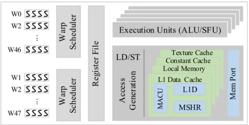
LD/ST Constant CacheTexture Cache Local Memory W a rp S c h e d u le r R e g ist e r F il e
Execution Units (ALU/SFU)
W a rp S c h e d u le r .. . W0 W46 W2 W1 W47 W2 A c ce s s G e n e ra ti o n L1 Data Cache M AC U L1D MSHR M em P ort .. .
Figure 2.4. A detailed memory hierarchy view.
blocks may execute on a single SM as long as core resources are sufficient. Specifically, four hardware resources - the number of thread slots, the number of thread block slots, the number of registers, and the local memory size - dictate the number of thread blocks that can execute concurrently on a SM; we call this number a SM’s (thread) block concurrency. An interconnection network connects SMs to the DRAM via a distributed set of L2 caches and memory modules. A certain number of memory modules share one memory controller (MC) that sits in front of them and schedules memory requests. This number varies from one system to the other. The DRAM scheduler queue size in each memory module impacts the capacity to hold outstanding memory requests.
2.5.2 Memory Access Handling
Figure 2.4 shows a typical thread processing and memory hierarchy on an SM. An instruc-tion is fetched and decoded for a group of threads called awarp. The size of warp can vary across devices, but is typically 32 or 64. All threads in a warp execute in an SIMD fashion with each thread using its unique thread ID to map to its data. A user-defined thread block is composed of multiple warps. At issue stage, a warp scheduler selects one of the ready warps for execution.
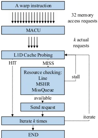
Figure 2.5 shows the detailed global memory access handling. A memory instruction is issued on a per warp-basis with usually 32 threads in Nvidia Fermi, or 64 threads in AMD Southern
A warp instruction 32 memory access requests MACU kactual requests L1D Cache Probing HIT Resource checking: Line MSHR MissQueue stall Send request available iterate Iteratektimes END MISS
Figure 2.5. Memory access handling procedure.
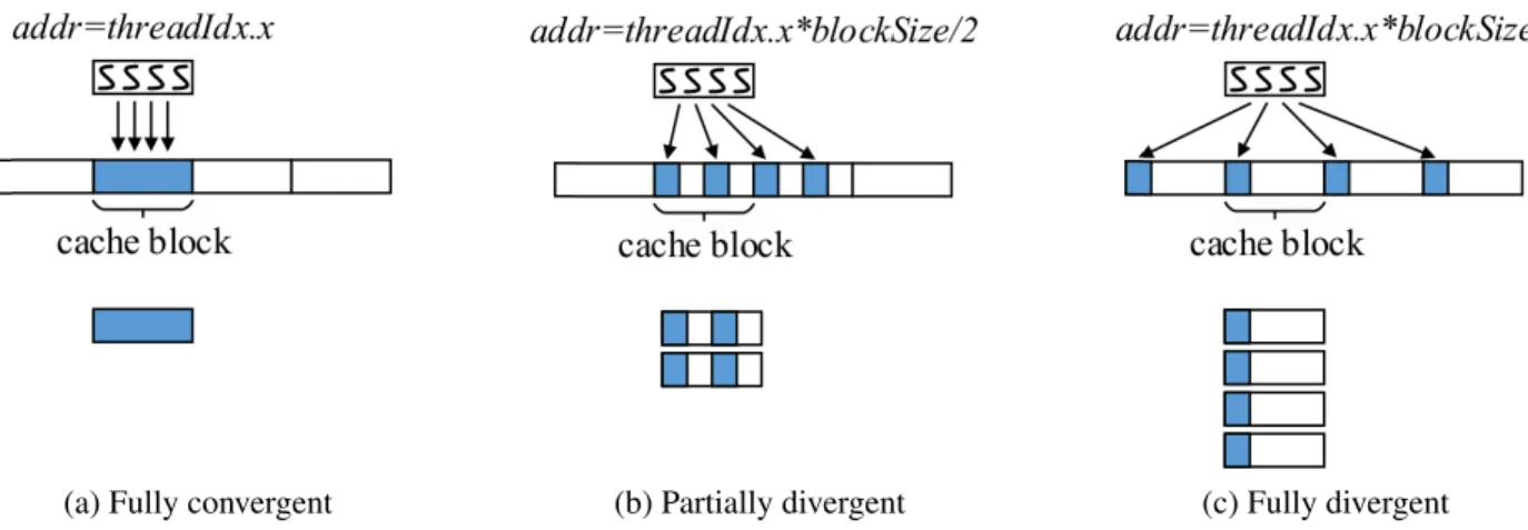
Island architectures. Once a memory instruction for global memory is issued, it is sent to a Memory Access Coalescing Unit (MACU) for memory request generation to the next lower layer of the memory hierarchy. To minimize off-chip memory traffic, the MACU merges simultaneous per-thread memory accesses to the same cache line. Depending on the stride of the memory addresses among threads, the number of resulting memory requests varies. For example, when 4 threads in a warp access 4 consecutive words, i.e., stride-1 access, in a cache line-aligned data block, the MACU will generate only one memory access to L1D cache as shown in Figure 2.6a. Otherwise, simultaneous multiple accesses are coalesced to a smaller number of memory accesses to L1D cache to fetch all required data. In the worst case, the 4 memory accesses are not coalesced at all and generate 4 distinct memory accesses to L1D cache as shown in Figure 2.6c. Therefore, a fully memory-divergent instruction can generate as many accesses as the warp size. Theworking set is defined as the amount of memory that a process requires in a given time interval [20]. When
(a) Fully convergent
add
(b) Partially divergent
ad
(c) Fully divergent
Figure 2.6. Coalescing examples of memory-convergent and memory-divergent instructions.
many memory-divergent instructions are issuing memory requests, the working set size becomes large. If it exceeds the cache size, it causes cache contention. In the rest of this dissertation, the memory instructions that generate only one memory access after MACU are called memory-convergent instructions, and the others are called memory-divergent instructions. The resultant memory accesses from an MACU are sequentially sent to L1D via a single 128-byte port [12].
When a load memory request hits in L1D, the requested data is written back to the register file and dismissed. If it misses in L1D, the request checks if it can allocate enough resources to process the request. When the request acquires resources, it is sent to the next lower memory hierarchy to fetch data. Otherwise, it retries at next cycle to acquire the resources. The resources to be checked by the request are a line in a cache set, a Miss Status Holding Register (MSHR) entry and a miss queue entry. An allocate-on-miss policy cache allocates one cache line in the destination set of cache if available. Otherwise, it fails allocation on the cache and retries at the next cycle until the resource is ready. An allocate-on-fill policy cache skips this process and attempts allocation on reception of the requested data from the lower memory hierarchy. The MSHR is used to track in-flight memory requests and merge duplicate requests to the same cache line. Upon MSHR allocation, a memory request is buffered into the memory port for network transfer. An MSHR entry is released after its corresponding memory request is back and all accesses to that block are
serviced. Memory requests buffered in the memory port are drained by the on-chip network in each cycle when lower memory hierarchy is not saturated.
Since L1D caches are not coherent across cores, every global memory store is treated as a write-through transaction followed by invalidation on the copies in the L1D cache [2]. Store instructions require no L1D cache resources and are directly buffered into the memory port to the L1 cache. For this reason, only global memory loads, not stores, are taken into consideration in this dissertation.
2.5.3 Memory Access Characteristics
Since GPUs have a different programming model and execution behavior from traditional CPUs, their memory access also has unique characteristics different from traditional processors. According to our evaluation and analysis of cache behavior and performance [19], GPU memory access has the following characteristics.
Considerably low cache hit rate in L1D: As shown in Figure 2.7a, L1D cache hit rate on GPUs is considerably lower than those on the CPUs (49% vs. 88% on average). This suggests the reuse rate of the data in the cache is not high. This low cache hit rate in L1D results in increased memory traffic to the lower levels of the memory hierarchy, L2 and off-chip global memory. It leads to overall longer memory latency, and thus degrades the overall memory performance.
Compulsory misses dominate: The main cause of the low cache hit rate for L1D results from the fact that compulsory misses dominate in an L1D cache. Compulsory miss is sometimes referred as cold miss or first reference miss since this miss occurs when the data block is brought to the cache for the first time. From Figure 2.7b, the compulsory miss rate over total misses are about 65% on average. This behavior contradicts the conventional wisdom that compulsory misses are negligibly small on traditional multi-core processors [74]. This difference shows that the data in GPU is not reused much, that is, data reusability is very low. This is different from the CPU
BS DCT RG FW FWT MT SLA RED RS HIST BLS BO AVG 0 0.2 0.4 0.6 0.8 1
Cache Hit Rate
CPU GPU
(a) Cache hit rate on L1D cache.
BS DCT RG FW FWT MT SLA RED RS HIST BLS BO AVG
0 50 100
Percentage (%)
(b) Compulsory miss rate in L1D cache.
BS DCT RG FW FWT MT SLA RED RS HIST BLS BO AVG
0 8 16 24 32 Coalescing Degree
(c) Coalescing degree in Memory Access Coalescing Unit (MACU).
Figure 2.7. GPU memory access characteristics.
memory access patterns where temporal and spatial localities are used for caching. Tian et al. [80] show that zero-reuse blocks in the L1 data cache are about 45% on average GPU applications.
Coalescing occurs massively: As described in Section 2.2, GPUs achieve high performance through massively parallel thread execution. Such massive thread execution subsequently issues many memory requests to its private L1D cache. Since typical memory accesses are known to be regular with strided patterns in GPUs, massive coalescing occurs at the MACU. Figure 2.7c shows the coalescing degree for each benchmark. Thecoalescing degreeis defined as the ratio of the number of memory requests generated by warp instructions to the total L1D cache requests. Since the warp size is 32, maximum coalesce degree is 32. As can be seen in Figure 2.7c, on some
benchmarks such as bs, dct, and bo, the coalescing degree is very high, more than 16. On average, approximately 7 memory requests are coalesced to the same cache line. In other words, the memory traffic reduction by the MACU is 7 to 1.
CHAPTER 3
CACHE CONTENTION
This chapter introduces the taxonomy of memory access locality that GPU applications inherently have. This chapter also introduces two other cache contention classifications, miss con-tention and resource concon-tention, followed by the factors that are involved in the cache concon-tention. As noted in Section 2.5.2, only global memory loads - not stores - are taken into consideration, since global memory stores bypass the L1D cache and do not affect the cache contention described in this dissertation.
3.1 Taxonomy of Memory Access Locality
A comprehensive understanding of GPU memory access characteristics, especially locality, is essential to a better understanding of contention in the memory hierarchy of a GPU. We introduce the four-category memory access locality including intra-thread locality, intra-warp locality, cross-warp locality, and cross-block locality. The definition of each category follows.
• Intra-thread data locality (IT)applies to memory instructions being executed by one thread in a warp. This category captures the temporal and spatial locality of a thread which has a similar pattern to that of the CPU workload.
• Intra-warp data locality (IW)applies to memory instructions being executed by threads from the same warp. Depending on the result of coalescing, the instructions are classified to either memory-convergent (in which thread accesses are mapped to the same cache block) or memory-divergent (in which thread accesses are mapped to more than 2 cache blocks).
When the instruction is memory-convergent, the spatial locality between threads is taken care of by the coalescer (MACU), and therefore, the number of memory requests per instruction becomes one, which is the same as the IT locality case. When the instructions are not memory-convergent, each instruction generates multiple memory requests and the working set size becomes larger.
• Cross-warp Intra-block data locality (XW) applies to memory instructions being executed by threads from the same thread block, but from different warps in the thread block. If these threads access data mapped to the same cache line, they have XW locality. Warp scheduler and memory latency affect the locality.
• Cross-warp Cross-block data locality (XB) applies to memory instructions being executed by threads from different thread blocks, but in the same SMs. If these threads access data mapped to the same cache line, they have XB locality. The thread block scheduler, warp scheduler and memory latency affect the locality. XB locality between thread blocks mapped to different SMs is not considered since they do not show locality in an SM.
Since more threads are involved in the memory access locality for GPUs as described in the taxonomy above, we need to review the definition of temporal and spatial locality. The traditional definition of temporal locality and spatial locality are the followings [37].
Temporal locality: If a particular memory location is referenced at a particular time, then it is likely that the same location will be referenced again in the near future. There is a temporal proximity between the adjacent references to the same memory location. In this case, it is common to make an effort to store a copy of the referenced data in special memory storage, which can be accessed faster. Temporal locality is a special case of spatial locality, namely when the prospective location is identical to the present location.
Listing 3.1. SYRK benchmark kernel
1
__global__ void syrk_kernel(...)
2
{
3 /* C := alpha*A*A’ + beta*C , NxN matrix*/
4
int j = blockIdx.x * blockDim.x + threadIdx.x;
5
int i = blockIdx.y * blockDim.y + threadIdx.y;
6
7
if ((i<N) && (j<N)) {
8
c[i*N+j] = c[i*N+j] * beta;
9
1
10
for(int k=0; k<N; k++) {
11
c[i*N+j] = alpha * a[i*N+k] * a[j*N+k] + c[i*N+j];
12 2 3 4 13 } 14 } 15 }
it is likely that nearby memory locations will be referenced in the near future. In this case, it is common to attempt to guess the size and shape of the area around the current reference for which it is worthwhile to prepare faster access.
To visualize the above category in detail, we choose a benchmark, syrk, in Polybench/ GPU [31]. Thesyrk benchmark has intra-warp (IW) locality as well as cross-warp intra-block (XW) and cross-warp cross-block (XB) locality. The example kernel code in Listing 3.1 and address distribution per category are given. For simplicity in this example, we assumeN = 16, warp size 4, thread block size 16. There are 16 thread blocks total, and the maximum warps in an SM are 4 thread blocks.
The code listing above shows four load instructions, which are highlighted and labeled in circled numbers in the listing. The load instruction execution sequence is {1,{2,3,4}N} where {...}N represents repetition of the sequence in the curly bracket and the N value is 16 in this
case. SinceN is 16, there are 49 load memory accesses per thread. The memory address pattern for the thread 0 (T0) is shown in Figure 3.1a, intra-thread locality (IT). Since load instructions 1 and 4 read the same memory address regardless of the k value, these load instructions have temporal locality in a thread memory access. On the other hand, since load instructions 2 and 3
Access Cycle 0 5 10 15 20 25 30 35 40 45 50 Memory Address 0 100 200
300 Memory Access Pattern for a thread (T0)
T0
Temporal locality
Spatial locality
(a) Memory access pattern for a thread (T0) - Intra-thread (IT) locality.
Access Cycle 0 5 10 15 20 25 30 35 40 45 50 Memory Address 0 100 200
300 Memory Access Pattern for a warp (W0)
T0 T1 T2 T3 Coalescing Direction
(b) Memory access pattern for a warp (W0withT0, T1, T2, T3) - Intra-warp (IW) locality. Memory accesses within a rectangle can be coalesced.
Figure 3.1. Memory access pattern for a thread and a warp.
are accessing neighboring memory addresses, respectively, this shows spatial locality. Hence, the memory pattern for the thread T0 shows both temporal and spatial locality.
The next scope is intra-warp locality (IW). Figure 3.1b shows the memory address pattern for the 4 threads, T0, T1, T2, and T3, in the same warp. Since coalescing occurs at the intra-warp level, as marked with red rectangles in the figure, coalescing occurs within the red rectangle, in the vertical direction of address distribution in a cycle. As explained in Section 2.5.2, only memory addresses within the cache block size are coalesced. Therefore, when the memory requests are scattered enough not to be grouped into a cache line, i.e., N is larger, the memory-divergent instruction generates up to warp-size memory requests. The temporal locality and spatial locality observed in the IT locality graph still hold.
The next scope is cross-warp intra-block (XW) locality as in Figure 3.2. From this scope and beyond, the warp scheduler plays a very important role. The address pattern without the warp scheduler effect is shown in Figure 3.2a. The pairs,{W0,W2}, and{W1,W3}show very similar
Access Cycle 0 5 10 15 20 25 30 35 40 45 50 Memory Address 0 100 200 300
400 Memory Access Pattern for a thread block (TB0)
W0 W1 W2 W3
(a) Memory access pattern for a thread block (T B0) - ideal - Cross-warp Intra-block (XW) locality.
Access Cycle 0 10 20 30 40 50 60 70 Memory Address 0 100 200 300
400 Memory Access Pattern for a thread block (TB0)
W0 W1 W2 W3
(b) Memory access pattern for a thread block - skewed by warp scheduler effect - Cross-warp Intra-block (XW) locality.
Figure 3.2. Memory access pattern for a thread block.
Access Cycle 0 5 10 15 20 25 30 35 40 45 50 Memory Address 0 100 200 300
400 Memory Access Pattern for all thread blocks
TB0 TB1 TB2 TB3
(a) Memory access pattern for an SM - ideal - Cross-warp Cross-block (XB) locality.
Access Cycle 0 10 20 30 40 50 60 70 80 Memory Address 0 100 200 300
400 Memory Access Pattern for all thread blocks
TB0 TB1 TB2 TB3
(b) Memory access pattern for an SM - skewed by warp scheduler effect - Cross-warp Cross-block (XB) locality.
memory access pattern and that pattern has very good spatial and temporal locality. When we include the warp scheduler effect as shown in Figure 3.2b, the memory accesses are more scattered in time. In this figure, by scheduling the locality pairs apart, for example {W0, W1} first and
{W2, W3}later, the locality shown in the code can be completely destroyed. As shown, the x-axis of Figure 3.2b is also extended to 1.5x cycles longer. When it comes to the real warp scheduler introduced in Section 2.4, the memory access pattern is much more complex. As the number of memory requests grows, the chances of thrashing grow high since, in a short period of time, many memory accesses are contending to acquire the cache resources.
The largest scope is cross-warp cross-block (XB) locality. Figure 3.3 shows this case. The working set of memory access grows even larger than in the XW case. Figure 3.3a shows the memory access pattern without the effect of the warp scheduler and the memory latency. This still shows good inter-block locality between the blocks without scheduler effect, while the scheduler effect affects the locality pattern significantly.
In summary, GPU applications have inherent memory access locality either at the thread level, warp level, cross-warp level or cross-block level. Since threads are executed as a warp in GPUs, the thread level locality is absorbed to the warp level by coalescing at the MACU unit. However, when the memory accesses with locality are executed in a GPU, they are competing with each other to acquire the limited resources such as warp schedulers, LDST units, caches, and other resources in the GPU. When the number of memory accesses at a certain time interval (working set) is large, the contention becomes severe. This contention creates a serious performance bottleneck.
3.2 Taxonomy of Cache Contention
Due to the resource limitations of the memory hierarchy, as introduced in Section 3.1, the inherent memory access locality can be dramatically reduced and causing cache miss contention and cache resource contention. According to the cause of the contentions, we classify them as
2dconv 2mm 3dconv 3mm atax bicg gesummv mvt syr2k syrk backprop bfs hotspot lud nw srad1 srad2 mean 0 500 1000 Per kilocycle Intra-warp contention Cross-warp contention Cross-block contention
(a) Miss contention classification (per kilocycle).
2dconv 2mm 3dconv 3mm atax bicg gesummv mvt syr2k syrk backprop bfs hotspot lud nw srad1 srad2 mean 0 50 100 Percentage (%)
(b) Miss contention classification (percentage).
Figure 3.4. Classification of miss contentions at L1D cache in per kilocycle and in percentage.
follows.
3.2.1 Cache Miss Contention Classification
When a cache miss occurs, the new memory request must evict a previously residing cache line (victim cache line). Depending on the warp ID and block ID relationship between the in-serting and evicting lines, the cache miss is classified into intra-warp, cross-warp, and cross-block contention. We classify the GPU cache miss contention as follows:
• Intra-Warp contention (IW)refers to contention among memory requests from threads in the same warp. The contention can occur among the memory requests from the same instruction of the same warp or among the memory requests from different instructions of the same warp. We define the former case as coincident IW contention because the contention is
between the requests occurring at the same time frame (during coalescing), and the latter case asnon-coincident IWcontention.
• Cross-Warp Contention (XW)refers to contention among memory requests from threads in different warps. Since many warps execute concurrently in an SM, the memory working set size from those warps tends to be large. Hence, the cross-warp contention frequently causes capacity misses. Data blocks are evicted frequently before any reuse occurs, especially when the reuse distance is long. More importantly, memory requests with no reuse may evict cache lines that have high reuse, resulting in cache pollution.
• Cross-Block Contention (XB)refers to contention among memory requests from threads in different thread blocks. This is a subset of the XW contention where contention source is from two different blocks.
Figure 3.4 shows the miss contention classification in L1D cache depending on the cause of miss contention. From the figure, about 45% of the cache misses on average are from intra-warp contention. Especially, for the benchmarks such asatax, bicg, gesummv, mvt, syr2k, andsyrk, intra-warp contention dominates the miss contention.
3.2.2 Cache Resource Contention Classification
When an incoming memory access request is serviced in the cache hierarchy after a miss, it checks the cache to see if there are enough resources such as cache line, MSHR entry, and miss queue entry to serve the request. When the cache does not have enough resources, the incoming request is stalled and retries until it acquires the cache resources it needs. Depending on the type of the resource acquisition fail, we classify the resource contention into three categories:
• Line Allocation Fail occurs when there is no cache line available for allocation. When a request misses in a cache, the request tries to find an available line in the cache for allocation
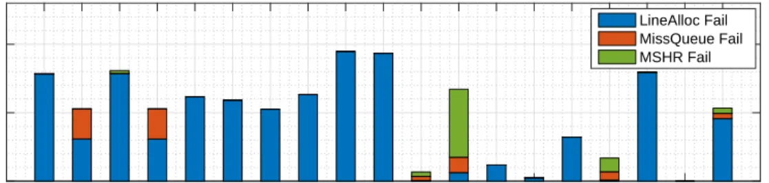
2dconv 2mm 3dconv 3mm atax bicg gesummv mvt syr2k syrk backprop bfs hotspot lud nw srad1 srad2 mean 0 500 1000 Per kilocycle LineAlloc Fail MissQueue Fail MSHR Fail
(a) Resource contention (per kilocycle).
2dconv 2mm 3dconv 3mm atax bicg gesummv mvt syr2k syrk backprop bfs hotspot lud nw srad1 srad2 mean 0 50 100 Percentage (%)
(b) Resource contention (percentage).
Figure 3.5. Resource contentions at L1D cache in per kilocycle and in percentage.
underAllocation-on-Misspolicy. When all the lines are reserved, line allocation fail occurs and the request retries until a line is available.
• MSHR Failoccurs when the request can reserve a line in a set but there is no entry available in the MSHR. The MSHR holds an active request sent to the lower level cache until the request returns with data.
• Miss Queue Failoccurs when a line is available to be allocated and there is a MSHR entry available, but the miss queue to the lower level is full. It also means that the lower level cache is blocked.
The graph in Figure 3.5 shows the metrics for each type of resource reservation fails. Ap-proximately 80% of the resource contention is LineAllocFail and the resource contention takes
Type Processor L1 cache Threads Cache / Core / Thread CPU Intel Haswell 32 KB 2 16 KB Intel Xeon-Phi 32 KB 4 8 KB AMD Kaveri 64 KB 2 32 KB
Type Processor L1 cache Threads Cache Cache / Core / Thread / Warp
GPU
Nvidia Fermi 48 KB 1536 32 B 1 KB
Nvidia Kepler 48 KB 2048 24 B 750 B
AMD SI 16 KB 2560 6.4 B 410 B
Table 3.1. Cache capacity across modern multithreaded processors.
about 500 cycles per kilocycles on average for the benchmarks we tested.
3.3 Cache Contention Factors 3.3.1 Limited Cache Resource
Modern GPUs have widely adopted hardware-managed cache hierarchies inspired by the successful deployment in CPUs. However, traditional cache management strategies are mostly designed for CPUs and sequential programs; replicating them directly on GPUs may not deliver the expected performance as GPUs’ relatively smaller cache can be easily congested by thousands of threads, causing serious contention and thrashing.
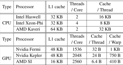
Table 3.1 lists the L1D cache capacity, thread volume, and per-thread and per-warp L1 cache size for several state-of-the-art multithreaded processors. For example, the Intel Haswell CPU has 16 KB cache per thread per core available, but, the NVIDIA Fermi GPU has only 32 B cache per thread available, which is significantly smaller than CPU cache. Even if we consider the cache capacity per warp (i.e., execution unit in a GPU), it has only 1 KB per warp, which is still far smaller than for the CPU cache. Generally, the per-thread or per-warp cache share for GPUs is much smaller than for CPUs. This suggests the useful data fetched by one warp is very likely
2dconv 2mm 3dconv 3mm atax bicg gesummv mvt syr2k syrk backprop bfs hotspot lud nw srad1 srad2 mean 0 50 100 Percentage IW XW XB Left 4 Right 32
Figure 3.6. Classification of cache misses (intra-warp(IW), cross-warp(XW), and cross-block(XB) miss) and comparison with different associativity (4-way and 32-way) caches. Left bar is with 4-way associativity and right with 32-way.
to be evicted by other warps before actual reuse. Likewise, the useful data fetched by a thread can also be evicted by other threads in the same warp. Such eviction and thrashing conditions destroy locality and impair performance. Moreover, the excessive incoming memory requests can lead to significant delay when threads are queuing for the limited resources in caches (e.g., a certain cache set, MSHR entries, miss buffers, etc.). This is especially so during an accessing burst period (e.g., in the starting phase of a kernel) or set-contending coincident IW contention.
3.3.2 Column-Strided Accesses
The cache contention analysis in Section 3.2 shows that the intra-warp contention takes about 45% of the overall cache miss contention and that 80% of the resource contention is line allocation fail. The analysis infers that the intra-warp associativity contention has a big impact on GPU performance. In order to illustrate the problem of intra-warp contention and quantify their direct impacts on GPU performance, we used two L1D configurations that have the same total capacity (16 KB) but different cache associativities (4 vs 32) to execute 17 benchmarks from PolyBench [31] and Rodinia [14].
As shown in Figure 3.6, after increasing the associativity from 4 to 32, the intra-warp misses inatax, bicg, gesummv, mvt, syr2k, syrkare reduced significantly. About
45% of the misses ingesummvare still intra-warp (IW) misses, because it has two fully memory divergent loads that contend for the L1D cache. Even though a 32-way cache is impractical for real GPU architectures, this experiment shows that eliminating associativity conflicts are critical for high performance in benchmarks with memory-divergent instructions.
In benchmarks with multidimensional data arrays, the column-strided access pattern is prone to create this high intra-warp contention on associativity. The most common example of this pattern isA[tid∗ST RIDE+of f set], wheretidis the unique thread ID andST RIDEis the user-defined stride size. By using this pattern, each thread iterates a stride of data independently. In a conventional cache indexing function, the target set is computed asset= (addr/blkSz)%nset, whereaddris the target memory address,blkSzis the length of cache line andnsetis the number of cache sets. For example, in the Listing 3.1, when the address stride between two consecutive threads is equal to a multiple ofblkSz∗nset, all blocks needed by a single warp are mapped into the same cache set. When the stride size (ST RIDE) is 4096 bytes as in the kernel 1below, the 32 consecutive intra-warp memory addresses, 0x00000, 0x01000, 0x02000, ...,0x1F000, will be mapped into the set 0 in our baseline L1D that has 4-way associativity, 32 cache sets, and 128B cache lines.
Since cache associativity is often much smaller than warp size, 4 (associativity) versus 32 (warp size) in this example, associativity conflict occurs within each single memory-divergent load instruction and then the memory pipeline is congested by the burst of intra-warp memory accesses.
3.3.3 Cache Pollution
While GPGPU applications may exhibit good data reuse, due to the small size of the cache and heavy contention in L1D cache as well as many active memory requests, the distance between those accesses that could exploit reuse effectively becomes farther apart, resulting in a miss. Fig-ure 3.7 shows the distribution of reuse from the execution of each benchmark with 16 KB, 32-set,
2dconv 2mm atax bicg gesummv mvt syr2k syrk backprop bfs hotspot lud nw srad1 srad2 mean 0 20 40 60 80 100 percentage (%) Reuse 0 Reuse 1 Reuse 2 Reuse ≥ 3
Figure 3.7. Block reuse percentage in the L1D cache. Reuse0represents no-reuse until eviction.
4-way, 128-byte block size cache. The value of reuse is defined as the number of accesses of a line after insertion to the eviction. The initial load to the cache line sets the value to zero. Each successive hit of the line increases the reuse value by one. Reuse0represents that the line is never reused after its insertion to the cache. As can be seen, theReuse0dominates the distribution with about 85%. That is, many of the cache lines are polluted by the one time use data. If the one time use data is detected before insertion and is not inserted, the efficiency of the cache will increase. Also, if the lines are not polluting the cache, the reuse frequency of other lines would increase.
3.3.4 Memory Request Stall
When the LDST unit becomes saturated, the new request to the LDST unit will not be accepted. When the LDST unit is in a stall by one of the cache resources, for example, a line, an MSHR entry or a miss queue entry, the request fully owns the LDST unit and retries for the resource. Whenever the contending resource becomes free, the retried request finally acquires the resource and the LDST unit can accept the next ready warp. While the stalled request retries, the LDST unit is blocked by the request and cannot be preempted by another request from other ready warps. Usually, the retry time is large because the active requests occupy the resource during the long memory latency to fetch data from the lower level of the cache or the global memory.
W1 W2 W3 Ready Warps W0 W3 data L1D cache R R R R LDST unit
stall
issueFigure 3.8. LDST unit is in a stall. A memory request from ready warps cannot progress because the previous request is in stall in the LDST unit.
2dconv 2mm atax bicg gesummv mvt syr2k syrk backprop hotspot lud nw srad1 srad2 mean 0 10 20 30 # of ready warps
Figure 3.9. The average number of ready warps when cache resource contention occurs.
progress because the LDST unit is in a stall caused by the previous request. This situation is illustrated in Figure 3.8. AssumeW0is stalled in the LDST unit and there are 3 ready warps in the issue stage. WhileW0is in a stall, the 3 ready warps in the issue stage cannot issue any request to the LDST unit. Even thoughW3data is in the cache at that moment, it cannot be accessed by W3. WhileW0,W1, andW2are being serviced in the LDST unit, theW3data in the cache may be evicted by the other requests fromW0,W1, orW2. WhenW3finally accesses the cache, the previous W3 data in the cache has already been evicted and then the W3request misses in the L1D cache and would need to send a fetch request to the lower level to fetch the data. IfW3had a chance to be scheduled to the stalled LDST unit, it would make a hit in the cache and save extra cycles.
To estimate the potential opportunity for the hit under this circumstance, we measured the number of ready warps when the memory request stall occurs. This number does not dictate the
number of hit increase, but it gives us an estimate. Figure 3.9 shows that 12 warps on average are ready to be issued when the LDST unit is in a stall.
CHAPTER 4
CONTENTION-AWARE SELECTIVE CACHING
4.1 Introduction
Our analysis in Chapter 3 shows that if the memory accesses from a warp do not coalesce, L1D cache gets populated fast. The worst case scenario is a column-strided access pattern that maps many accesses to the same cache set. This creates severe resource contention, resulting in stalls in the memory pipeline. Furthermore, the simultaneous memory accesses from several in-flight warps cause contention as well. The widely used associativity of L1D cache is 4-way and it can be significantly smaller compared to the number of per-thread divergent memory accesses. There could be as many as 32 threads generating divergent memory accesses. This contention puts severe stress on the L1 data cache.
To distribute these concentrated accesses across cache sets, memory address randomization techniques for GPU have been proposed [75, 86]. They permute the cache index bits bylogical xoringto distribute the concentrated memory accesses over the entire cache uniformly. However, dispersion over the entire cache does not work well since there are many in-flight warps and the memory access pattern of the warps are similar. It does not effectively reduce the active working set size.
To mitigate the contention generated by memory divergence, this chapter presents a proac-tive contention detection mechanism and selecproac-tive caching algorithm depending on the concentra-tion per cache set measure and a Program Counter (PC)-based locality measure to maximize the benefits of caching. In this chapter, we identify the problematic intra-warp associativity contention
in GPU and analyze the cause of the problem in depth. Then, we present a proactive contention detection mechanism to use when contention-prone memory access pattern occurs. We also pro-pose a selective caching algorithm based on the concentration per cache set measure and per-PC based locality measure. Thorough analysis on the experimental result follows.
4.2 Intra-Warp Cache Contention
4.2.1 Impact of Memory Access Patterns on Memory Access Coalescing
Depending on the stride of the memory addresses among threads, the number of resulting memory requests is determined by the MACU. For example, when 4 threads of a warp access 4 consecutive words (i.e., a stride of 1) in a cache line aligned data block, the MACU will gener-ate only one memory request to L1D cache. We call this case a memory-convergent instruction as shown in Figure 4.1a. Otherwise, simultaneous multiple requests are not fully coalesced and generate several memory requests to L1D cache to fetch all demanded data. In the worst case, the 4 memory requests are not coalesced at all and generate 4 distinct memory requests to L1D cache. We call this case afully memory-divergent instruction as shown in Figure 4.1c. If the number of the generated memory requests are in between, we call it apartially memory-divergent instruction as shown in Figure 4.1b. We define the number of the resulting memory requests as thememory divergence degree.
4.2.2 Coincident Intra-warp Contention Access Pattern
As described in Section 3.2.1, a large portion of the cache contention for the benchmarks are from coincident intra-warp contention. Listing 4.1 shows thebicgbenchmark kernel code and a column-strided access pattern. The column-major strided access pattern is prone to create this high coincident intra-warp contention on associativity. The most common example of this pattern isA[tid∗stride+of f set], wheretidis the unique thread ID andstrideis user-defined stride size.