Scalable IP Lookup for Internet Routers
David E. Taylor, Jonathan S. Turner, John W. Lockwood, Todd S. Sproull, David B. Parlour
Abstract— IP address lookup is a central processing function of Internet routers. While a wide range of solutions to this problem have been devised, very few, simultaneously achieve high lookup rates, good update performance, high memory efficiency and low hardware cost. High performance solutions using Content Ad-dressable Memory (CAM) devices are a popular, but high cost so-lution, particularly when applied to large databases. We present an efficient hardware implementation of a previously unpublished IP address lookup architecture, invented by Eatherton and Dittia. Our experimental implementation uses a single commodity SRAM chip and a less than 10% of the logic resources of a commercial configurable logic device, operating at 100 MHz. With these quite modest resources, it can perform over 9 million lookups per sec-ond, while simultaneously processing thousands of updates per second, on databases with over 100,000 entries. The lookup struc-ture requires only about 10 bytes per address prefix, less than half that required by other methods. The architecture allows perfor-mance to be scaled up by using parallel Fast IP Lookup (FIPL) engines, which interleave accesses to a common memory inter-face. This architecture allows performance to scale up directly with available memory bandwidth. We describe the tree bitmap algorithm, our implementation of it in a dynamically extensible gigabit router being developed at Washington University, and the results of performance experiments designed to assess its perfor-mance under realistic operating conditions.
Index Terms— IP lookup, Internet router, reconfigurable hard-ware, Field-Programmable Gate Array (FPGA), Random Access Memory (RAM).
I. INTRODUCTION
F
ORWARDING of Internet Protocol (IP) packets is thepri-mary purpose of Internet routers. The speed at which for-warding decisions are made at each router or “hop” places a fundamental limit on the performance of the network. For Inter-net Protocol Version 4 (IPv4), the forwarding decision is based on a 32-bit destination address carried in each packet’s header. A lookup engine at each port of the router uses a suitable rout-ing data structure to determine the appropriate outgorout-ing link for the packet’s destination address.
The use of Classless Inter-Domain Routing (CIDR) compli-cates the lookup process, requiring a lookup engine to search variable-length address prefixes in order to find the longest matching prefix of the destination address and retrieve the cor-responding forwarding information [1]. As physical link speeds grow and the number of ports in high-performance routers con-tinues to increase, there is a growing need for efficient lookup algorithms and effective implementations of those algorithms. Next generation routers must be able to support thousands of optical links each operating at 10 Gb/s (OC-192) or more.
Taylor, Turner, Lockwood, and Sproull are with the Applied Re-search Laboratory, Washington University in Saint Louis (e-mail:
{det3,jst,lockwood,todd}@arl.wustl.edu). This work supported in part by NSF ANI-0096052 and Xilinx, Inc.
Parlour is with Xilinx, Inc. (e-mail: [email protected]).
Lookup techniques that can scale efficiently to high speeds and large lookup table sizes are essential for meeting the growing performance demands, while maintaining acceptable per-port costs.
Many techniques are available to perform IP address
lookups. Perhaps the most common approach in
high-performance systems is to use Content Addressable Mem-ory (CAM) devices and custom Application Specific Integrated Circuits (ASICs). While this approach can provide excellent performance, the performance comes at a fairly high price due to the high cost per bit of CAMs relative to commodity mem-ory devices. CAM-based lookup tables are expensive to update, since the insertion of a new routing prefix may require moving an unbounded number of existing entries. CAM approaches also offer little or no flexibility for adapting to new addressing and routing protocols.
The Fast Internet Protocol Lookup (FIPL) architecture, de-veloped at Washington University in Saint Louis, is an ex-perimental implementation of Eatherton and Dittia’s previ-ously unpublished Tree Bitmap algorithm [2] using reconfig-urable hardware and Random Access Memory (RAM). FIPL is designed to strike a favorable balance among lookup and update performance, memory efficiency, and hardware
us-age. Targeted to an open-platform research router
employ-ing a Xilinx Virtex 1000E-7 Field Programmable Gate Ar-ray (FPGA) operating at 100 MHz and a single Micron 1 MB Zero Bus Turnaround (ZBT) Synchronous Random Access Memory (SRAM), a single FIPL lookup engine has a guaran-teed worst case performance of 1,136,363 lookups per second. Interleaving memory accesses of eight FIPL engines over a sin-gle 36 bit wide SRAM interface exhausts the available memory bandwidth and yields a guaranteed worst case performance of 9,090,909 lookups per second.
Performance evaluations using a snapshot of the Mae-West routing table resulted in over 11 million lookups per second for an optimized eight FIPL engine configuration. Average mem-ory usage per entry was 10.8 bytes, including 36 bits of next-hop information per entry. In addition to space efficiency, the data structure used by FIPL is straightforward to update, and can support up to 100,000 updates per second with only a 7.2% degradation in lookup throughput. Relative to the target FPGA each FIPL engine utilizes less than 1% of the available logic re-sources. While this search engine currently achieves 500 Mb/s of link traffic per 1% of logic resources, still higher perfor-mance and efficiency is possible with higher memory band-widths. Ongoing research seeks to exploit new FPGA devices and more advanced CAD tools in order to double the clock fre-quency and, therefore, double the lookup performance. We also are investigating optimizations to reduce the number of off-chip memory accesses. Another research effort leverages the
in-sights and components produced by the FIPL implementation for an efficient route lookup and packet classifier for an open-platform dynamically extensible research router [3].
II. RELATEDWORK
Numerous research and commercial IP lookup techniques ex-ist [4][5][6][7]. On the commercial front, several companies have developed high speed lookup techniques using CAMs and ASICs. Some current products, targeting OC-768 (40 Gb/s) and quad OC-192 (10 Gb/s) link configurations, claim throughputs of up to 100 million lookups per second and storage for 100 mil-lion entries [8]. However, the advertised performance comes at an extreme cost. 16 ASICs containing embedded CAMs must be cascaded in order to achieve the advertised throughput and support the more realistic storage capacity of one million table entries. Such exorbitant hardware resource requirements make these solutions prohibitively expensive and preclude System-On-Chip (SOC) port processors.
The most efficient lookup algorithm known, from a theoreti-cal perspective is the “binary search over prefix lengths” algo-rithm described in [9]. The number of steps required by this algorithm grows logarithmically in the length of the address, making it particularly attractive for IPv6, where address lengths increase to 128 bits. However, the algorithm is relatively com-plex to implement, making it more suitable for software im-plementation than hardware imim-plementation. It also does not readily support incremental updates.
The Lulea algorithm is the most similar of published al-gorithms to the Tree Bitmap algorithm used in our FIPL en-gine [7]. Like Tree Bitmap, the Lulea algorithm uses a type of compressed trie to enable high speed lookup, while maintain-ing the essential simplicity and easy updatability of elementary binary tries. While similar at a high level, the two algorithms differ in a variety of specifics, that make Tree Bitmap somewhat better suited to efficient hardware implementation. A detailed comparison of the Tree Bitmap algorithm to other published lookup techniques is provided in [2].
The remaining sections provide an overview of the algorithm and focus on the design and implementation details of a fast and scalable lookup architecture based on Tree Bitmap. We also present performance evaluations of FIPL under realistic operat-ing conditions, includoperat-ing incremental update performance un-der full traffic load. We conclude with algorithmic and imple-mentation optimizations for improving lookup performance and discuss ongoing research projects employing the FIPL engine.
III. TREEBITMAPALGORITHM
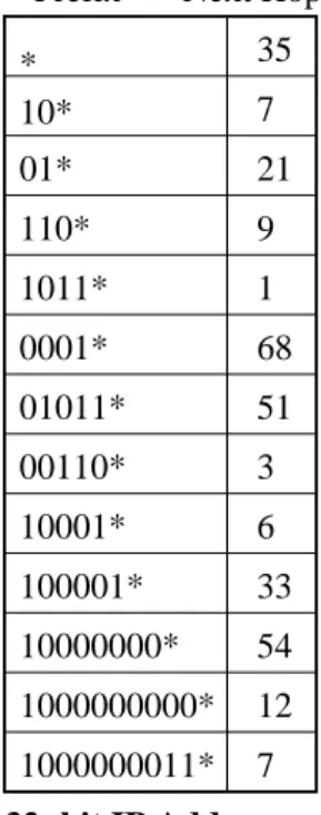
Eatherton and Dittia’s Tree Bitmap algorithm is a hardware based algorithm that employs a multibit trie data structure to perform IP forwarding lookups with efficient use of mem-ory [2]. Due to the use of CIDR, a lookup consists of finding the longest matching prefix stored in the forwarding table for a given 32-bit IPv4 destination address and retrieving the associ-ated forwarding information. As shown in Figure 1, the unicast IP address is compared to the stored prefixes starting with the most significant bit. In this example, a packet is bound for a workstation at Washington University in Saint Louis. A linear
search through the table results in three matching prefixes: *, 10*, and 1000000011*. The third prefix is the longest match, hence its associated forwarding information, denoted by Next Hop 7 in the example, is retrieved. Using this forwarding in-formation, the packet is forwarded to the specified next hop by modifying the packet header.
12
54
33
35
7
6
128.252.153.160
1000 0000 1111 1100 ... 1010 0000
*
10*
01*
0001*
01011*
00110*
Prefix
Next Hop
10001*
1000000011*
1000000000*
10000000*
100001*
7
32−bit IP Address
Next Hop
110*
1
7
9
3
1011*
68
21
51
Fig. 1. IP prefix lookup table of next hops. Next hops for IP packets are found using the longest matching prefix in the table for the unicast destination address of the IP packet.
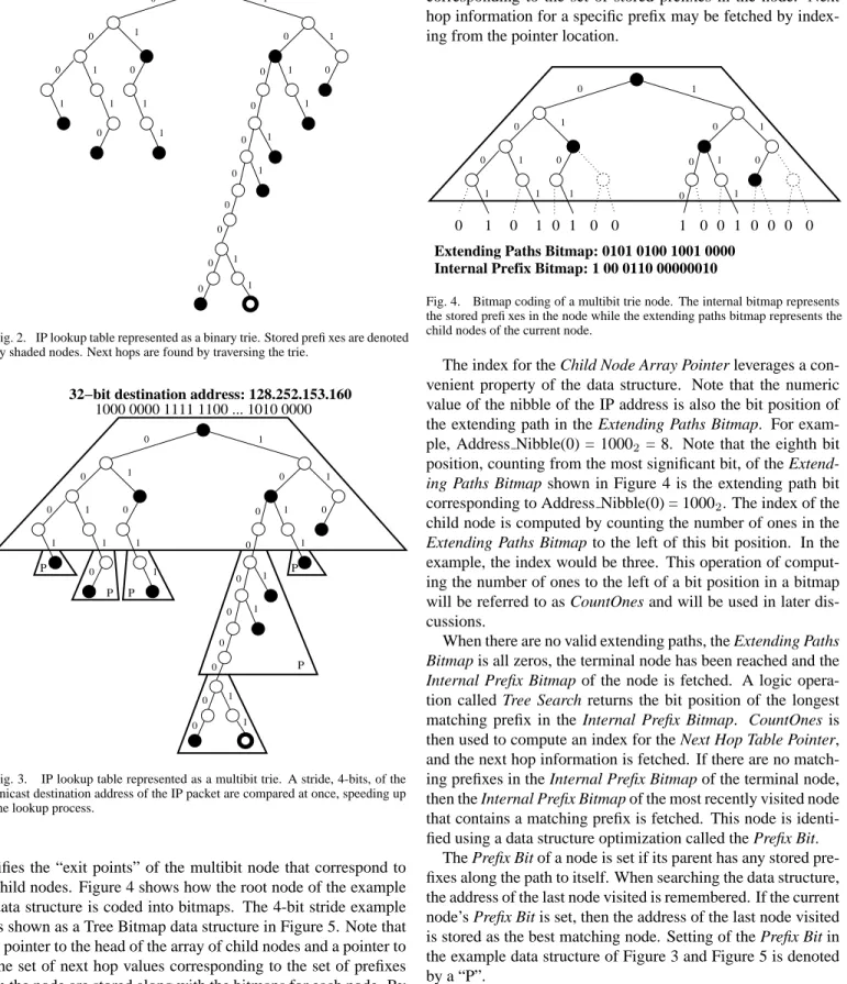
To efficiently perform this lookup function in hardware, the Tree Bitmap algorithm starts by storing prefixes in a binary trie as shown in Figure 2. Shaded nodes denote a stored prefix. A search is conducted by using the IP address bits to traverse the trie, starting with the most significant bit of the address. To speed up this searching process, multiple bits of the des-tination address are compared simultaneously. In order to do this, subtrees of the binary trie are combined into single nodes producing a multibit trie; this reduces the number of memory accesses needed to perform a lookup. The depth of the subtrees combined to form a single multibit trie node is called the stride. An example of a multibit trie using 4-bit strides is shown in Figure 3. In this case, 4-bit nibbles of the destination address are used to traverse the multibit trie. Address Nibble(0) of the
address, 10002 in the example, is used for the root node;
Ad-dress Nibble(1) of the adAd-dress, 00002 in the example, is used
for the next node; etc.
The Tree Bitmap algorithm codes information associated with each node of the multibit trie using bitmaps. The Internal
Prefix Bitmap identifies the stored prefixes in the binary
iden-0 1 1 1 0 0 0 0 1 1 1 1 1 1 0 0 1 0 0 0 0 0 1 1 1 1 0 0 0
32−bit destination address: 128.252.153.160
1000 0000 1111 1100 ... 1010 0000
Fig. 2. IP lookup table represented as a binary trie. Stored prefixes are denoted by shaded nodes. Next hops are found by traversing the trie.
P P P P P 0 1 1 1 0 0 0 0 1 1 1 1 1 1 0 0 1 0 0 0 0 0 1 1 1 1 0 0 0
32−bit destination address: 128.252.153.160
1000 0000 1111 1100 ... 1010 0000
Fig. 3. IP lookup table represented as a multibit trie. A stride, 4-bits, of the unicast destination address of the IP packet are compared at once, speeding up the lookup process.
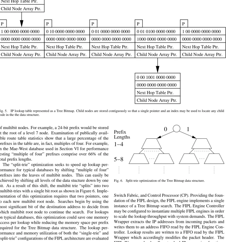
tifies the “exit points” of the multibit node that correspond to child nodes. Figure 4 shows how the root node of the example data structure is coded into bitmaps. The 4-bit stride example is shown as a Tree Bitmap data structure in Figure 5. Note that a pointer to the head of the array of child nodes and a pointer to the set of next hop values corresponding to the set of prefixes in the node are stored along with the bitmaps for each node. By requiring that all child nodes of a single parent node be stored contiguously in memory, the address of a child node can be cal-culated using a single Child Node Array Pointer and an index into that array computed from the extending paths bitmap. The same technique is used to find the associated next hop
informa-tion for a stored prefix in the node. The Next Hop Table Pointer points to the beginning of the contiguous set of next hop values corresponding to the set of stored prefixes in the node. Next hop information for a specific prefix may be fetched by index-ing from the pointer location.
Internal Prefix Bitmap: 1 00 0110 00000010 Extending Paths Bitmap: 0101 0100 1001 0000
0 0 0 0 1 0 0 1 0 0 1 0 1 0 1 0 0 0 0 1 1 1 1 1 1 0 0 0 0 1 1 1 0
Fig. 4. Bitmap coding of a multibit trie node. The internal bitmap represents the stored prefixes in the node while the extending paths bitmap represents the child nodes of the current node.
The index for the Child Node Array Pointer leverages a con-venient property of the data structure. Note that the numeric value of the nibble of the IP address is also the bit position of the extending path in the Extending Paths Bitmap. For
exam-ple, Address Nibble(0) = 10002 = 8. Note that the eighth bit
position, counting from the most significant bit, of the
Extend-ing Paths Bitmap shown in Figure 4 is the extendExtend-ing path bit
corresponding to Address Nibble(0) = 10002. The index of the
child node is computed by counting the number of ones in the
Extending Paths Bitmap to the left of this bit position. In the
example, the index would be three. This operation of comput-ing the number of ones to the left of a bit position in a bitmap will be referred to as CountOnes and will be used in later dis-cussions.
When there are no valid extending paths, the Extending Paths
Bitmap is all zeros, the terminal node has been reached and the Internal Prefix Bitmap of the node is fetched. A logic
opera-tion called Tree Search returns the bit posiopera-tion of the longest matching prefix in the Internal Prefix Bitmap. CountOnes is then used to compute an index for the Next Hop Table Pointer, and the next hop information is fetched. If there are no match-ing prefixes in the Internal Prefix Bitmap of the terminal node, then the Internal Prefix Bitmap of the most recently visited node that contains a matching prefix is fetched. This node is identi-fied using a data structure optimization called the Prefix Bit.
The Prefix Bit of a node is set if its parent has any stored pre-fixes along the path to itself. When searching the data structure, the address of the last node visited is remembered. If the current node’s Prefix Bit is set, then the address of the last node visited is stored as the best matching node. Setting of the Prefix Bit in the example data structure of Figure 3 and Figure 5 is denoted by a “P”.
A. Split-Trie Optimization
In its current configuration, which we will refer to as the “single-trie” configuration, the Tree Bitmap data structure stores prefixes with lengths that are multiples of four at the root
Child Node Array Ptr. Next Hop Table Ptr. Child Node Array Ptr.
Child Node Array Ptr. Child Node Array Ptr.
Next Hop Table Ptr. Next Hop Table Ptr.
P
Child Node Array Ptr. Next Hop Table Ptr.
Child Node Array Ptr. Next Hop Table Ptr.
Next Hop Table Ptr. Child Node Array Ptr.
P P P P
Next Hop Table Ptr.
0000 0000 0000 0000 1 00 0000 0000 0000 0000 0000 0000 0000 0 10 0000 0000 0000 0000 0000 0000 0000 0000 0000 0000 0000 0 01 0000 0000 0000 1 00 0110 0000 0010 0101 0100 0001 0000 1 00 0000 0000 0000 1000 0000 0000 0000 0 01 0100 0000 0000 0000 0000 0000 0000 0 00 1001 0000 0000
Fig. 5. IP lookup table represented as a Tree Bitmap. Child nodes are stored contiguously so that a single pointer and an index may be used to locate any child node in the the data structure.
of multibit nodes. For example, a 24-bit prefix would be stored at the root of a level 7 node. Examination of publically avail-able route tavail-able statistics show that a large percentage of the prefixes in the table are, in fact, multiples of four. For example, in the Mae-West database used in Section VI for performance testing “multiple of four” prefixes comprise over 66% of the total prefix lengths.
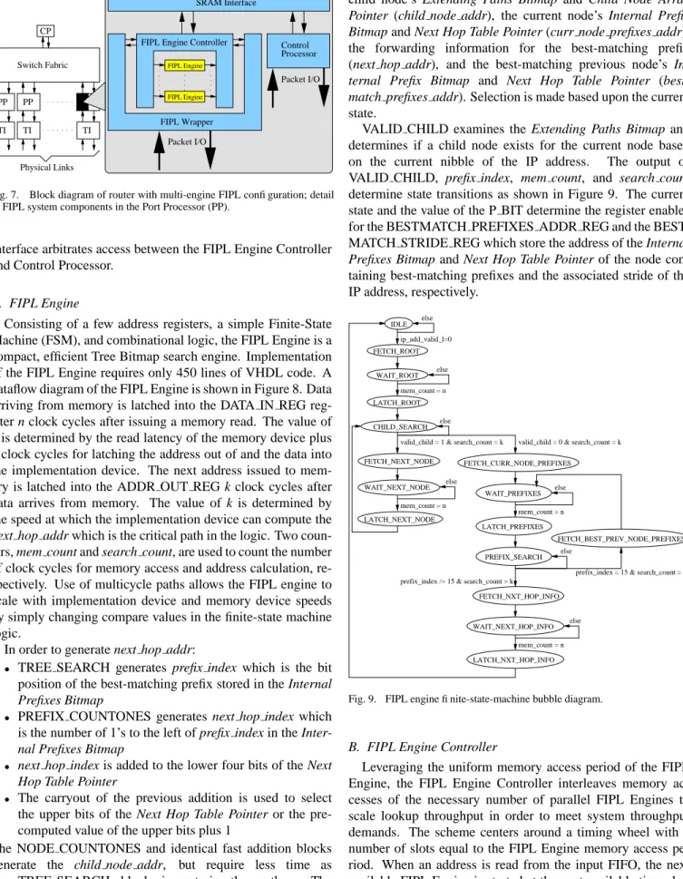
The “split-trie” optimization seeks to speed up lookup per-formance for typical databases by shifting “multiple of four” prefixes into the leaves of multibit nodes. This can easily be achieved by shifting all levels of the data stucture down by one bit. As a result of this shift, the multibit trie “splits” into two multibit-tries with a single bit root as shown in Figure 6. Imple-mentation of this optimization requires that two pointers, one to each new multibit root node. Searches begin by using the most significant bit of the destination address to decide from which multibit root node to continue the search. For lookups on typical databases, this optimization could save one memory access per lookup while reducing the memory space per prefix required for the Tree Bitmap data structure. The lookup per-formance and memory utilization of both the “single-trie” and “split-trie” configurations of the FIPL architecture are evaluated in Section VI.
IV. HARDWAREDESIGN ANDIMPLEMENTATION
Modular design techniques are employed throughout the FIPL hardware design to provide scalability for various system configurations. Figure 7 details the components required to im-plement FIPL in the Port Processor (PP) of a router. Other com-ponents of the router include the Transmission Interfaces (TI),
0
1
5−8
1−4
Prefix
Lengths
Fig. 6. Split-trie optimization of the Tree Bitmap data structure.
Switch Fabric, and Control Processor (CP). Providing the foun-dation of the FIPL design, the FIPL engine implements a single instance of a Tree Bitmap search. The FIPL Engine Controller may be configured to instantiate multiple FIPL engines in order to scale the lookup throughput with system demands. The FIPL Wrapper extracts the IP addresses from incoming packets and writes them to an address FIFO read by the FIPL Engine Con-troller. Lookup results are written to a FIFO read by the FIPL Wrapper which accordingly modifies the packet header. The FIPL Wrapper also handles standard IP processing functions such as checksums and header field updates. Specifics of the FIPL Wrapper will vary depending upon the type of switching core and transmission format. An on-chip Control Processor receives and processes memory update commands on a dedi-cated control channel. Memory updates are the result of route add, delete, or modify commands and are sent from the System Management and Control components. Note that the off-chip memory is assumed to be a single port device; hence, an SRAM
Packet I/O PP Switch Fabric Physical Links CP TI PP TI TI FIPL Engine FIPL Engine Controller
FIPL Engine FIPL Wrapper Processor Control SRAM Interface Packet I/O
Fig. 7. Block diagram of router with multi-engine FIPL configuration; detail of FIPL system components in the Port Processor (PP).
Interface arbitrates access between the FIPL Engine Controller and Control Processor.
A. FIPL Engine
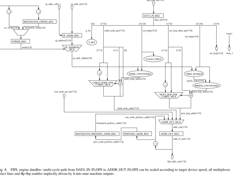
Consisting of a few address registers, a simple Finite-State Machine (FSM), and combinational logic, the FIPL Engine is a compact, efficient Tree Bitmap search engine. Implementation of the FIPL Engine requires only 450 lines of VHDL code. A dataflow diagram of the FIPL Engine is shown in Figure 8. Data arriving from memory is latched into the DATA IN REG reg-ister n clock cycles after issuing a memory read. The value of
n is determined by the read latency of the memory device plus
2 clock cycles for latching the address out of and the data into the implementation device. The next address issued to mem-ory is latched into the ADDR OUT REG k clock cycles after data arrives from memory. The value of k is determined by the speed at which the implementation device can compute the
next hop addr which is the critical path in the logic. Two
coun-ters, mem count and search count, are used to count the number of clock cycles for memory access and address calculation, re-spectively. Use of multicycle paths allows the FIPL engine to scale with implementation device and memory device speeds by simply changing compare values in the finite-state machine logic.
In order to generate next hop addr:
• TREE SEARCH generates prefix index which is the bit
position of the best-matching prefix stored in the Internal
Prefixes Bitmap
• PREFIX COUNTONES generates next hop index which
is the number of 1’s to the left of prefix index in the
Inter-nal Prefixes Bitmap
• next hop index is added to the lower four bits of the Next
Hop Table Pointer
• The carryout of the previous addition is used to select
the upper bits of the Next Hop Table Pointer or the pre-computed value of the upper bits plus 1
The NODE COUNTONES and identical fast addition blocks
generate the child node addr, but require less time as
the TREE SEARCH block is not in the path. The
ADDR OUT MUX selects the next address issued to memory among the addresses for the next root node’s Extending Paths
Bitmap and Child Node Array Pointer (root node ptr), the next
child node’s Extending Paths Bitmap and Child Node Array
Pointer (child node addr), the current node’s Internal Prefix Bitmap and Next Hop Table Pointer (curr node prefixes addr),
the forwarding information for the best-matching prefix (next hop addr), and the best-matching previous node’s
In-ternal Prefix Bitmap and Next Hop Table Pointer (best-match prefixes addr). Selection is made based upon the current
state.
VALID CHILD examines the Extending Paths Bitmap and determines if a child node exists for the current node based
on the current nibble of the IP address. The output of
VALID CHILD, prefix index, mem count, and search count determine state transitions as shown in Figure 9. The current state and the value of the P BIT determine the register enables for the BESTMATCH PREFIXES ADDR REG and the BEST-MATCH STRIDE REG which store the address of the Internal
Prefixes Bitmap and Next Hop Table Pointer of the node
con-taining best-matching prefixes and the associated stride of the IP address, respectively. FETCH_ROOT LATCH_ROOT FETCH_CURR_NODE_PREFIXES FETCH_NEXT_NODE LATCH_PREFIXES FETCH_NXT_HOP_INFO FETCH_BEST_PREV_NODE_PREFIXES LATCH_NXT_HOP_INFO IDLE else else WAIT_ROOT CHILD_SEARCH else mem_count = n ip_add_valid_l=0
valid_child = 0 & search_count = k valid_child = 1 & search_count = k
WAIT_NEXT_NODE WAIT_PREFIXES else mem_count = n else LATCH_NEXT_NODE mem_count = n PREFIX_SEARCH else
prefix_index /= 15 & search_count = k
prefix_index = 15 & search_count = k
WAIT_NEXT_HOP_INFO mem_count = n
else
Fig. 9. FIPL engine finite-state-machine bubble diagram.
B. FIPL Engine Controller
Leveraging the uniform memory access period of the FIPL Engine, the FIPL Engine Controller interleaves memory ac-cesses of the necessary number of parallel FIPL Engines to scale lookup throughput in order to meet system throughput demands. The scheme centers around a timing wheel with a number of slots equal to the FIPL Engine memory access pe-riod. When an address is read from the input FIFO, the next available FIPL Engine is started at the next available time slot. The next available time slot is determined by indexing the cur-rent slot time by the known startup latency of a FIPL Engine. For example, assume an access period of 8 clock cycles; hence,
IP_ADDR_REG IP_ADDRESS MUX VALID_CHILD ADDR_OUT_MUX ADDR_OUT_REG PREFIXES_ADDR_REG BESTMATCH_PREFIXES_ADDR_REG P_BIT DATA_IN_REG fipl_data_in[35:0] data_in[35:0] STRIDE_REG BESTMATCH_STRIDE_REG +1 −1 bestmatch_stride[3:0] nx_stride[3:0] CHILD_NODE_PTR CARRY_MUX NODE_COUNTONES +1 +1 +1 PREFIX_COUNTONES CARRY_MUX next_hop_addr[17:0] child_node_addr[17:0] bestmatch_prefixes_addr[17:0] ip_addr_in[31:0] ip_addr_valid_l ip_address[31:0]
p_bit child_node_ptr[17:0] ext_bmp[15:0] nxt_hop_table_ptr[17:0]
nxt_hop[15:0] done_l int_bmp[14:0] [34] [17:0] [33:18] [17:0] [32:18] [15:0] [17:5] [17:4] [3:0] prefix_index[3:0] fipl_addr_out[17:0] addr_ff_out[17:0] (state) root_node_ptr_in[17:0] ip_addr_nibble[3:0] stride[3:0] [4:1] child_node_index[3:0] [0] next_hop_index[3:0] prev_node_prefixes_addr[17:0] curr_node_prefixes_addr[17:0] addr_out[17:0] NEXT_HOP_PTR TREE_SEARCH
Fig. 8. FIPL engine dataflow; multi-cycle path from DATA IN FLOPS to ADDR OUT FLOPS can be scaled according to target device speed; all multiplexor select lines and flip-flop enables implicitly driven by finite-state machine outputs.
the timing wheel has 8 slots numbered 0 through 7. Assume three FIPL Engines are currently performing lookups occupy-ing slots 1, 3, and 4. Furthermore, assume that from the time the IP address is issued to the FIPL Engine to the time the FIPL Engine issues its first memory read is 2 clock cycles; hence, the startup latency is 2 slots. When a new IP address arrives, the next lookup may not be started at slot times 7, 1, or 2 because the first memory read would be issued at slot time 1, 3, or 4, respectively which would interfere with ongoing lookups. As-sume the current slot time is 3; therefore, the next FIPL engine is started and slot 5 is marked as occupied.
As previously mentioned, input IP addresses and output for-warding information are passed between the FIPL Engine Con-troller and the FIPL Wrapper via FIFO interfaces. This design simplifies the design of the FIPL Wrapper by placing the burden of in-order delivery of results on the FIPL Engine Controller. While individual input and output FIFOs could be used for each engine to prevent head-of-the-line blocking, network designers will usually choose to configure the FIPL Engine Controller as-suming worst-case lookups. Also, the performance numbers re-ported in a subsequent section show that average lookup latency per FIPL Engine increases by less than 3% for an 8-engine con-figuration; therefore, lookup engine “dead-time” is negligible.
C. Implementation Platform
FIPL is implemented on open-platform research systems de-signed and built at Washington University in Saint Louis [10]. The WUGS 20, an 8-port ATM switch providing 20 Gb/s of aggregate throughput, provides a high-performance switching fabric [11]. This switching core is based upon a multi-stage Benes topology, supports up to 2.4 Gb/s link rates, and scales up to 4096 ports for an aggregate throughput of 9.8 Tb/s [12]. Each port of the WUGS 20 can be fitted with a Field-programmable Port eXtender (FPX), a port card of the same form factor as the WUGS transmission interface cards [13]. Each FPX con-tains two FPGAs, one acting as the Network Interface Device (NID) and the other as the Reprogrammable Application De-vice (RAD).
The RAD FPGA has access to two 1MB Zero Bus Turnaround (ZBT) SRAMs and two 64MB SDRAM mod-ules providing a flexible platform for implementing high-performance networking applications [14]. To allow for packet reassembly and other processing functions requiring memory resources, the FIPL has access to one of the 8 Mbit ZBT (Zero Bus Turnaround) SRAMs which require 18-bit addresses and provide a 36-bit data path with a 2-clock cycle latency. Since this memory is ”off-chip” both the address and data lines must
be latched at the pads of the FPGA, providing for a total latency to memory of n = 4 clock cycles.
D. Memory Configuration
Utilizing a 4-bit stride the Extending Paths Bitmap is 16-bits long, occupying less than a half-word of memory. The remaining 20-bits of the word are used for the Prefix Bit and
Child Node Array Pointer; hence, only one memory access is
required per node when searching for the terminal node. Like-wise, the Internal Prefix Bitmap and Next Hop Table Pointer may be stored in a single 36-bit word; hence, a single node of the Tree Bitmap requires two words of memory space. 131,072 nodes may be stored in one of the 8Mbit SRAMs providing a maximum of 1,966,080 stored routes. Note that the memory usage per route entry is dependent upon the distribution of pre-fixes in the data structure. Memory usage for the experimental data structure is reported in the Section VI.
E. Worst-Case Performance
In this configuration, the pathological lookup requires 11 memory accesses: 8 memory accesses to reach the terminal node, 1 memory access to search the sub-tree of the terminal node, 1 memory access to search the sub-tree of the most re-cent node containing a match, and 1 memory access to fetch the forwarding information associated with the best-matching prefix. Since the FPGAs and SRAMs run on a synchronous 100MHz clock, all single cycle calculations must be completed in less than 10ns. The critical path in the FIPL design, re-solving the next hop addr, requires more than 20 ns when tar-geted to the RAD FPGA of the FPX, a Xilinx XCV1000E-7;
hence,kis set to 3. This provides a total memory access period
of 80 ns and requires 8 FIPL engines in order to fully utilize the available memory bandwidth. Theoretical worst-case per-formance, all lookups requiring 11 memory accesses, ranges from 1,136,363 lookups per second for a single FIPL engine to 9,090,909 lookups per second for eight FIPL engines in this implementation environment.
F. Hardware Resource Usage
As the WUGS 20 supports a maximum line speed of 2.4 Gb/s, a 4-engine configuration is used in the Washington
Uni-versity system. Due to the ATM switching core, the FIPL
Wrapper supports AAL5 encapsulation of IP packets inside of ATM cells [15]. Relative to the Xilinx Virtex 1000E FPGA used in the FPX, each FIPL Engine utilizes less than 1% of the available logic resources. Configured with 4 FIPL Engines, FIPL Engine Controller utilizes approximately 6% of the logic resources while the FIPL Wrapper utilizes another 2% of the logic resources and 12.5% of the on-chip memory resources. This results in an 8% total logic resource consumption by FIPL. The SRAM Interface and Control Processor which parses con-trol cells and executes memory commands for route updates utilize another 8% of the available logic resources and 2% of the on-chip memory resources. Therefore, all input IP forward-ing functions occupy 16% of the logic resources leavforward-ing the re-maining 84% of the device available for other packet processing functionality. SRAM FPGA FPGA RAD OC−3 Link VCI 76 (NID), VCI 100 (RAD)
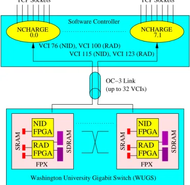
NID SDRAM FPX RAD FPGA 0.0 NCHARGE 7.1 FPX SDRAM NID FPGA NCHARGE SRAM
Washington University Gigabit Switch (WUGS)
TCP Sockets TCP Sockets
Software Controller
VCI 115 (NID), VCI 123 (RAD)
(up to 32 VCIs)
Fig. 10. Control of the Field-programmable Port eXtender (FPX) via NCHARGE software. Each FPX is controlled by an instance of NCHARGE which provides an API for FPX control via remote software process.
V. SYSTEMMANAGEMENT ANDCONTROLCOMPONENTS
System management and control of FIPL in the Washington University system is performed by several distributed compo-nents. All components were developed to facilitate further re-search using the open-platform system.
A. NCHARGE
NCHARGE is the software component that controls repro-grammable hardware on a switch [16]. Figure 10 shows the role of NCHARGE in conjunction with multiple FPX devices within a switch. The software provides connectivity between each FPX and multiple remote software processes via TCP sockets that listen on a well-defined port. Through this port, other soft-ware components are able to communicate to the FPX using its specified API. Because each FPX is controlled by an indepen-dent NCHARGE software process, distributed management of entire systems can be performed by collecting data from multi-ple NCHARGE elements. [17].
B. FIPL Memory Manager
The FIPL Memory Manager is a stand alone C++ application that accepts commands to add, delete, and update routing en-tries for a hardware-based Internet router. The program main-tains the previously discussed Tree Bitmap data structure in a shared memory between hardware and software . When a user enters route updates, the FIPL Memory Manager Software re-turns the corresponding memory updates needed to perform that operation in the FPX hardware.
Command options: [A]dd [D]elete
[C]hange [P]rint [M]emoryDump [Q]uit
Enter command (h for help): A You entered add
Enter prefix x.x.x.x/s
(x = 0-255, s is significant bits 0-32) : 192.128.1.1/8
Enter Next Hop value: 4 ******
Memory Update Commands:
w36 0 4 2 000000000 100000006 w36 0 2 2 200000004 000000000 w36 0 0 2 000200002 000000000
In the example shown here a single add route command re-quires three 36-bit memory write commands, each consisting of 2 consecutive locations in memory at addresses 4, 2, and 0, respectively.
C. Sockets Interfaces
In order to access the FIPL Memory Manager as a daemon process, support software needs to be in place to handle stan-dard input and output. Socket software was developed to han-dle incoming route updates to pass along to the FIPL Memory Manager. A socket interface was also developed to send the re-sulting output of a memory update to the NCHARGE software. These software processes handling input and output are called Write Fip and Read Fip, respectively. Write Fip is constantly listening on a well known port for incoming route update com-mands. Once a connection is established the update command is sent as an ASCII character string to Write Fip. This soft-ware prints the string as standard output which is redirected to the standard input of FIPL Memory Manager. The memory up-date commands needed by NCHARGE software to perform the route update are issued at the output of FIPL Memory Manager. Read Fip receives these commands as standard input and sends all of the memory updates associated with one route update over a TCP socket to the NCHARGE software.
D. Remote User Interface
The current interface for performing route updates is via a web page that provides a simple interface for user interaction. The user is able to submit single route updates or a batch job of multiple routes in a file. Another option available to users is the ability to define unique control cells. This is done through the use of software modules that are loaded into the NCHARGE system.
In the current FIPL Module, a web page has been designed to provide a simple interface for issuing FIPL control commands, such as changing the Root Node Pointer. The web page also provides access to a vast database of sample route table entries
FAST IP LOOKUP Port Number: Stack Level:
Route Add
IP Address: Net Mask: Next Hop: Route Delete
IP Address: Net Mask:
Route Modify
IP Address: Net Mask: Next Hop:
Submit Routes Filename: !"!"#%$'&
Fig. 12. FPX Web Interface for FIPL route updates.
taken from the Internet Performance Measurement and Anal-ysis project’s website [18]. This website provides daily snap-shots of Internet backbone routing tables including traditional Class A, B, and C addresses. Selecting the download option from the FIPL web page executes a Perl script to fetch the router snapshots from the database. The Perl script then parses the files and generates an output file that is readable by the Fast IP Lookup Memory Manager.
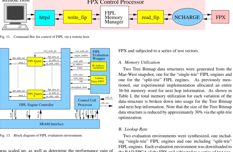
E. Command Flow
The overall flow of data with FIPL and NCHARGE is shown in Figure 11. Suppose a user wishes to add a route to the database. The user first submits either a single command or sub-mits a file containing multiple route updates. Data submitted from the web page, Figure 12, is passed to the Web Server as a form. Local scripts process the form and generate an Add Route command that the software understands. These commands are ASCII strings in the form “Add routeA1.A2.A3.A4/netmask nexthop”. The script then sets up a TCP Socket and transmits each command to the Write Fip software process. As men-tioned before Write fip listens on a TCP port and relays mes-sages to standard output in order to communicate with the FIPL Memory Manager. FIPL Memory Manager takes the standard input and processes the route command in order to generate memory updates for an FPX board. Each memory update is then passed as standard output to the Read Fip process.
After this process collects memory updates it establishes a TCP connection with NCHARGE to transmit the commands. Read Fip is able to detect individual route commands and is-sues the set of memory updates associated with each. This pre-vents Read Fip from creating a socket for every memory up-date. From here memory updates are sent to NCHARGE soft-ware process to be packed into control cells to send to the FPX. NCHARGE packs as many memory commands as it can fit into a 53 byte ATM cell while preserving order between commands. NCHARGE sends these control cells using a stop-and-wait pro-tocol to ensure correctness, then issues a response message to the user.
VI. PERFORMANCEMEASUREMENTS
While the worst-case performance of FIPL is deterministic, an evaluation environment was developed in order to bench-mark average FIPL performance on actual router databases. The evaluation environment was used to extract lookup and update performance as the number of parallel FIPL Engines
Manager
Memory
FIPL
FPX
read_fip
write_fip
httpd
NCHARGE
FPX Control Processor
Remote Host
Fig. 11. Command flow for control of FIPL via a remote host.
FIPL Engine Controller
grant request
FIPL
rw
address data_out data_in grant request address data_in
SRAM Interface ip_addr_valid ip_addr_in fipl_data_in done_l fipl_addr_out Processor Control Cell root_node_ptr ip_addr_valid ip_addr_in fipl_data_in done_l fipl_addr_out FIPL Engine FIPL Engine 1 8 cells_in cells_out read_addr ip_address empty write_time write_data full engine_enables root_node_ptr throughput_timer Latency Timer FIFO IP Address Generator Wrapper Evaluation
Fig. 13. Block diagram of FIPL evaluation environment.
was scaled up, as well as determine the performance gain of the split-trie optimization. As shown in Figure 13, the evalua-tion environment includes a modified FIPL Engine Controller, 8 FIPL Engines, and a FIPL Evaluation Wrapper. The FIPL Eval-uation Wrapper includes an IP Address Generator which uses on-chip BlockRAMs in the Xilinx FPGA to implement storage for 16,384 IPv4 destination addresses. The IP Address Genera-tor interfaces to the FIPL Engine controller like a FIFO. When a test run is initiated, an empty flag is driven to FALSE until all 16,384 addresses are read.
Control cells sent to the FIPL Evaluation Wrapper initiate test runs of 16,384 lookups and specify how many FIPL En-gines should be used during the test run. The FIPL Engine Controller contains a latency timer for each FIPL Engine and a throughput timer that measure the number of clock cycles required to complete each lookup and the test run of 16,384 addresses, respectively. Latency timer values are written to a FIFO upon completion of each lookup. The FIPL Evaluation Wrapper packs latency timer values into control cells which are sent back to the system control software where the contents are dumped to a file. The throughput timer value is included in the final control cell.
A snapshot of the Mae-West database from March 15, 2002 consisting of 27,609 routes was used for all tests. The on-chip memory read by the IP Address Generator was initialized with 16,384 IPv4 destination addresses created via random selec-tions from the route table snapshot. Two evaluation environ-ments were synthesized, one including “single-trie” FIPL en-gines and one including “split-trie” FIPL enen-gines. Each eval-uation environment was downloaded to the RAD FPGA of the
FPX and subjected to a series of test vectors.
A. Memory Utilization
Two Tree Bitmap data structures were generated from the Mae-West snapshot, one for the “single-trie” FIPL engines and
one for the “split-trie” FIPL engines. As previously
men-tioned, our experimental implementation allocated an entire 36-bit memory word for next hop information. As shown in Table I, the total memory utilization for each variation of the data-structure is broken down into usage for the Tree Bitmap and next hop information. Note that the size of the Tree Bitmap data structure is reduced by approximately 30% via the split-trie optimization.
B. Lookup Rate
Two evaluation environments were synthesized, one includ-ing “sinclud-ingle-trie” FIPL engines and one includinclud-ing “split-trie” FIPL engines. Each evaluation environment was downloaded to the RAD FPGA of the FPX and subjected to a series of test vec-tors. The Tree Bitmap data structure generated from the Mae-West database of 27,609 routes was loaded into the off-chip SRAM. The on-chip memory read by the IP Address Generator was initialized with 16,384 IPv4 destination addresses created via random selections from the route table snapshot. Test runs were initiated using configurations of 1 through 8 engines.
Each evaluation environment was first tested with no inter-vening updates. Figure 14 plots the number of lookups per sec-ond versus the number of parallel FIPL engines for the single-trie and split-single-trie versions. The theoretical worst-case perfor-mance is also included for reference. With no intervening up-date traffic, lookup throughput for the “single-trie” configura-tion ranged from 1.46 million lookups per second for a single FIPL engine to 10.09 million lookups per second for 8 FIPL engines; an 11% increase in performance over the theoretical worst-case. Under identical conditions, lookup throughput for the “split-trie” configuration ranged from 1.58 million lookups per second for a single FIPL engine to 11 million lookups per second for 8 FIPL engines; a 9% increase in performance over the “single-trie” configuration. Average lookup latency for “single-trie” FIPL engines ranged from 656 ns for a single FIPL engine to 674 ns for 8 FIPL engines. Average lookup latency for “split-trie” FIPL engines ranged from 603 ns for a single FIPL engine to 619 ns for 8 FIPL engines.
In order to evaluate performance under update load, updates were transmitted to the evaluation environment at various rates during test runs. Update traffic consisted of an alternating pat-tern of a 24-bit prefix add a 24-bit prefix delete. For the the “single-trie” configuration, the 24-bit prefix add required 25
TABLE I
MEMORY USAGE FOR THETREEBITMAP DATA STRUCTURE AND NEXT HOP INFORMATION USING A SNAPSHOT OF THEMAE-WEST DATABASE FROM MARCH15, 2002CONSISTING OF27,609ROUTES.
Type Total Total Next Hop Next Hop Tree Bitmap Tree Bitmap
(bytes) (bytes/prefix) (bytes) (bytes/prefix) (bytes) (bytes/prefix)
Single-Trie 409,937 14.8 124,241 4.5 285,696 10.3 Split-Trie 298,822 10.8 124,241 4.5 174,582 6.3 0 1 2 3 4 5 6 7 8 9 10 11 12 1 2 3 4 5 6 7 8 # of FIPL engines M il li o n s o f lo o k u p s p er s ec o n d
Mae-West Throughput (Split Tree)
Mae-West Throughput
Theoretical Worst-case Throughput
Fig. 14. FIPL performance: measurements used a snapshot of the Mae-West database from March 15, 2002 consisting of 27,609 routes. Input IPv4 desti-nation addresses were created by randomly selecting 16,384 prefixes from the Mae-West database.
memory write operations which were packed into 4 control cells. The 24-bit prefix delete required 14 memory write opera-tions which were packed into 3 control cells. For the the “split-trie” configuration, the 24-bit prefix add required 21 memory write operations which were packed into 4 control cells. The 24-bit prefix delete required 12 memory write operations which were packed into 2 control cells. Test runs were executed for both configurations with updates rates ranging from 1,000 up-dates per second to 1,000,000 upup-dates per second. Note that the upper end of the range, one update per microsecond, repre-sents a highly unrealistic situation as update frequencies rarely exceed 1,000 updates per second.
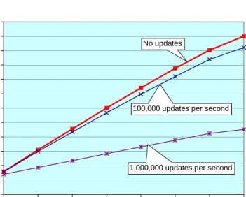
Results of test runs of the “single-trie” FIPL configuration with intervening update traffic are shown in Figure 15. Results of test runs of the “split-trie” FIPL configuration with interven-ing update traffic are shown in Figure 16. For both configura-tions, update frequencies up to 10,000 updates per second had no noticeable effect on lookup throughput performance. For an update frequency of 100,000 updates per second, the “single-trie” configuration exhibited a maximum performance degrada-tion of 6.5% while the “split-trie” throughput was reduced by 7.2%. For an update frequency of 1,000,000 updates per sec-ond, the “single-trie” configuration exhibited a maximum per-formance degradation of 56% while the “split-trie” throughput was reduced by 58.9%. FIPL not only demonstrates no notice-able performance degradation under normal update loads, but it also remains robust under excessive update loads.
0 1 2 3 4 5 6 7 8 9 10 11 12 1 2 3 4 5 6 7 8 # of FIPL engines M il li o n s o f lo o k u p s p er s ec o n d No updates
100,000 updates per second
1,000,000 updates per second
Fig. 15. FIPL performance under update load: measurements used a snapshot of the Mae West database from March 15, 2002 consisting of 27,609 routes. Input IPv4 destination addresses were created by randomly selecting 16,384 prefixes from the Mae-West database. Updates consisted of alternating addition and deletion of a 24-bit prefix.
0 1 2 3 4 5 6 7 8 9 10 11 12 1 2 3 4 5 6 7 8 # of FIPL engines M il li o n s o f lo o k u p s p er s ec o n d No updates
100,000 updates per second
1,000,000 updates per second
Fig. 16. FIPL Split-Trie performance under update load: measurements used a snapshot of the Mae West database from March 15, 2002 consisting of 27,609 routes. Input IPv4 destination addresses were created by randomly selecting 16,384 prefixes from the Mae-West database. Updates consisted of alternating addition and deletion of a 24-bit prefix.
Based on the test results, a FIPL configuration employ-ing four parallel search engines was synthesized for the WUGS/FPX research platform in order to support 2 Gb/s links. Utilizing custom traffic generators and bandwidth monitoring software, throughput for minimum length packets was mea-sured at 1.988 Gb/s. Note that the total system throughput is limited by the 32-bit WUGS/FPX interface operating at 62.5 MHz. Additional tests injected route updates to measure update performance while maintaining 2 Gb/s of offered lookup traffic. The FIPL configuration experienced only 12% perfor-mance degradation at update rates of 200,000 updates per sec-ond.
VII. TOWARDSBETTERPERFORMANCE
Ongoing research efforts seek to leverage the components and insights gained from implementing Fast IP Lookup (FIPL) on the open research platforms developed at Washington Uni-versity. The first effort works to increase the performance of FIPL via design and device optimizations. Other efforts seek to increase the performance and efficiency of FIPL via data struc-ture optimizations to reduce off-chip memory accesses. Finally, FIPL search engines are being incorporated into a classification and route lookup system for the multi-service router project at Washington University [3].
A. Implementation Optimizations
Coupled with advances in FPGA device technology, imple-mentation optimizations of critical paths in the FIPL engine cir-cuit hold promise of increasing the system clock frequency in order to take full advantage of the memory bandwidth offered by modern SRAMs. Existing DDR SRAMs are capable of op-erating at 200 MHz with the equivalent of two read operations per cycle. Note that modern FPGAs are capable of running at this frequency and no throughput is gained via an ASIC imple-mentation since off-chip SRAM accesses are the performance bottleneck. Doubling of the clock frequency of FIPL, employ-ing 16 engines, and usemploy-ing a DDR SRAM directly translates to a factor of four increase in lookup performance to a guaranteed worst case throughput of over 36.4 million lookups per second.
B. Root Node Extension & Caching
By both caching the root node and extending its stride length, the number of off-chip memory accesses can be reduced. Ex-tending the stride length of the root node increases the num-ber of bits required for the extending paths and internal prefix bitmaps. The increase in the number of extending paths also requires a larger chunk of contiguous memory for storing the child node array. In general, the number of bitmap bits required for a stride of length n is2n+1
−1. The maximum number of
contiguous memory spaces needed for the child node array is
2n
.
Selecting the stride length for the cached root node mainly depends upon the amount of available on-chip memory and logic. In the case of ample on-chip memory, one would still want to bound the stride length to prevent the amount of con-tiguous memory spaces necessary for the child node array from
Next Hop Next Hop Next Hop
Next Hop
Destination Address [31:i]
Fig. 17. Root node extension using an on-chip array and multiple sub-tries.
becoming too large. Selection of a stride length which is a factor of four plus one (i.e. 5, 9, 13, ...) provides the favor-able property of implementing the exact match case efficiently. Normally, the exact match case requires either the optimiza-tion of nodes of depth eight or the addioptimiza-tion of leaf nodes stor-ing a sstor-ingle prefix. Selectstor-ing a root node stride length of eight requires extending paths and internal prefix bitmap lengths of 8192 and 8191 bits, respectively. Given that current generations of FPGAs implement 16kb blocks of memory, the bitmap stor-age requirement does not seem prohibitively high. However, the CountOnes and Tree Search functions consume exorbitant amounts of logic for such large bitmaps.
Another approach is to simply represent the root node as an
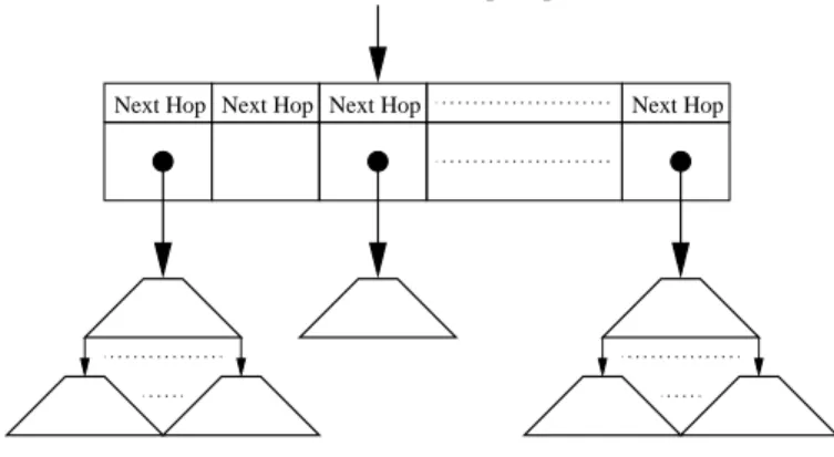
on-chip array indexed by the firstibits of the destination
ad-dress, where i is determined by the stride length of the root
node. As shown in 17, each array entry stores the next hop information for the best-matching prefix in the n-bit path rep-resented by the index, as well as a pointer to an extending path sub-tree. Searches simply examine the extending path sub-tree pointer to see if a sub-tree exists for the given address. This may be done by designating a null pointer value or using a valid ex-tending path bit. If no exex-tending path sub-tree exists, the next hop information stored in the on-chip array entry is applied to the packet. If an extending path sub-tree exists, the extending path sub-tree pointer is used to fetch the “root node” of the ex-tending path sub-tree and the search continues in the normal Tree Bitmap fashion. If no matching prefix is found in the sub-tree, the next hop information stored in the on-chip array entry is applied to the packet.
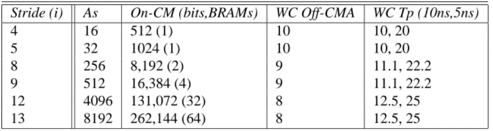
Obviously, the performance gain comes at the cost of on-chip resource usage. Table II shows the following:
• Array Size (AS): number of array slots.
• On-chip Memory (On-CM): the amount of on-chip mem-ory needed (in terms of bits and number of BlockRAMs required in the Virtex-E target device) in order to allocate the root node array.
• Worst Case Off-chip Memory Accesses (WC Off-CMA): the amount of off-chip memory required to store sub-trees. • Worst Case Throughput (WC Tp): millions of lookups per
second assuming a 100MHz clock (T=10ns) and 200MHz clock (T=5ns).
Note it is assumed that all sub-tree pointers and next hop in-formation are 16-bits each. If more next-hop inin-formation is
TABLE II
MEMORY USAGE FOR ROOT NODE ARRAY OPTIMIZATION.
Stride (i) As On-CM (bits,BRAMs) WC Off-CMA WC Tp (10ns,5ns)
4 16 512 (1) 10 10, 20 5 32 1024 (1) 10 10, 20 8 256 8,192 (2) 9 11.1, 22.2 9 512 16,384 (4) 9 11.1, 22.2 12 4096 131,072 (32) 8 12.5, 25 13 8192 262,144 (64) 8 12.5, 25
required, the on-chip memory may be scaled accordingly or the information may be stored off-chip and the 16-bit field used as a pointer.
Future research will seek to more fully characterize this de-sign option by determining the following:
• On-chip Memory Usage (On-CMU): the number and per-centage of occupied array slots.
• Off-chip Memory Usage (Off-CMU): the amount of off-chip memory required to store sub-trees.
• Throughput (Tp): lookups per second when using a back-bone routing table snapshot.
VIII. CONCLUSIONS
IP address lookup is one of the primary functions of the router and often is a significant performance bottleneck. In re-sponse, we have presented the Fast Internet Protocol Lookup (FIPL) architecture which utilizes Eatherton and Dittia’s Tree Bitmap algorithm. Striking a favorable balance between lookup and update performance, memory efficiency, and hardware re-source usage, each FIPL engine supports over 500 Gb/s of link traffic while consuming less than 1% of available logic resources and approximately 10 bytes of memory per entry. Utilizing only a fraction of a reconfigurable logic device and a single commodity SRAM, FIPL offers an attractive alternative to expensive commercial solutions employing multiple Content Addressable Memory (CAM) devices and Application Specific Integrated Circuits (ASICs). By providing high-performance at low per-port costs, FIPL is a prime candidate for System-On-Chip (SoC) solutions for efficient next-generation Internet routers.
ACKNOWLEDGMENTS
We would like to acknowledge William Eatherton and Zubin Dittia as the developers of the Tree Bitmap algorithm. Their design efforts and analyses made this research possible. We also would like to thank Tucker Evans and Ed Spitznagel for their contributions to the FIPL Memory Manager software, as well as John DeHart for his invaluable assistance with system verification and performance measurements.
REFERENCES
[1] S. Fuller, T. Li, J. Yu, and K. Varadhan, “Classless inter-domain rout-ing (CIDR): an address assignment and aggregation strategy,” RFC 1519, September 1993.
[2] W. N. Eatherton, “Hardware-Based Internet Protocol Prefix Lookups,” thesis, Washington University in St. Louis, 1998.
[3] Sumi Choi, John Dehart, Ralph Keller, Fred Kuhns, John Lockwood, Prashanth Pappu, Jyoti Parwatikar, W. David Richard, Ed Spitznagel, David Taylor, Jonathan Turner, , and Ken Wong, “Design of a High Per-formance Dynamically Extensible Router,” in DARPA Active Networks
Conference and Exposition, May 2002.
[4] Pankaj Gupta, Steven Lin, and Nick McKeown, “Routing lookups in hardware at memory access speeds,” in IEEE Infocom, 1998.
[5] S. Nilsson and G. Karlsson, “Fast address lookup for Internet routers,” in
IFIP International Conference of Broadband Communications, 1998.
[6] V. Srinivasan and G. Varghese, “Faster ip lookups using controlled prefix expansion,” in SIGMETRICS, 1998.
[7] M. Degermark, A. Brodnik, S. Carlsson, and S. Pink, “Small forwarding tables for fast routing lookups,” in ACM Sigcomm, 1997.
[8] SiberCore Technologies Inc., “SiberCAM Ultra-2M SCT2000,” Product Brief, 2000.
[9] Marcel Waldvogel, George Varghese, Jon Turner, and Bernhard Plattner, “Scalable high speed IP routing table lookups,” in Proceedings of ACM
SIGCOMM ’97, September 1997, pp. 25–36.
[10] Jonathan S. Turner, “Gigabit Technology Distribution Program,”
http://www.arl.wustl.edu/gigabitkits/kits.html, Aug. 1999.
[11] J. Turner, T. Chaney, A. Fingerhut, and M. Flucke, “Design of a Gigabit ATM Switch,” in In Proceedings of Infocom 97, Mar. 1997.
[12] Sumi Choi, John Dehart, Ralph Keller, John W. Lockwood, Jonathan Turner, and Tilman Wolf, “Design of a flexible open platform for high performance active networks,” in Allerton Conference, Champaign, IL, 1999.
[13] John W. Lockwood, Jon S. Turner, and David E. Taylor, “Field pro-grammable port extender (FPX) for distributed routing and queuing,” in ACM International Symposium on Field Programmable Gate Arrays
(FPGA’2000), Monterey, CA, USA, Feb. 2000, pp. 137–144.
[14] John W. Lockwood, Naji Naufel, Jon S. Turner, and David E. Taylor, “Re-programmable Network Packet Processing on the Field Programmable Port Extender (FPX),” in ACM International Symposium on Field
Pro-grammable Gate Arrays (FPGA’2001), Monterey, CA, USA, Feb. 2001,
pp. 87–93.
[15] Peter Newman et al., “Transmission of flow labelled IPv4 on ATM data links,” Internet RFC 1954, May 1996.
[16] Todd S. Sproull, John W. Lockwood, and David E. Taylor, “Control and Configuration Software for a Reconfigurable Networking Hardware Plat-form,” in FCCM’02: 2002 IEEE Symposium on Field-Programmable
Custom Computing Machines, April 2002.
[17] James M. Anderson, Mohammad Ilyas, and Sam Hsu, “Distributed net-work management in an internet environment,” in Globecom’97, Pheonix, AZ, Nov. 1997, vol. 1, pp. 180–184.
[18] “Internet Routing Table Statistics,” http://www.merit.edu-/ipma/routing_table/, May 2001.