Requirements by Contracts allow Automated System Testing
Clémentine Nebut, Franck Fleurey, Yves Le Traon and Jean-Marc Jézéquel
IRISA-Université de Rennes 1,
Campus Universitaire de Beaulieu,
35042 Rennes Cedex, France
{Clementine.Nebut, Franck.Fleurey, Yves.Le_Traon, Jean-Marc.Jezequel}@irisa.fr
Abstract
Use-cases and scenarios have been identified as good in-puts to generate test cases and oracles at requirement level. Yet to have an automated generation, information is missing from use cases and sequence diagrams, such as the exact inputs of the system, and the ordering constraints between the use case. The contribution of this paper is then two-fold. First we propose a contract language for functional requirements expressed as parameterized use cases. Then we provide a method, a formal model and a prototype tool to automatically derive both functional and robustness test cases from the requirements enhanced with contracts. We study the efficiency of the generated test cases on a case study.
1
Introduction
The conclusion of a survey [17] of industrial software projects insists on the industrial need to base system tests on use cases and scenarios. However, most projects lack a systematic approach for defining test cases based on func-tional requirements, expressed within the UML with use cases. Important benefits are expected from expressing and deriving functional test objectives at this level. Time-to-market constraints are easier to satisfy since integration and unit test stages are lightened. Moreover, the consistency be-tween requirements and implementation is guaranteed, and test objectives are more reusable than code specific tests in the case of software evolution. While in the literature, it is admitted that use-cases and scenarios offer a good input to generate test cases and oracles [16, 14, 3, 4], many ob-stacles remain, that have been identified by Binder [2] in terms of three questions : How do I choose test cases? ;
In what order should I apply my tests? ; How do I know when I’m done?The first question concerns the domain def-inition of inputs and output variables at requirement level. The second one concerns the generation of test cases that
are consistent with sequential constraints, and the last one concerns the definition of a non-ambiguous test adequacy criterion. To our knowledge, the only work in that direction is Briand’s one [3, 4] with a complete system-based testing methodology. In this paper, we go along the same lines and focus on requirement-based testing and not on system test-ing in the sense we want our approach to be independent from analysis and design steps. We propose a systematic requirement-by-contract approach, close to the design-by-contract approach proposed in [10], except that logical ex-pression are very simple to fit with requirement level of pre-ciseness. This approach answers Binder’s problematic by identifying in the contracts the variables involved in testing, by generating a formal representation of all valid use-cases sequences (with a labeled transition system model) and by proposing, for this representation, coverage criteria, unam-biguous and intuitively meaningful. The key question we address here is to determine whether test cases generated at very high level are still relevant at code-level. Secondary issues also addressed in this paper concern which criteria may be the most efficient to generate test objectives, and an evaluation of using activity diagrams for requirement-based testing.
The rest of the paper is organized as follows. Section 2 presents a contract language for requirements and illus-trates it on a case study. Section 3 details the generation of functional test objectives from requirements enhanced with contracts. This generation is based on a use case la-beled transition system, and we propose test coverage cri-teria to extract test objectives from this model. Section 4 explains how this generation can be extended to automated robustness test generation, with a complementary criterion. Section 5 is an experimental part aiming at studying the ef-fectiveness of generated test cases on a case study, and at comparing it with another approach based on activity dia-grams. Section 6 and 7 state the related work and give our conclusions and future work.
2
A contract language for requirements
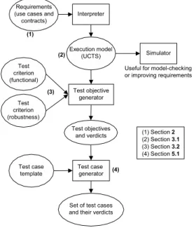
In this section, we present a way to express the sequential constraints existing between the use cases of an application, remaining within the UML. This approach proposes to as-sociate contracts – i.e. pre and post conditions – to each use case, in the form of logical expressions. Such contracts allow the designer to express for each use case both the sys-tem properties making it applicable, and the properties ac-quired by the system after its application. This approach provides a rigorous language as a response to the proposal of the Catalysis approach[6], which proposes to see the use cases as joint actions, thus owning pre and post conditions. We seek to build a simple language, so that it can be used during the requirements analysis; we did not want to intro-duce a new formalism for which the requirement analyst would need a specific learning.In the next sections, we present how those contracts on the use cases are used to build a transition system represent-ing all the valid sequences of use cases. As shown in Figure 1, this execution model is then exploited to generate test ob-jectives, using several coverage criteria. The experimental studies is then made using a test generator to go from test objectives to test cases. Note that the method is totally sup-ported by prototype tools, which can be found in [1].
Figure 1. Global methodology for requirement-based testing
In the following, we present a case study which is used to illustrate the rest of the paper.
2.1
A case study: a virtual meeting server
The case study is a product instantiated from a product line which has been implemented in Java, Eiffel and C# lan-guages. It is used in the advanced courses of the Univ. of Rennes.
The virtual meeting server offers simplified web confer-ence services, simulating work meetings on a distributed platform (a kind of generalized "chat" program). When connected to the server, a user can enter or exit a meeting, speak, or plan new meetings. Each meeting has a manager. The manager is the participant who has planned the meet-ing and set its main parameters (such as its name, its agenda, and its moderator). Each meeting may also have a moder-ator, designated by the meeting manager. The moderator gives the floor to the participants asking to speak. The cor-responding use case diagram is given on figure 2.
VirtualMtg enter plan open close consult leave hand over speak moderator manager user connect
Figure 2. Use case diagram of the virtual meeting
At any time, a user can consult the status of the system, i.e. the meeting planned and their attributes. The discon-nection is conditioned to certain natural constraints such as: a participant entered in a meeting must leave it before dis-connecting from the server.
2.2
Expressing use cases sequential constraints
with pre and post conditions
In general, the partial order existing between the uses cases is given in the use cases textual description, or just left implicit. Here, we propose to make it explicit in a declara-tive way. Indeed, we claim that a declaradeclara-tive specification is easier to express than an activity diagram as proposed in [3, 4] (activity diagrams are a graphical language used in [3, 4] to express sequential constraints between the use
cases). As shown in Section 5.3, activity diagrams rapidly become too complex while their expressiveness in our con-text is limited to specify communication between actions. They even lead to some false sequences of use cases. Since the use cases are described very early in the software life cycle, we think that their ordering must be expressed with a light formalism, such that the use case diagram remains a good communication basis with the domain experts. That is why the use of preconditions and postconditions is a good way to easily and quickly express the mutual obligations and benefits among functional requirements, expressed with use-cases. Pre and postconditions are attached as UML notes to each use case, and are expressed with logical ex-pressions, as it is explained and illustrated below. The se-quential constraints are then deduced from the set of con-tracts.
2.3
Use cases parameters and contracts
Use cases parametersAs proposed in Catalysis[6], we consider parameterized use cases. The parameters of a use case (denoted UC in the fol-lowing) are generally used in the scenarios attached to it. Actors involved in the use case are particular parameters. For example, the use caseplanis parameterized by the man-ager of the meeting, and the name of the planned meeting. It is expressed as follows:
UC plan (u:participant, m:meeting).
Parameters can either be actors (like the participantuin the UC plan) or main concepts of the application (like the meetingmin our example). Those main concepts will prob-ably be reified (i.e. transformed in our case into UML ele-ments such as classes) in the design process, and are pointed out as business concepts during the requirements analysis. All types are enumerated types, the enumerations are only needed when the use case orderings are deduced (from the execution model presented below). For example, each par-ticipant and each meeting are declared by a specific label.
The use case parameters answer Binder’s first question. First, the inputs and outputs of the use cases are defined in the form of parameters, and second, the parameters are propagated as it is explained in the following.
Contracts: logical expressions on predicates
When the parameters of a use case have been determined, one can express contracts on the use case in the form of pre and post conditions. The UC contracts are logical expres-sions on predicates, that are declared as follows:
UCplan (u:participant, m:meeting).
prelogical-expression
postlogical-expression
A logical expression combines predicates with logical operators. In the following, we first define the predicates, and then the set of logical operators.
A predicate has a name, and a potentially empty set of typed formal parameters. Those parameters are a subset of the use cases parameters. As a consequence, their types are either names of actors or main business concepts, as ex-plained above. The predicates are used to describe facts in the system: facts on the status of the actors, or main con-cepts involved, facts on actors roles, etc. In this way, the predicates names are generally either semantical derivatives of a use case name (asopened), or role name (as modera-tor), or a combination of both.
The predicates’ names are semantically rich: in this way, the predicates are easy to write and to understand. In order for the contracts to be fully understandable, the semantics of each predicate has to be made as explicit as possible.
As an illustration, here are two examples of predicates, with their semantics:
created(m)is a predicate which is true when the meet-ingmis created and false otherwise;
manager(u,m)is a predicate which is true when the participantuis the manager of the meetingmand false otherwise.
Since we use classical boolean logic, a predicate is either true or false, but never undefined. Consequently a system of use cases with pre and post condition needs an initial state setting which predicates are true at the initial state of the system.
The precondition expression is the guard of the use case execution. The postcondition expresses the new values of the predicates after the execution of the use case. Note that all the predicates that are not involved in the post condition are left unchanged.
Figure 3 provides the grammar of the logical expressions we use. The operators are the classical ones of boolean logic: the conjunction (and), the disjunction (or) and the negation (not). The implication (implies) is used to condi-tion a new assercondi-tion with an expression. It allows postcon-ditions depending on the preconpostcon-ditions to be specified. In a postcondition, the values of the predicates involved in the left part of an impliesare the values of the predicates be-fore the execution of the use case. Quantifiers are also used in order to increase the expressive power of the contracts: those quantifiers areforallandexists.
An example of a choice of contracts is given on figure 4. The use caseopenrequires that the actor performing the opening on a meeting is its moderator and is connected. It also requires that the meeting is created, and neither closed nor already opened. After performing an opening, the meet-ing is opened. The use casecloserequires the meeting to be
BOOLEXPR ::= DISJONCTION
DISJONCTION ::= CONJONCTION (or CONJONC-TION)*
CONJONCTION ::= UNARYEXPR (and UNARY-EXPR)*
UNARYEXPR ::= (BOOLEXPR)|NEGATION|FORALL|
IM-PLIES|EXISTS|PREDICATE|DIFF|EQUALITY PREDICATE ::= IDENT(,IDENT)*
EQUALITY ::= IDENT = IDENT DIFF ::= IDENT /= IDENT NEGATION ::= not BOOLEXPR FORALL ::= forall (LISTFORMAL-PARAMS){BOOLEXPR}
EXISTS ::= exists (LISTFORMAL-PARAMS){BOOLEXPR}
IMPLIES ::= {BOOLEXPR} implies {BOOLEXPR}
where IDENT is an identifier (used for parameters and predicate names), and LISTFORMALPARAMS is a list of formal parameters, i.e. a name and a type.
Figure 3. Grammar of the logical expressions for contracts
UC open(u:participant;m:meeting)
pre created(m) and
modera-tor(u,m) and not closed(m)
and not opened(m) and connected(u)
post opened(m)
.
UC close(u:participant; m:meeting)
pre opened(m) and moderator(u,m)
post not opened(m) and closed(m) and
forall(v:participant) {not
en-tered(v,m) and
not asked(v,m) and not speaker(v,m) }
Figure 4. Contracts of the use cases open and close
opened, and the actor performing the closing to be its mod-erator. After closing a meeting, it is closed, not opened, and all its participants are out of the meeting (in particular, there are neither waiting to speak nor speaking participants). Af-ter opening a meeting, an actor can immediately close it, since the precondition and the postcondition of the enter
UC implies the precondition of thecloseUC. The declara-tive definition of the contracts makes them simple to write and forces the requirement analyst to be precise and rigor-ous in the semantics given to each use case. The declarative definition is in the same time flexible and easy to maintain and to modify: writing contracts is quite an easy task as soon as the use cases are well defined. The only formalism that the requirement analyst needs is predicate logic, which is a well known formalism.
Thanks to a complete set of enhanced use cases, the pro-tocol a user has to follow to speak can be made clearer: the
current speaker is designated by a moderator (nominated by the organizer of the meeting). In order to speak, a par-ticipant has to ask for the floor, then be designated as the current speaker by the moderator. The speaker can speak as long as he or she wants; he or she can decide to stop speaking by using theoveraction. The moderator can then designate another speaker. The moderator can also stops the speaker using the sameoveraction.
Dealing with use cases relationships
The use cases of a system can be divided into fundamental ones, and operational ones. The fundamental ones repre-sent the key-functionalities of the system, whereas the op-erational ones represent secondary use cases used by the fundamental ones. In order for our method to generate rele-vant test objectives, we need a description of the operational use cases, and the links existing between fundamental and operational use cases.
Independently from this distinction between use cases, the UML proposes 3 types of relationships between the use cases: “include”, “extend” and “generalization”. We pro-pose the following rules to deal with the refinement of use cases, but we did not yet exploited them.
include link: we here assume that the include link is used to link a fundamental use case with operational use cases. We also assume that if a use case UC
1 uses a use caseUC
2, then pre(UC 1 ) ) pre(UC 2 ). Then whenUC 1is applied, then UC 2is also applied, and thuspost(UC
1)is transformed into the conjunc-tionpost(UC
1) and post( UC
2).
extend link: we do not treat here the notion of exten-sion point, since its semantics is not so clear in the UML 1.x semantics. We then propose to treat exten-sions and incluexten-sions the same way.
generalization link: the semantics we propose for gen-eralization is the same as the one proposed in [10] for contracts on methods. If a use caseUC
1 inherits of a use caseUC 2, then pre(UC 1 )is transformed into the disjunctionpre(UC
1) or pre( UC
2), andpost( UC
1) is transformed into the conjunction post(UC
1) and
post(UC
2). In other words, preconditions may only be weakened and postconditions strengthened.
3
Automatic test generation from Use cases
enhanced with contracts
In this section, we explain how we exploit use cases en-hanced with contracts to generate test objectives. We first build a use case transition system and then exploit it with several criteria to generate relevant test objectives.
3.1
The Use Case Transition System
From the requirement artifacts composed of a use case diagram, whose use cases are enhanced with pre and post conditions, we propose to build a representation of the valid sequences of use cases. Since pre and post conditions con-tain parameters, this representation will also deal with those parameters. The idea is to “instantiate” the use cases with a set of effective values replacing its parameters. For ex-ample, suppose that one wants to obtain the ordering of the use cases of the virtual meeting system containing 2 partic-ipantsp1andp2, and 1 meetingm1. The instantiated use cases of the use case plan(p:participant,m:meeting)are in this caseplan(p1,m1) andplan(p2,m1). In the following, we callinstantiated use cases(resp. predicates) the set of use cases (resp. predicates) obtained by replacing their sets of formal parameters by all the possible combinations of their possible effective values.
A transition system to represent the valid sequences of use cases
The sequences of use cases are represented by a transition system M defined byM=(Q q
0
A ,!)where:
Qis a finite non-empty set of states, each state being defined as a set of instantiated predicates,
q
0is the initial state,
Ais the alphabet of actions, an action being an instan-tiated use case,
,!QAQis the transition function.
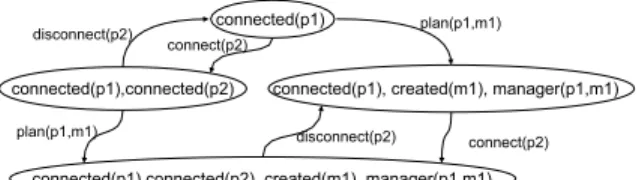
We call such a transition system a Use Case Transition Sys-tem (UCTS). The states of the transition sysSys-tem represent the state of the system (in terms of predicates) at differ-ent stages of execution. Each transition is labeled with an instantiated use case, and represents the execution of this instantiated use case. A path in the UCTS is thus a valid sequence of use cases. A partial UCTS obtained for the vir-tual meeting example (with 2 participantsp1andp2and 1 meetingm1) is given on figure 5.
Due to its finite set of states (itself due to the finite num-ber of combinations of instantiated predicates), the UCTS is itself finite. Its maximal size in the worst case is2
np Q n v i=1 vi states, wheren
vis the number of types used, v
iis the num-ber of possible values for each typei, andn
pis the number of predicates. This maximal size is reached when all the predicates have parameters of each possible type, and when all the possible states are reachable from the initial state. In practice, this maximal size is never reached. For the virtual meeting with 3 participants and one meeting, the UCTS has 1616 states.
Figure 5. Extract of the UCTS for the virtual meeting
The UCTS is an answer for Binder’s second question: a test objective has to be a path in the UCTS to be a correct sequence of use cases. The UCTS represents all the valid sequences of use cases. In a way, the contract system it-self is already an answer since it contains the information to build the UCTS, but the UCTS makes the ordering explicit.
Building algorithm
The algorithm that builds such a UCTS from a set of con-tracts is given in Algorithm 1. The initial state is built from the initial true predicates. Then the algorithm tries to suc-cessively apply each instantiated use case, as a puzzle game. Applying an instantiated use case is possible when its pre-condition is true w.r.t the set of true instantiated predicates contained in the current state’s label. Applying an instanti-ated use case leads to create an edge from the current state to the state representing the system after that the postcondi-tion is applied. The algorithm stops when all the reachable states have been explored.
To obtain the instantiated use cases from the formal de-scription of the use cases, the possible instances (values) of each type are given, that corresponds to the enumeration of all the types of the system. In practice, we give the building algorithm all the instances it has to deal with, in the form of a declaration. As an example, to deal with 3 participants and 1 meeting, we declared:
p1, p2, p3:PARTICIPANT
m1: MEETING
3.2
Test case generation w.r.t coverage criterion
A UCTS is a compact representation of all the possible orderings of the use cases. From an UCTS, we aim at gen-erating test objectives w.r.t a given UCTS covering crite-rion. We define in this sub-section fourstructural criteria
to cover an UCTS and then onesemantical criterion. A test objective is defined here as a finite sequence of in-stantiated use cases. It has to be noticed that in most cases, a test objective cannot be directly used on an implementa-tion, a test case generator has to be used to go from test objectives to test cases (see section 5.1).
Algorithm 1Algorithm producing the UCTS algorithmbuildUCTS
paraminitState: STATE ; useCases : SET[ACTION] var result : UCTS to_visit : STACK[STATE] currentState : STATE newState : STATE init result.initialState initState to_visit.push(initState) body while (to_visit6=) do currentState to_visit.pop 8 uc 2useCases | cur-rentState )uc.pre do
newState apply(currentState, uc)
if newState 2=result
then
result.Q result.Q {newState}
to_visit.push(newState) fi
result.,! result.,!
{(cur-rentState,uc,newState)} done
done end
return result
A set of test objectives is said to be consistent with an UCTS iff each test objective exercises a path of the UCTS. A path in the UCTS is here defined as the classical notion of path in a graph, the first vertex corresponding to the initial state.
All Edges criterion: A set of test objectivesTOssatisfies theall edgescoverage criterion for a use case transition systemuctsiff each edge involved inuctsis exercised by at least one test objective fromTOs,more formally iff8t2,!9to
i
2TOst:action2to i
All Vertices criterion: A set of test objective TOs satis-fies the all verticescoverage criterion for a use case transition system ucts iff each vertex v involved in
ucts is exercised by at least one test objective from
TOs (i.e. when a transition leading to or incom-ing from v is exercised), more formally iff 8q 2 Q9to
i
2 TOs9iuc 2 to i
9t 2,!t:action = iuc^(t:origin=q_t:dest=q)
All Instantiated Use Cases criterion: A set of test objec-tivesTOssatisfies theall instantiated use cases cov-erage criterion for a use case transition systemuctsiff each instantiated use case of the system is exercised by at least one test objective fromTOs, more formally iff8iuc2 IUC 9to
i 2 TOs9iuc to 2 to i 9t 2,! iuc =iuc to ^iuc to
=t:action,IUC being the set of all the instantiated use cases of the system.
All Vertices And All Instantiated Use cases criterion:
(AV-AIUC) A set of test objectivesTOs satisfies the
all instantiated use casescoverage criterion for a use case transition system ucts iff each instantiated use case of the system and each vertex involved inuctsare exercised by at least one test objective fromTOs.
Theall edges andall verticescriteria are classical criteria used for automata or graph coverage. Theall edgescriterion subsumes all the other criteria: having each edge exercised at least once obviously implies that each instantiated use case is exercised, since edges are labeled with instantiated use cases; it also implies that the vertices are exercised.
In addition, we propose asemanticalcriterion, which is not directly based on the UCTS but rather on the contracts system. This criterion is similar (but not identical) to thefull predicate coverageproposed in [12] in the context of test criteria for state-based functional specification. The philos-ophy of the criterion All Precondition Termsis to guaran-tee that all the possible ways to apply a use case are exer-cised. A use case can be applied iff its precondition is true; this precondition being a logical expression on predicates, there are several valuations of the predicates which makes it true (as an example, if a precondition isaorb, three valua-tions makes it true:(ab)(anotb)(notab)). The crite-rionAll Precondition Termswill find sequences of use cases such that each use case is applied with all the reachable val-uations of the expression :(precondition=true).
All Precondition Terms criterion: A set of test objectives
TOssatisfies the All Precondition termscriterion for a contracts system iff each use case is exercised in as many different ways as there are predicates combina-tions to make its precondition true. More formally, for eachuc 2ensuc, letE be the set of valuations mak-ing uc:pretrue. Then, 8uc 2 set
uc
8(e 2 Ej9q 2 Qq:label ) e)9t 2,!t:action 2 uc:set
iuc ^ t:origin:label)e.
Each of the proposed criterion has a corresponding algo-rithm (implemented in our prototype tool), that produces a set of consistent test objectives satisfying the criterion. All those algorithms are based on a breadth-first search in the UCTS, from its initial state. Such a technique ensures that the obtained sets of test objectives are consistent with the considered UCTS. The result of our algorithms depends on the order the nodes are visited, they thus contain some indeterminism, even if our implementation is totally deter-ministic. The choice of a breadth-first search is made in order to obtain small test objectives: small tests are more meaningful and humanely understandable than large ones.
Using a breadth-first search algorithm ensures that the size of the computed paths is minimal, but does not ensure that the number of paths found is minimimal.
Algorithm 2Algorithm producing the set of test objectives satisfying theall verticescriterion
algorithmbuildTestObjectives_With_criterion_All_vertices
paramucts : UCTS var result : LIST[LIST[IUC]] built_paths : LIST[LIST[EDGES]] init ucts.resetVisitingMarks; ucts.initState.set(visited) 8 t 2ucts.initState.getOutgoingTransitions() do
List l=new List;l.add(t); built_paths.add(l); t.destination.set(visited); done body while (ucts.nodes_to_visit6=) do
var new_built_paths : LIST[LIST[EDGES]];
8 p 2built_paths do if (p.getLastElement. getOutgoingTransitions()=) then result.add(p.dumpIUC()) else 8 t 2p.getLastElement. getOutgoingTransitions() do if t.destination.is_visited then result.add(p.dumpIUC()) else temp_p:LIST[EDGES]; temp_pclone(p);temp_p.addLast(t); new_built_paths.add(temp_p); t.destination.set(visited); fi done fi done built_paths=new_built_paths done end return result
Algorithm 2 provides the algorithm allowing to generate the set of test objectives consistent with theall vertices cri-terion. The algorithms for the 4 structural criteria are very similar, they differ essentially from the marking process and the stop condition. For the all edges criterion, the edges are marked (instead of the vertices), and the algorithm stops when all the transitions has been visited. For theall IUC cri-terion, the IUC are marked, and the algorithm stops when all the existing IUC have been marked. Algorithm 3 provides the algorithm for the semantical criterion:All Precondition
Algorithm 3Algorithm producing the set of test objectives satisfying theall precondition termscriterion
algorithmbuildTestObjectives_with_APT_criterion
paramucts : UCTS, set_uc : LIST[USECASE] body
8 uc 2set_uc
do
var set_b : LIST[BoolExpr]
set_b getAllTrueValuations(uc.pre) 8 e 2set_b do if (getPath(e,ucts).dumpIUC())6=Ø then result.add(getPath(e,ucts).dumpIUC) fi done done return result end . function getAllTrueValuations param b :BoolExpr return LIST[BoolExpr]
// return all the valuations making b true, //under the form of boolean expressions
.
function getPath
param b:BoolExpr, ucts:UCTS
return LIST[EDGES] Ø
// return the first ucts path found leading //to a state where b is true,
//or an empty list if such a path can-not be found
Terms. In this algorithm, all the valuations making the pre-condition true are computed, and then paths in the UCTS are found to reach states that verify those constraints.
4
Robustness testing
In the previous section, we have proposed a structure – the UCTS– describing all the possible orderings of instan-tiated use cases, and criteria to cover it with test objectives. For each criterion, we provided an algorithm to compute a set of test objectives satisfying it. Those functional tests ob-jectives aim at testing whether the functional requirements expressed in the use cases are satisfied, but do not verify that unexpected behaviors occur when contracts are violated. In other words, this method and its associated criteria does not provide robustness tests. This section explains how it is possible to generate robustness tests from the requirements with contracts.
In order to be able to generate robustness tests from use cases enhanced with contracts, the contracts must be de-tailed enough so that all the unspecified behaviors are in-correct. If so, the UCTS built from the enhanced use cases will be used as an oracle for the robustness. To improve the contracts, we propose to use a requirement simulator, which allows the requirement analyst to see step by step which use
cases are applicable, and then to determine if their contracts are sufficient. This simulator interactively computes valid sequences of instantiated use cases: all the choices are made by the simulator’s user, by selecting an instantiated use case in a list of all the applicable instantiated use cases.
Robustness test generation
As soon as the requirements are precise enough, the gen-erated UCTS can be used as an oracle for robustness tests. The principle is to generate paths that lead to an invalid ap-plication of a use case. The idea is thus to correctly exercise the system and then to make a non specified action. The execution of such a robustness test must lead to a failure (in our example, the receipt of an error message). If not, a robustness weakness has been detected. The goal is thus to test the robustness/defensive code of the system. The difficulty is to propose an adequate criterion. The UCTS plus the contracts provide all the information we need for that purpose. The criterion we use to generate robustness paths with the UCTS is quite similar to theAll Precondition Terms one: for each use case, it looks for all the shortest paths leading to each of the possible valuations that violate its precondition.
Robustness criterion : A set of test objectivesTOs satis-fies the robustness criterion for a contracts system iff each use case is exercised in as many different ways as there are predicates combinations to make its precon-dition false. More formally, for eachuc2 ens
uc, let Ebe the set of valuations makinguc:prefalse. Then, 8uc2 set
uc
8(e 2Ej9q 2Qq:label )e)9t2,! t:action2uc:set
iuc
^t:origin:label)e.
The robustness tests will test the defensive code of the ap-plication, which is not tested with the functional tests previ-ously generated. Joining the two sets of tests, not only will we test that the application does what it should (according to the requirements) but also that it does not what it should not.
5
Experimental validation: test cases
gener-ation and criteria comparison
This section offers an experimental validation of the pro-posed approach. We first detail the experimental process we used to bridge the gap between the test objectives and the test cases runnable on an implementation of our vir-tual meeting. Then, we study and compare the efficiency of the generated tests (both the functional and robustness ones) w.r.t a code-coverage measure. Finally, we compare our approach (use cases enhanced with contracts) with an approach using activity diagrams (ADs) as a basis to gener-ate test objectives.
5.1
From test objectives to test cases
As explained in Section 3, our test generation from re-quirements provides the tester with test objectives, i.e. se-quences of instantiated use cases. A test case generator has to be used in order to produce concrete test cases from those test objectives.
The test case generator is based on the use of scenarios documenting use cases. Indeed, we assume that sequence diagrams are attached to each use case. The idea is, for each test objective, to “substitute” the use case by one of its scenarios. In our example, there is only one scenario per use case, which corresponds to a single command of the system. Then we obtain the test cases using a template associated to each use case giving the syntactic requirements of the implementation. Other existing test cases generation can be used such as TGV[13] or AGATHA[9].
5.2
Study of the generated test efficiency
System structure. For the experimental validation, we used a Java implementation of the virtual meeting. This imple-mentation is made of about 35 classes and 150 methods. We analyzed our implementation code and partitioned it into four categories as shown in figure 6. Around 9% of the code is dead code. Nevertheless, this code is relevant: it consists of pertinent but unused accessors, which could be used in future evolutions of the system. Functional testing cannot deal with this code: it has to be tested during the unit testing. For the following study, we removed those 9% of dead code to focus on the efficiency of our tests on reach-able code. Around 26% of the code is robustness code: ro-bustness w.r.t. the specification which asserts that only the required functions are present, and robustness w.r.t. the en-vironment which asserts that the inputs coming from the environment are correct.
A lesson learnt during this study is that our testing ap-proach does not replace integration or unit testing stages, that allow specific aspects that are not described at very high level to be covered.
Results for functional testing.For criteria comparison, we generated the test cases with each of the criteria, and mea-sured the percentage of covered code (using the tool JTra-cor [7]). Statistics on the test cases generated for the virtual meeting system are given in table 1. For all the criteria, the average size of each test case (length of a use case se-quence) varies from 5 to 11 instantiated use cases, and so the test cases are easy to interpret.
The results of the code coverage measures are given in figure 7, in the form of a percentage of covered by func-tional test cases. Except for theAll verticescriterion, a 70% code coverage is reached by all the criteria, and combined with robustness criterion, 80% of the code is covered. The
Figure 6. Code analysis
Criterion # generated test
objectives average size of the tests All edges 13841 11 All vertices 769 10 All instantiated UC 50 5 AV-AIUC 819 10
All precondition terms 15 5
Table 1. Statistics on generated tests
code coverage of theAll verticescriterion is weak since op-timally covering all vertices of the graph does not even en-sure that all the use cases are used once: the use cases that do not modify the system state are not covered (since they appear as loops on a single vertex of the UCTS).
IfAll vertices,AV-AIUC,All instantiated UC,andAll pre-condition term criteria are equivalent for code coverage, their respective efficiency is not equal. In figure 8 , we pro-pose to estimate their efficiency, in terms of a ratio between the covered statements and the test cases. Intuitively, it cor-responds to the relative contribution a test case makes to code coverage. It clearly appears that each test case gener-ated with the criteriaAll edges,All verticesandAV-AIUChas a low efficiency in average. This is due to the fact that the sets of test cases generated with those criteria are not more efficient (in terms of code coverage) but only larger than the sets of test cases generated with theAll instantiated UC
andAll precondition termscriterion. Indeed, theAll edges
criterion generates for example 13841 test cases (see Table 1).
As a conclusion to this study, theAll instantiated UCand
All precondition termscriteria appear as the most efficient criteria in terms of code coverage. Those criteria thus an-swer the third Binder’s question: functional test is achieved when all the test cases generated with one of the criteria have succeeded.
Robustness tests. To estimate the quality of the robustness
Code covered by functional test cases Code covered by robustness test cases
50 55 60 65 70 75 80 85
All edges All vertices All inst. UC All inst. UC and All edges All precondition terms % covered code
Code covered by functional test cases Code covered by robustness test cases
50 55 60 65 70 75 80 85
All edges All vertices All inst. UC All inst. UC and All edges All precondition terms % covered code
Figure 7. A comparison of criterion w.r.t. code coverage 0 4 8 12 16 20
All edges All vertices All inst. UC All inst. UC and All edges All precondition terms # covered satements # test cases 0 4 8 12 16 20
All edges All vertices All inst. UC All inst. UC and All edges All precondition terms # covered satements # test cases
Figure 8. A comparison of criterion w.r.t test cases efficiency
criterion presented in Section 4, we generated the 62 test cases with the robustness criterion. Since the code cover-age of those robustness tests is not meaningful on its own, we computed the coverage of the union of sets of functional test cases (previously generated) with those 62 test cases. The obtained results are presented in Figure 7, as a percent-age of code covered by the robustness test cases. As men-tioned above, the robustness code can be divided into two categories, the robustness w.r.t. the environment, and the ro-bustness w.r.t. the requirements. Since our roro-bustness tests come from functional requirements, they cannot cover all the robustness code but they cover 100% of the robustness code w.r.t. the requirements. The uncovered code concerns syntactical verifications of the inputs, and treatments of net-work exceptions (these aspects are specific to the distributed platform).
and a robustness one. In the next section, we compare in terms of test efficiency our approach (using contracts) with another one using activity diagrams to express the use cases dependencies.
5.3
Activity diagrams vs contracts
Since several methods propose to use activity diagrams to express sequential dependencies of the use cases, we compare our contract approach with an approach using ac-tivity diagrams. Our acac-tivity diagram is divided into swim-lanes, one per actor in the system and seeks to express the dependencies between use cases, similarly to what we ex-press with contracts. Precedence constraints are exex-pressed thanks to ControlFlows andJoinNodes. Choices are rep-resented byDecisionNodesand correspond to the different calls users can perform. Such an activity diagram is given on figure 9.
Moderator Participant
Manager
Connect Connect Connect
Plan Consult Open Enter Enter Ask HandOver Speak Leave Close Over Leave Disconnect Disconnect Disconnect
Figure 9. A simplified activity diagram for the virtual meeting system
To compare the two approaches in terms of test effi-ciency, we translated the activity diagrams into a contracts system. The algorithm is available in [1]. Then we com-pared the tests obtained with the original contracts system and with the one stemming from the activity diagram. In the following, we first explain the translation from activity diagrams to a contracts systems, then we discuss which lan-guage is most adapted to express dependency between the
use cases, and finally we compare the obtained test cases in terms of code coverage.
A qualitative comparison. So far, we had expressed the virtual meeting requirements in both AD and contract system formalism. In the following, we compare those two approaches in terms of expressiveness and easiness of use.
On the one hand, the activity diagram is much more dif-ficult to build, since the use cases interactions have to be thought globally. On the opposite, writing contracts is much easier, since we only have to think in terms of the require-ments a use case has in order to be applicable, and in terms of the consequences the execution of a use case has on the system.
On the other hand, the activity diagrams being a graph-ical language, they are supposed to be more easily under-standable. But as soon as the activity diagrams have to com-pletely describe the system behavior, they quickly become very difficult to read, due to a huge number of control nodes introduced to handle loops and interactions between actors. Due to this complexity, we studied two activity diagrams for the virtual meeting system. The first one (AD1) is simple and without loops (AD1 is given on Figure 9). The second one (AD2) was built by completing the first one to express all the system behaviors. Yet, AD2 is not complete since all interactions between actors are not possible to express. For example, it is not possible to express that when the moder-ator closes a meeting, then all the participants are ejected from the meeting.
To conclude, ADs are well-suitable for very simple sys-tems (or to document partial behaviors), but for complete and realistic systems, the contracts approach is more ade-quate regarding both complexity and expressiveness.
Comparison of tests efficiency. To compare the efficiency of the generated tests, we first studied the inclusion rela-tion existing between them. As shown in Table 2, 80 % of the tests generated from AD1 (resp. AD2) are included in the UCTS built from the contracts system. Studying the remaining 20% of tests showed that those tests were not cor-rect. This means that the test generation from an AD may lead to generate sequences of use cases that are expected to be valid, while they contradict the requirements. Those in-correct test sequences come from the fact that, as previously said, some interactions were not possible to express with an AD.
Expressing use cases dependencies with an AD thus leads to generate tests accepting (and requiring) incorrect behaviors. That is why we consider the AD as a wrong ba-sis to generate test objectives.
To estimate the quality of the test cases generated using activity diagrams as a way to express dependency of use cases, we compare them with the test cases obtained using the contracts system. To perform a meaningful compari-son, we removed the incorrect test cases generated from the
AD1 AD2 Number of test objectives
with the all edges criterion 346 436
Inclusion of the generated
paths in the original UCTS 278/346 (80%) 350/436 (80%)
Table 2. Inclusion of tests generated from ac-tivity diagrams in the UCTS of the contracts system
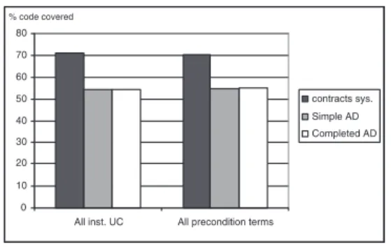
ADs. The results of this comparison are given in Figure 10.
0 10 20 30 40 50 60 70 80
All inst. UC All precondition terms
contracts sys. Simple AD Completed AD % code covered 0 10 20 30 40 50 60 70 80
All inst. UC All precondition terms
contracts sys. Simple AD Completed AD
% code covered
Figure 10. Compared test coverage of test cases generated from activity diagrams and contracts system
Due to the low expressiveness of ADs, their generated test cases lead to a poor code coverage, as it clearly appears in Figure 10. An interesting point is that completing the sim-ple AD did not significantly improve the efficiency of the generated test cases.
To conclude, expressing requirements dependencies with contracts is more adapted to automated test generation than using ADs since:
contracts are more expressive than AD and thus lead to a more complete test coverage,
for the same level of specification, the relative effort to write contracts is less important than to draw an activ-ity diagram,
the ADs may lead to generate a significant amount of invalid test cases.
6
Related work
The main contribution for system testing from use cases can be found in [3, 4]. The authors propose to express the
sequential constraints of the use cases with an extended ac-tivity diagram, with new stereotypes for expressing itera-tion. One activity diagram is provided per actor, and the use cases are grouped into swimlanes depending on the respon-sibilities they have w.r.t the main objects of the system. The activity diagram is then transformed into a weighted graph, from which regular expressions are exhaustively extracted. The regular expressions correspond to use case sequences. Then, all use cases are supposed to be documented with se-quence diagrams. Those ones are also transformed into reg-ular expressions. Finally, in each sequence of use cases, the use cases are replaced with their scenarios’s regular expres-sion. In this way, test cases are obtained. However, several limitations appear. First, the test criteria is based on the coverage of the regular expressions obtained by the projec-tion from the activity diagram. This criterion leads to a very high number of test cases: we believe that test criteria have to be found, leading to a more realistic number of test cases. Second, as outlined in 5.3, the activity diagram is either a very incomplete basis to generate significant test sequences (so all functions are not covered) or very complex to define (with the risk of specifying infeasible use-case sequences). Moreover, not all the interactions between actors are taken into account.
Other approaches rely on use cases and scenarios to gen-erate system tests. In [16] a method is detailed in order to systematically derive test cases for system testing. In [8], a complete approach is proposed to generate system-level test cases from an accurate description of the use cases of a system. The use cases description includes pre and post conditions in natural language, and scenarios, also in nat-ural languages. Then each use case is transformed into a state machine. The test objective is described in the form of a certain state to reach. Then the problem to find a test se-quence to achieve the test objective is modeled (and solved) as a planning problem. Coverage criteria are given to cover the state machines. The limitations of this method is that it does not take into account the sequential dependencies ex-isting between the use cases, independently from the rela-tionships proposed by the UML. Moreover, the transforma-tion from a use case descriptransforma-tion to a state machine is done manually.
Concerning requirements-based testing, a good overview of the state of the art is given in [15]. The conclusion of this state of the art is that automated test case generation is mainly done from formal specification, and so is far too expensive for a practical use. Moreover it does not lead to good coverage. The authors suggest then to focus on methods guiding the testers into a systematic test approach. The test generation from UML artifacts is now the object of a large number of works. In particular, [11] proposes an approach to generate tests from UML state machines, w.r.t. efficient test coverage. This technique is well suited for unit
testing, but not for system testing (or for system of small size), since a system can hardly be entirely described with a unique state machine (and if it is possible, its size would be too large to use it).
Generating tests from contracts has been done in [5] for unit testing. The principle was to use contracts written in JML to generate a test oracle. Nevertheless only the oracle is generated, and not the entry data in this method.
7
Conclusion and future work
This paper describes a requirement-based testing tech-nique that leverages use-cases to generate functional test objectives. These test objectives may be easily derived as test cases for sequential systems such as the one stud-ied in the paper. This technique is associated with a light declarative formalism to express the mutual dependencies between the use cases, in terms of pre/post conditions (kind of “contracts”). From these enhanced requirements, a la-beled transition system is built to capture all the possible valid sequences of use-cases from an initial configuration. Several structural coverage criteria are proposed and com-pared. Two other criteria (semantical coverage) are also in-troduced and their efficiency compared with the others. The first aims at covering, with short sequences of use-cases, all the semantically different ways to exercise a use case. The second is similar except that at the end of a valid sequence of use-cases, it violates one use case precondition, in ev-ery semantically different possible ways, in order to exer-cise the robustness capability of the system under test. One structural criterion (all instantiated use cases) and the two semantic criteria (all preconditions terms androbustness) have clearly been found more efficient than the others.
Concerning the efficiency of such requirement-based testing approach, the main lesson is probably that it does not replace integration or unit testing, that allow specific aspects to be covered, that are not described at very high level. The promising result is that, for the strict coverage of functional and robustness code, results are good since all the code that could be covered has been covered.
Unlike previous testing techniques that order use-cases to generate tests (e.g. using activity diagrams), this ap-proach only generates valid use-case sequences, as shown in a comparison with tests generated from an activity dia-gram (20 % of the sequences of use-cases are invalid on the studied example).
Future work are two-fold : first connecting the prototype to a UML CASE tool, using specific more adequate (less ad hoc) test case generator, and validating the approach on other case studies. Second, we would like to study the func-tional variants for product-line software and also the flexi-bility of the approach to deal with the fact that requirements are frequently modified in an OO life-cycle.
References
[1] technical and experimental material.
http://www.irisa.fr/triskell/results/ISSRE03/.
[2] R. Binder. Testing object-oriented systems, chapter 8. Addison-Wesley, 2000.
[3] L. Briand and Y. Labiche. A UML-based approach to system testing. Technical report, Carleton University, 2001. [4] L. Briand and Y. Labiche. A uml-based approach to system
testing. Journal of Software and Systems Modeling, pages 10–42, 2002.
[5] Y. Cheon and G. T. Leavens. A simple and practical ap-proach to unit testing: The JML and JUnit way. Technical Report 01–12, 2001.
[6] D. D’Souza and A. Wills.Objects, Component, ans Frame-works with UML, The Catalysis approach, chapter Inter-action Models: Uses cases, ACtions, and collaborations. Addison-Wesley, 1999.
[7] F. Fleurey. A framework to trace execution of java programs. url: http://franck.fleurey.free.fr/JTracor/.
[8] P. Fröhlich and J. Link. Automated test case generation from dynamic models. InProc. of the 14th European Conference on Object-Orinted Programming (ECOOP’00), 2000. [9] D. Lugato, C. Bigot, and Y. Valot. Validation and
auto-matic test generation on uml models: the AGATHA ap-proach. Electronics notes in Theorical Computer Science, 66(2), 2002.
[10] B. Meyer. Applying design by contract. Computer,
25(10):40–51, oct. 1992.
[11] J. Offutt and A. Abdurazik. Generating tests from uml spec-ifications. In Proc. of the Second International Confer-ence on Unified Modeling Language. Beyond the Standard (UML’99), 1999.
[12] J. Offutt, Y. Xiong, and S. Liu. Criteria for generating specification-based tests. InProc. of the Fifth IEEE Inter-national Conefernce on Engineering of Complex Systems, 1999.
[13] S. Pickin, C. Jard, Y. Le Traon, T. Jéron, J.-M. Jézéquel, and A. Le Guennec. System test synthesis from UML models of distributed software. InProc. of the 22nd Conference on Formal Techniques for Networked and Distributed Systems (FORTE’02), Houston, Texas, 2002.
[14] B. Regnell, P. Runeson, and C. Wohlin. Towards integration of use case modelling and usage-based testing.The Journal of Systems and Software, 50(2):117–130, 2000.
[15] J. Ryser, S. Berner, and M. Glinz. On the state of the art in requuirements-based validation and test of software. Tech-nical report, Institut für Informatik, University of Zurich, 1998.
[16] J. Ryser and M. Glinz. A scenario-based approach to val-idating and testing software systems using statecharts. In CNAM, editor,Proc. 12th International Conference on Soft-ware and Systems Engineering and their Applications, dec. 1999.
[17] K. Weidenhaupt, K. Pohl, M. Jarke, and P. Haumer. Scenario usage in system development: A report on current practice.