WiFly Command Reference, Advanced
Features & Applications User’s Guide
MODULES SUPPORTED:
RN121
RN123
RN125
RN131
RN171
RN174
RN171XV
© 2013 Roving Networks. All rights reserved. RN-WIFLYCR-UG Version 1.2r 4/30/13
Roving Networks, Inc. 102 Cooper Court Los Gatos, CA 95032 +1 (408) 395-5300 www.rovingnetworks.com
and other changes to its products, documentation and services at any time. Customers should obtain the latest relevant information before plac-ing orders and should verify that such information is current and com-plete.
Roving Networks assumes no liability for applications assistance or cus-tomer’s product design. Customers are responsible for their products and applications that use Roving Networks components. To minimize cus-tomer product risks, cuscus-tomers should provide adequate design and oper-ating safeguards.
Roving Networks products are not authorized for use in safety-critical applications (such as life support) where a failure of the Roving Networks product would reasonably be expected to cause severe personal injury or death, unless officers of the parties have executed an agreement specifi-cally governing such use.
Table of Contents
Chapter 1. Introduction
1.1 Overview ... 5
1.2 Configuration ... 6
Chapter 2. Command Reference
2.1 Command Syntax ... 9
2.2 Command Organization ... 9
2.3 Set Commands ... 10
2.4 Get Commands ... 35
2.5 Status Commands ... 37
2.6 Action Commands ... 40
2.7 File I/O Commands ... 43
Chapter 3. Advanced Features & Settings
3.1 Access Point (AP) Mode ... 45
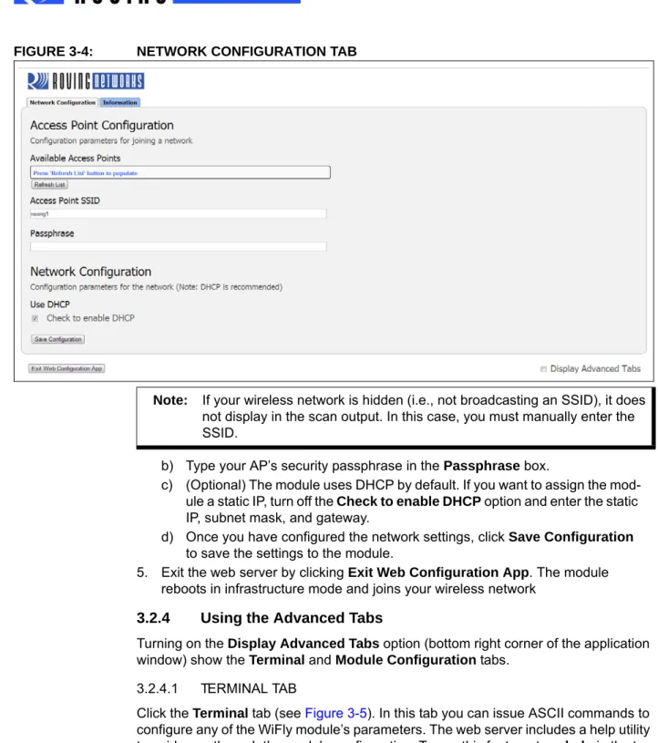
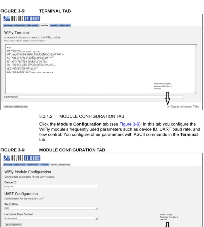
3.2 Configuration Web Server ... 49
3.3 Putting the Module to Sleep & Waking It ... 55
3.4 System & Auto-Connect Timers ... 57
3.5 Wake on Sensor Input ... 58
3.6 Wake on UART Activity ... 59
3.7 Setting Debug Print Levels ... 64
3.8 Using the Real-Time Clock Function ... 67
3.9 Time Stamping Packets ... 69
Chapter 4. Advanced Applications
4.1 Sending Data using UDP ... 71
4.2 Joining Networks & Making Connections ... 73
4.3 Making Connections ... 75
4.4 Using the HTML Client Feature ... 77
4.5 Upgrading Firmware Via FTP ... 83
4.6 FTP Client ... 86
4.7 Wi-Fi Protected Setup (WPS) ... 87
4.8 Ad hoc Networking Mode ... 89
4.9 Analog Sensor Capability ... 92
Appendix A. Default Configuration
A.1 ADHOC PARAMETERS ... 95
A.2 BROADCAST PARAMETERS ... 95
A.3 COMM PARAMETERS ... 95
A.4 DNS PARAMETERS ... 95
A.7 OPTIONAL PARAMETERS ... 96
A.8 SYSTEM PARAMETERS ... 96
A.9 TIME SERVER PARAMETERS ... 97
A.10 UART PARAMETERS ... 97
A.11 WLAN PARAMETERS ... 97
A.12 String Variable Sizes ... 97
A.13 Restoring Default Configuration Settings ... 98
Appendix B. Boot-Up Timing Values
Appendix C. Supported Access Points
Appendix D. Command Quick Reference Guide
Appendix E. Known Problems
Appendix F. Current Firmware Features & Fixes
F.1 VERSION 4.00.1 4/19/2013 ... 111
F.2 VERSION 4.0 3/27/13 ... 111
F.3 Version 2.36/2.45 9/14/2012 ... 112
F.4 Version 2.30 10/26/2011 ... 112
F.5 Version 2.27 09/08/11 ... 113
F.6 Version 2.23 04/03/2011 ... 113
F.7 Version 2.21 07/11/2010 ... 114
F.8 Version 2.20 06/14/2010 ... 114
Appendix G. Document Information
Chapter 1. Introduction
1.1
OVERVIEW
The Roving Networks WiFly radio module is a complete, standalone embedded wire-less LAN access device. The device has an on-board TCP/IP stack and applications, and in the simplest hardware configuration requires only four pins (power, TX, RX, and ground). Once you have performed the initial configuration, the device automatically accesses a Wi-Fi network and sends/receives serial data.
This user manual is applicable to standalone RN131 and RN171 modules, as well as Roving Networks products based on these modules. For example, the RN171XV device incorporates the RN171 module; therefore, all RN171 hardware features apply to the RN171XV. Although there are some differences, the RN131 and RN171 modules support the same ASCII command set. Table 1-1 compares the RN131 and RN171 module features.
Refer to the RN131 and the RN171 data sheets on the Roving Networks website at http://www.rovingnetworks.com for more details on their hardware differences and for detailed hardware specifications.
1.1.1
Features
• Fully qualified and Wi-Fi certified 2.4-GHz IEEE 802.11 b/g transceiver • FCC, CE, IC certified, and RoHS compliant
• Ultra-low power:
- Intelligent, built-in power management with programmable wakeup
- Accepts 3.3-V power supply or 2- to 3-V battery when using boost regulators - RN131: 4 uA sleep, 35 mA Rx, 210 m Tx at 18 dBm (Tx power not
configu-rable)
- RN171: 4 uA sleep, 35 mA Rx, 185 mA Tx at 12 dBm (Tx power configurable) • Antenna options:
- RN131: On-board ceramic chip antenna and U.FL connector for external antenna
- RN171: RF pad • Hardware:
- 8-Mbit flash memory and 128-Kbyte RAM, 2-Kbyte ROM, 2 Kbyte battery-backed memory
- General-purpose digital I/O pins (RN131: 10 GPIO pins, RN171: 14 GPIO pins)
TABLE 1-1: COMPARING THE RN131 & RN171
Feature RN131 RN171
Output power (PMAX) 18 dBm (fixed) 12 dBm (programmable)
Lowest power 18 dBm 0 dBm (< 100 mA Tx current)
On-board antenna Yes No
Accurate sleep timer Yes (32 kHz) No (+/- 10% error)
- 8 analog inputs (14 bits, 1.2 V)
- Real-time clock for wakeup and time stamping/data logging; auto-sleep and auto-wakeup modes
• Network support:
- Supports Soft Access Point (AP), ad hoc, and infrastructure networking modes
- Push-button WPS mode for easy network configuration - On-board TCP/IP stack
- Over the air firmware upgrade (FTP)
- Secure Wi-Fi authentication via WEP, WPA-PSK (TKIP), and WPA2-PSK (AES)
- Configuration over UART or wireless interfaces using simple ASCII com-mands
- Built in networking applications: DHCP client, DNS client, ARP, ICMP ping, FTP client, TELNET, HTTP, UDP, and TCP
1.2
CONFIGURATION
The WiFly module has two modes of operation: data mode and command mode. In data mode, the module can accept incoming connections or initiate outgoing connec-tions. To configure parameters and/or view the current configuration, you must put the module into command mode (also called configuration mode).
1.2.1
Entering Command Mode
By default, the module is in data mode after power up. Sending the escape sequence
$$$ causes the module to enter command mode. You must send $$$ together quickly
with no additional characters before or after. You must not send a carriage return (<cr>) or line feed after the $$$ to enter command mode. The module replies with CMD to
indi-cate it is in command mode. Once in command mode, you can configure the WiFly device using simple ASCII commands; each command ends with a carriage return <cr>. Most valid commands return AOK; invalid ones return an ERR description. To exit
command mode, send exit <cr>. The module responds with EXIT, indicating that it has
exited command mode and entered data mode.
You can view various parameters, such as the SSID, channel, IP address, serial port, and other settings, and configure them in command mode. You send commands to the module through the UART or via remotely via telnet. When using the UART interface, the communications settings should match the WiFly module’s stored settings. The
Note: There is a 250-ms time buffer before and after the $$$ escape sequence.
If characters are sent before or after the escape sequence within this 250-ms interval, the WiFly module treats them as data and passes them over the TCP or UDP socket, and the module will not enter command mode.
default is 9,600 baud, 8 bits, no parity, 1 stop bit, and hardware flow control disabled. You can enter command mode locally over the UART interface at any time irrespective of an active TCP connection.
When the WiFly module powers up, it attempts to auto-associate with the access point stored in its configuration settings if the auto join feature is enabled. In firmware version 4.0 and higher, the auto join feature is disabled by default. Enable it using the ASCII command set wlan join 1.
You can disable the auto-associate feature (default behavior) using the set wlan join 0
command. This command prevents the WiFly module from attempting to associate with a network that does not exist.
1.2.2
Remote Configuration Using Ad Hoc Mode
Using ad hoc mode to configure the device eliminates the need for the module to be associated with a network access point. In ad hoc mode, the module creates it’s own “on demand” network to which you can connect via your computer as you would with any other network.
To enable ad hoc mode using hardware, set GPIO9high (3.3 V) at power up. For the RN134 board, GPIO9 is on pin 1 on the jumper block (J2). For the RN174 board, GPIO9 is on the J6 connector. Upon power up with GPIO9 high, the WiFly module cre-ates an ad hoc network with the following settings:
SSID: WiFly-GSX-XX, where XX is the final two bytes of the devices MAC address
Channel: 1
DHCP: Off
IP address: 169.254.1.1 Netmask: 255.255.0.0
With the ad hoc jumper in place, these settings override any saved configuration set-tings.
From your computer, connect to the WiFly-GSX-XX network. This open network does not require a pass phrase or pass key. Currently the WiFly module only supports OPEN mode for creating ad hoc networks.
Note: Roving Networks suggests using either the TeraTerm (Windows OS) or
CoolTerm (Mac OS-X) terminal emulator program.
NOTICE
Firmware version 4.0 and higher does not support ad hoc mode (these versions sup-port soft AP mode). If ad hoc mode is required, use firmware version 2.38.3.
It may take a few minutes for Windows to assign an IP address and connect to the net-work. You can check your computer’s IP address by running the ipconfig command in
the Command Window. If connected, this command displays your computer’s IP address and netmask.
Once connected with an appropriate IP address, telnet into the WiFly module on port 2000 using the following command:
telnet 169.254.1.1 2000
The module issues the response *HELLO*. You can now enter command mode using
the escape sequence $$$ and configure the module.
In firmware versions 2.28 and higher, you can disable remote configuration, e.g., for security. To disable remote configuration, use bit 4 in the TCP mode register by issuing the command:
set ip tcp-mode 0x10
Note: The automatically assigned IP address must be on the 169.254.x.y subnet, otherwise the WiFly module will not be accessible. If your computer has both wireless and wired interface hardware, you may need to disable the wired LAN interface hardware before connecting to the ad hoc network. If the wired LAN is enabled, the computer may assign an IP address that is not on the same subnet as the WiFly module.
Chapter 2. Command Reference
Roving Networks WiFly modules support a variety of commands for configuration. This section describes these commands in detail and provides examples.
2.1
COMMAND SYNTAX
To issue commands to the module, you send a keyword followed by optional parame-ters. Commands are case sensitive, and you cannot use spaces in parameparame-ters. Use a
$ to indicate a space, e.g., MY NETWORK should be written as MY$NETWORK. Hex
input data can be uppercase or lowercase. String text data, such as the SSID, is case sensitive.
You can use shorthand for the parameters. For example, the following commands are equivalent:
• set uart baudrate 115200 • set uart b 115200
• set u b 15200
You can type numbers in decimal (e.g., 115200) or hexadecimal. To enter a number in hex, use 0x<value>. For example, the hex value FF would be entered as 0xFF.
2.2
COMMAND ORGANIZATION
There are five general command categories, as shown in Table 2-1.
When the system boots, all configuration data is loaded into RAM variables from the configuration file. The set commands only modify the RAM copy of the system
vari-ables. In general, the IP, WLAN, and UART settings require you to save and reboot before they take effect because they operate upon power up. For example, you only associate, set the channel, and obtain an IP address once at power up. Most of the other commands, e.g., COMM settings and timers, take effect immediately, allowing you to change parameters on the fly, minimizing power usage, and saving flash re-write
Note: You cannot use shorthand for command keywords. For example, s uart baudrate 115200 is illegal.
TABLE 2-1: COMMAND TYPES
Command Type Description
Set commands Set commands take effect immediately and are stored to memory when the save command
is issued.
Get commands These commands retrieve the stored information and display it. Status commands These commands display the interface status, IP status, etc.
Action commands Use these commands to perform actions such as scanning, connecting, disconnecting, etc. File I/O commands Use these commands to upgrade, load and save configuration, delete files, etc.
Note: You must save any changes you make using the save command or the
Once configuration is complete, you must save the settings to store the configuration data, otherwise it will not take effect upon reboot or reset. You can store multiple con-figurations using the save <filename> command, and you can load them using the load
<filename> command.
2.3
SET COMMANDS
These commands begin with the set keyword and include the categories shown in
Table 2-2.
2.3.1
set adhoc beacon <value>
This command sets the ad hoc beacon interval in milliseconds, where <value> is a dec-imal number from 0 to 65,436.
Default: 102
Example: set adhoc beacon 120 // Beacons are sent every 120 ms
2.3.2
set adhoc probe <value>
This command sets the ad hoc probe timeout in seconds, where <value> is the number of seconds. The probe timeout is the number of seconds the module waits for probe responses before declaring, “ADHOC is lost,” and disabling the network interface.
Default: 5
Example: set adhoc probe 80 // Sets the ad hoc probe timeout to 80 s TABLE 2-2: SET COMMANDS
Parameter Description adhoc Controls the ad hoc parameters.
broadcast Controls the broadcast hello/heartbeat UDP message.
comm Sets the communication and data transfer, timers, and matching
charac-ters.
dns Sets the DNS host and domain.
ftp Sets the FTP host address and login information. ip Specifies the IP settings.
option Supports optional and infrequently used parameters. sys Sets system settings such as sleep and wake timers. time Sets the timer server settings.
uart Specifies the serial port settings such as baud rate and parity.
wlan Sets the wireless interface settings, such as SSID, channel, and security
options.
Note: This command applies only to firmware versions supporting adhoc
net-working mode. WiFly firmware versions 4.0 and higher do not support adhoc networking mode.
Note: This command applies only to firmware versions supporting adhoc
net-working mode. WiFly firmware versions 4.0 and higher do not support adhoc networking mode.
2.3.3
set adhoc reboot <value>
This command sets the reboot timer to reboot the module periodically every <value> seconds.
Default: 0
Example: set adhoc reboot 600 // Sets the reboot timer to 600 seconds
2.3.4
set broadcast address <address>
This command sets the primary address to which the UDP hello/heartbeat message is sent, where <address> is an IP address in the form <value>.<value>.<value>.<value> with <value> being a number between 0 and 255.
Default: 255.255.255.255
Example: set broadcast address 192.168.1.50
// Sets the broadcast address to // 192.168.1.50
2.3.5
set broadcast backup <address>
This command sets the secondary address to which the UDP hello/heartbeat message is sent, where <address> is an IP address in the form
<value>.<value>.<value>.<value> with <value> being a number between 0 and 255. The secondary broadcast is also a UDP packet sent after the primary broadcast and is of 120 bytes. The secondary broadcast contains the primary broadcast (110 bytes) plus the module’s MAC address (6 bytes) and IP address (4 bytes), for a total of 120 bytes. Default: 0.0.0.0
Example: set broadcast backup 192.168.1.5
// Sets the broadcast address to // 192.168.1.5
2.3.6
set broadcast interval <mask>
This command sets the interval at which the hello/heartbeat UDP message is sent and is specified in seconds. The value is a mask that is ANDed with a free running seconds counter; if the result is all 0s, a packet is sent. For example:
• If the interval is 0x1, the module sends one packet every 2 seconds. • If the interval is 0x2. The module sends two packets every 4 seconds. • If the interval is 0x3, the module sends one packet every 4 seconds. • If the interval is 0x6, the module sends two packets every 8 seconds. • If the interval is 0x7, the module sends one packet every 8 seconds.
Note 1: <value> must be greater than 60 secs. To enable the automatic reboot feature, the reboot timer must be used in conjunction with the debug reg-ister (set system debug 0x80).
2: This command applies only to firmware versions supporting adhoc
net-working mode. WiFly firmware versions 4.0 and higher do not support adhoc networking mode.
The minimum interval value is 1 (every 2 seconds) and the maximum value is 0xff (every 256 seconds). Setting the interval value to zero disables UDP broadcast mes-sages.
Default: 7
Example: set broadcast interval 6 // Sets the heartbeat UDP message
// interval to 6 seconds
2.3.7
set broadcast port <value>
This commands sets the port to which the UDP hello/heartbeat message is sent, where <value> represents the port number.
Default: 55555
Example: set broadcast port 55555 // Sets the port to which the UDP heart
// beat is sent to 55555
2.3.8
set broadcast remote <value>
This commands sets the port to which the backup UDP hello/heartbeat message is sent, where <value> represents the port number.
Default: 0
Example: set broadcast port 4444 // Sets the port to 44444
2.3.9
set comm $ <char>
This command sets character used to enter command mode to <char>. You typically use this setting when $$$ (the default string used to enter command mode) is a
possi-ble data string. You must carefully note the new character. After you save this setting, upon every subsequent reboot the module ignores $$$ and looks for
<char><char><char> to enter command mode. Default: $
Example: set comm $ w // Sets the string to enter command mode
// to www
2.3.10
set comm close <string>
This command sets the ASCII string that is sent to the local UART when the TCP port is closed, where <string> is one or more characters up to a maximum of 32 (32 bytes). If you do not wish to use a string, use a zero (0) as the <string> parameter.
Default: *CLOS*
Example: set comm close *port closed* // Set the string to *port closed*
2.3.11
set comm open <string>
This command sets the ASCII string that is sent to the local UART when the TCP port is opened, where <string> is one or more characters up to a maximum of 32 (32 bytes). If you do not wish to use a string, use a zero (0) as the <string> parameter.
Default: *OPEN*
2.3.12
set comm remote <string>
This command sets the ASCII string that is sent to the remote TCP client when the TCP port is opened, where <string> is one or more characters up to a maximum of 32 (32 bytes). If you do not wish to use a string, use a zero (0) as the <string> parameter. Default: *HELLO*
Example: set comm remote *welcome* // Set the string to *welcome*
2.3.13
set comm idle <value>
This command sets the idle timer value, where <value> is a decimal number represent-ing the number of seconds. The idle timer value is the number of seconds durrepresent-ing which no data is transmitted or received over TCP before the connection is closed automati-cally. Setting the timer to 0 (the default) means the module never disconnects when idle.
Default: 0
Example: set comm idle 25 // Set the idle timer value to 25 s
2.3.14
set comm match <value> | <hex>
This command sets the match character, where <value> is a decimal number from 0 to 127 or a hex number from 0 to 7F. When this configuration option is set, the module sends an IP packet each time the match character appears in the data. You enter <value> either as the decimal (e.g., 13) or hex (e.g., 0xd) equivalent of the of the ASCII character. Setting the match character to 0 disables matching.
A match character is one of three available methods you can use to control TCP/IP packet forwarding. The other methods are set comm size and set comm time. For
more information refer to ““UART Receiver & RTS/CTS Hardware Flow Control” on page 60.
Default: 0
Example: set comm match 1 // Set the match character to a carriage
// return
2.3.15
set comm size <value>
This commands sets the flush size in bytes, where <value> is a decimal number from 0 to 1,420 (at 9600 baud). When this configuration option is set, the module sends an IP packet each time <value> bytes are received. Roving Networks recommends that you set this value as large as possible to maximize TCP/IP performance.
Flush size is one of three available methods you use to control TCP/IP packet forward-ing. The other methods are set comm match and set comm time. For more
informa-tion refer to “UART Receiver & RTS/CTS Hardware Flow Control” on page 60. Default: 1420
Example: set comm size 1420 // Set the flush size to 1,420 bytes
2.3.16
set comm time <value>
This command sets the flush timer, where <value> is a decimal number representing milliseconds. When this configuration option is set, the module sends an IP packet if no
The flush timer is one of three available methods you can use to control TCP/IP packet forwarding. The others are set comm match and set comm size. For more
informa-tion refer to “UART Receiver & RTS/CTS Hardware Flow Control” on page 60. Default: 5
Example: set comm time 20 // Set the flush timer to 20 ms
2.3.17
set dhcp lease <value>
This command sets the soft AP mode DHCP lease time to <value>, where <value> is the number of seconds. The module uses this value when offering the DHCP lease to each client associating with the module in soft AP mode.
Default: 86400
Example: set dhcp lease 2000 // Sets the DHCP lease to 2,000 seconds
2.3.18
set dns address <address>
This command sets the IP address of the DNS sever, where <address> is an IP address in the form <value>.<value>.<value>.<value> with <value> being a number between 0 and 255. This address is automatically set when using DHCP; you must set the DNS IP address for static IP or automatic IP modes.
Default: 0.0.0.0
Example: set dns address 169.64.1.1 // Set the DNS server address to
// 169.64.1.1
2.3.19
set dns name <string>
This command sets the name of the host for TCP/IP connections to <string>, where <string> is up to 32 characters (32 bytes).
Default: server1
Example: set dns name roving1 // Set the DNS host name to roving1
2.3.20
set dns backup <string>
This command sets the name of the backup host for TCP/IP connections to <string>, where <string> is up to 32 characters (32 bytes). The FTP client uses the backup string to download the firmware via the ftp update command.
Default: rn.microchip.com
Example: set dns backup roving2 // Set the DNS host name to roving2
2.3.21
set ftp addr <address>
This command sets the FTP server’s IP address of the FTP server, where <address> is an IP address in the form <value>.<value>.<value>.<value> with <value> being a number between 0 and 255.
Default: 0.0.0.0
2.3.22
set ftp dir <string>
This command sets the starting directory on the FTP server, where <string> is up to 32 characters. To read/write to subfolders, use the \ character. To indicate the root direc-tory, use a period.
Default: public
Example: set ftp dir demo // Set FTP server starting directory to
// demo
set ftp dir demo\test // Set FTP server starting directory to
// demo\test
set ftp dir . // Set FTP server starting directory to the
// root directory
2.3.23
set ftp filename <filename>
This command sets the name of the file that is transferred when issuing the ftp u
com-mand, where <filename> is the firmware image. If you specify any file other than the firmware image, the WiFly module downloads the file and issues the UPDATE FAIL=3
error.
Default: Firmware version 4.0 and higher:
wifly3-<version>.img (RN131), wifly7-<version>.img (RN171) Firmware lower than version 4.0:
wifly-GSX-<version>.img (RN131), wifly-EZX-<version>.img (RN171) Example: set ftp filename my_data // Sets the firmware image to be retrieved
// via FTP as my_data
2.3.24
set ftp mode <mask>
This command sets the ftp mode, where <mask> indicates active or passive mode. Default: 0x0
Example: set ftp mode 0x1 // Enables active FTP mode
2.3.25
set ftp remote <value>
This command sets the FTP server’s remote port number, where <value> is the port number.
Default: 21
Example: set ftp remote 25 // Sets the FTP server’s remote port to 25
2.3.26
set ftp time <value>
The command sets the FTP timeout value, where <value> is a decimal number that is five times the number of seconds required. The module uses this timer to close the FTP connection automatically after the specified time.
Default: 200
Example: set ftp timer 40 // Sets a 5-second timer set ftp timer 80 // Sets a 10-second timer
2.3.27
set ftp user <string>
This command sets the user name for accessing the FTP server, where <string> is up to 16 characters (16 bytes).
Default: roving
Example: set ftp user my_username // Sets the user name to my_username
2.3.28
set ftp pass <string>
This command sets the password for accessing the FTP server, where <string> is up to 16 characters (16 bytes).
Default: Pass123
Example: set ftp user my_password // Sets the user name to my_password
2.3.29
set ip address <address>
This command sets the WiFly module’s IP address, where <address> is an IP address in the form <value>.<value>.<value>.<value> with <value> being a number between 0 and 255. If DHCP is turned on, the IP address is assigned and overwritten when the module associates with an access point. IP addresses are “.” delimited.
Default: 0.0.0.0
Example: set ip a 10.20.20.1 // Sets the WiFly module’s IP address to
// 10.20.20.1
2.3.30
set ip backup <address>
This command sets a secondary host IP address, where <address> is an IP address in the form <value>.<value>.<value>.<value> with <value> being a number between 0 and 255. If the primary host IP is unreachable, the module attempts to reach the sec-ondary IP address (if set).
Default: 0.0.0.0
Example: set ip a 10.20.20.2 // Sets the WiFly module’s secondary IP
// address to 10.20.20.2
2.3.31
set ip dhcp <value>
This command enables/disables DHCP mode, where <value> is a decimal number shown in Table 2-3. If you set this parameter, the module requests and sets the IP address, gateway, netmask, and DNS server upon association with an access point. Any previously set IP information is overwritten.
TABLE 2-3: DHCP MODES
Mode Protocol
0 Turns DHCP off. The module uses its stored static IP address.
1 Turns DHCP on. The module attempts to obtain an IP address and gateway from the access point.
2 Enables automatic IP, which is generally used with ad hoc networks.
3 Turns on DHCP cache mode. The module uses a previously set IP address if the lease is not expired (or the lease survives reboot).
Using DHCP cache mode can reduce the time the module requires to wake from deep sleep, which saves power. The module checks the lease time; if it is not expired, the module uses the previous IP settings. If the lease has expired, the module attempts to associate and uses DHCP to obtain the IP settings. The DHCP cached IP address does not survive a power cycle or reset.
Default: 1
Example: set ip dhcp 0 // Turns DHCP off
2.3.32
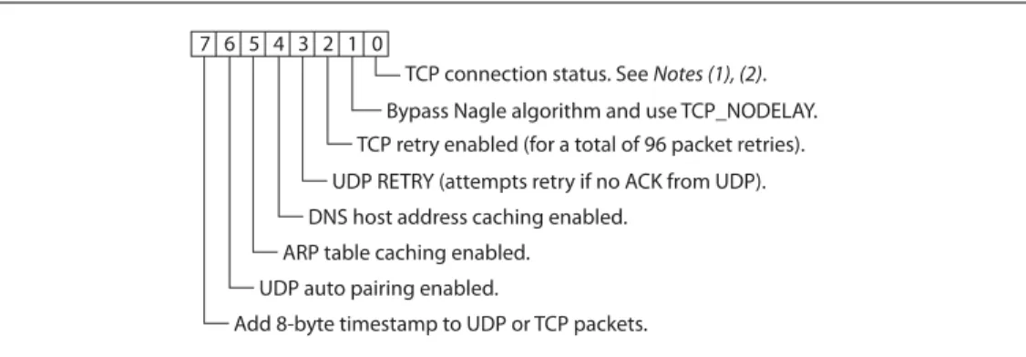
set ip flags <mask>
This commands sets the TCP/IP functions, where <mask> is a hex number referring to a bit-mapped register. See Figure 2-1.
FIGURE 2-1: SET IP FLAGS COMMAND BIT-MAPPED REGISTER
Note 1: If the module loses the link to an associated access point while a TCP
con-nection is active, the TCP concon-nection may hang or be in an inconsistent state. In some cases, the TCP connection will not recover. In firmware ver-sion 2.20 and higher, if the module regains the link to the access point within 60 seconds, the TCP connection will survive.
2: In firmware prior to version 2.20, bit 0 specified the TCP copy function.
If bit 0 is set (the default), TCP connections are kept open when the connection to the access point is lost.
If bit 0 is cleared (e.g., by sending set ip flags 0x6), if the module loses the access
point connection while TCP is connected, the connection is closed. Default: 0x7
Example: set ip flags 0x6 // Clear bit 0
2.3.33
set ip gateway <address>
This command sets the gateway IP address, where <address> is an IP address in the form <value>.<value>.<value>.<value> with <value> being a number between 0 and 255. If DHCP is turned on, the gateway IP address is assigned and overwritten when the module associates with the access point.
Default: 0.0.0.0
Example: set ip gateway 169.254.1.1 // Sets the IP gateway to 169.254.1.1
1 2 3 4 5 6 7 0
TCP connection status. See Notes (1), (2). Bypass Nagle algorithm and use TCP_NODELAY. TCP retry enabled (for a total of 96 packet retries). UDP RETRY (attempts retry if no ACK from UDP). DNS host address caching enabled.
ARP table caching enabled. UDP auto pairing enabled.
2.3.34
set ip host <address>
This command sets the remote host’s IP address, where <address> is an IP address in the form <value>.<value>.<value>.<value> with <value> being a number between 0 and 255. You use this command to make connections from the WiFly module to a TCP/ IP server with the IP address <address>.
Default: 0.0.0.0
Example: set ip host 137.57.1.1 // Sets the remote host’s IP address to
// 137.57.1.1
2.3.35
set ip localport <value>
This command sets the local port number, where <value> is a decimal number repre-senting the port.
Default: 2000
Example: set ip localport 1025 // Sets the local port to 1025
2.3.36
set ip netmask <address>
This command sets the network mask, where <address> is an IP address in the form <value>.<value>.<value>.<value> with <value> being a number between 0 and 255. If DHCP is turned on, the netmask is assigned and overwritten when the module associ-ates with the access point.
Default: 255.255.255.0
Example: set ip netmask 255.255.0.0 // Sets the netmask to 255.255.0.0
2.3.37
set ip protocol <flag>
This command sets the IP protocol, where <flag> is a bit-mapped register as shown in Figure 2-2. To be able to connect to the WiFly module over TCP/IP (for example using telnet), you must set bit 2 of the IP protocol register. For the module to accept both TCP and UDP set bits 1 and 2 (value = 3).
FIGURE 2-2: SET IP PROTOCOL COMMAND BIT-MAPPED REGISTER
Default: 2
Example: set ip protocol 18 // enables TCP and HTTP client mode
2.3.38
set ip remote <value>
This command sets the remote host port number, where <value> is a decimal number representing the port.
Default: 2000
Example: set ip remote 1025 // Sets the remote host port to 1025
1 2 3
4 0
UDP.
TCP server and client (default).
Secure mode (only receive packets form an IP address that matches the stored host IP). TCP client only.
2.3.39
set ip tcp-mode <mask>
This command controls the TCP connect timers, DNS preferences, and remote config-uration options. <mask> is a hex number referring to a bit-mapped register as shown in Figure 2-3.
FIGURE 2-3: SET IP TCP-MODE COMMAND BIT-MAPPED REGISTER
Default: 0x0
Example: set ip tcp-mode 0x4 // Forces the module to use DNS set ip tcp-mode 0x10 // Disables remote configuration
2.3.40
set opt jointmr <value>
This command sets the join timer, which is the length of time (in ms) the join function waits for the access point to complete the association process. <value> is a decimal number representing the number of ms. This timer is also used as the timeout for the WPA handshaking process.
Default: 1000
Example set opt jointmr 1050 // Sets the join timer to 1,050 ms
2.3.41
set opt format <flag>
The command sets the HTTP client/web server information, where <flag> is a bit-mapped register as shown in Figure 2-4. See “Using the HTML Client Feature” on page 77 for more details.
FIGURE 2-4: SET OPT FORMAT COMMAND BIT-MAPPED REGISTER
Default: 0x00
Example: set opt format 0x7 // Module sends sensor values Note: The TCPMODE register is available in firmware version 2.27 and higher.
1 2 3
4 0
Shorten the TCP connect timer (use with bit 1). Shorten the TCP connect timer (use with bit 0).
Forces the module to use DNS first to resolve the IP address, even if the host IP is set. Reserved.
Disables remote configuration for security purposes.
1 2 3
4 0
Automatically send an HTML header-based broadcast interval. Send users binary data (converted to ASCII hex).
Sample the GPIO and ADC pins and format to ASCII hex.
Appends &id=<value>, where <value> is the device ID string that was set using set opt device <string>. Appends the following key/value pairs to the HTTP message: &rtc=<time>, &mac=<address>,
&bss=<access point address>, &bat=<battery voltage>, &io=<GPIO in hex>, &wake=<wake reason>,
&seq=<sequence value>, where <time> is the realtime clock value in the message as a 32-bit hex value in format aabbccddeeff and <sequence value> is a rolling counter of how many web posts have been sent.
2.3.42
set opt replace <value>
This command sets the replacement character used to indicate spaces in the SSID and pass phrases string, where <value> is the ASCII value of the character. Each occur-rence of the replacement character is changed into a space. Only the WiFly command parser uses this replacement character.
For example, to change the replace character to %, use the set opt replace 0x25
com-mand (the ASCII value of % is 0x25). Default: 0x24
Example: set opt replace 0x25 // Sets the replacement character to %
2.3.43
set opt deviceid <string>
This command sets the configurable device ID, where <string> is up to 32 bytes long. You can use <string> for serial numbers, a product name, or to show other device infor-mation. The module sends the device ID as part of the UDP broadcast hello packet. You can view the device ID’s current value with the get option or show deviceid
com-mands.
Default: WiFly-GSX
Example: set opt deviceid my_wifly // Sets the device ID to my_wifly
2.3.44
set opt password <string>
This command sets the TCP connection password, where <string> is up to 32 bytes long. This setting provides minimal authentication by requiring any remote device that connects to the module to send and match the challenge <string>. When a connection is opened, the module sends the string PASS? to the remote host. The remote host
must reply with the exact characters that match the stored password in one TCP packet; otherwise, the module closes the connection. To disable the password feature, use 0 (the default).
Default: “” (no password required)
Example: set opt password my_password
// Sets the TCP connection password to // my_password
2.3.45
set opt average <value>
This command sets the number of RSSI samples used to calculate the running RSSI average for the set opt signal command.
Default: 5
Example: set opt average 10 // Sets the average to 10 RSSI readings
2.3.46
set opt signal <value>
This command allows you to configure the threshold level for the RSSI value in infra-structure mode. If the signal strength (RSSI) falls below <value> dB, the module declares AP is lost and deauthenticates itself from the network. Thereafter, the module
associates with the network based on the join policy.
This command is useful for applications in which the Wi-Fi module is in a mobile envi-ronment and frequently enters and leaves the AP’s range.
The recommended range for <value> is between 50 and 80. As <value> is lowered, the module more frequently deauthenticates itself from the AP.
Default: 0
Example: set opt signal 70 // Sets the RSSI threshold to -70 dBm. If // the RSSI average falls below -70 dBm, // the module deauthenticates itself.
2.3.47
set q sensor <mask>
This command specifies which sensor pins to sample when sending data using the UDP broadcast packet or the HTTP auto sample function, where <mask> is a bit-mapped register.
Default: 0
Example: set q sensor 0xff // Enables all sensor inputs
2.3.48
set q power <value>
This register automatically turns on the sensor power, where <value> is shown in Table 2-4. This parameter sets an 8-bit register with two 4-bit nibbles. If the top nibble is set, power is applied upon power up and removed upon power down or sleep. If the bottom nibble is set, power is applied when a sampling event occurs such as:
• UDP broadcast
• Automatic web posting of sensor data
• Power is removed immediately after sampling is complete
Default: 0
Example: set q power 0x20 // Sets power to 1.2 V automatically
// upon power up
set q power 0x02 // Sets power to 1.2 V when a
// sampling event occurs
set q power 0x40 // Sets power to 3.3 V automatically Note: This command applies in infrastructure mode only. It is not applicable in soft
AP mode.
You must enable the link monitor for this feature to work.
Note: In versions of firmware prior to 2.23, this command is named set option sensor.
TABLE 2-4: SET Q POWER COMMAND SENSOR PIN VOLTAGE SETTINGS Value Sensor Pin Voltage
0 Turn off the sensor power. 1 Ground the sensor pin.
2 1.2-V internal regulated reference.
3 VBATT input pin.
set q power 0x04 // Sets power to 3.3 V when a
// sampling event occurs
2.3.49
set sys autoconn <value>
This command sets the auto-connect timer in TCP mode, where <value> is a decimal number from 0 to 255 as shown in Table 2-5. Setting this parameter causes the module to connect to the stored remote host periodically as specified by <value>.
Default: 0
Example: set sys autoconn 5 // Module connects to host every 5 sec.
2.3.50
set sys iofunc <mask>
This command sets the I/O port alternate functions, where <mask> is a hex number referring to a bit-mapped register. The I/O function <mask> is encoded as shown in Table 2-6.
For more details see “Setting the Alternate GPIO Functions with set sys iofunc” on page 62.
Default: 0x0
Example: set sys iofunc 0x7 // Disables the WiFly board LEDs Note: To use the auto-connect timer, you must store the remote host’s IP address
and port in the WiFly module using the set ip host <address> and set ip remote <value> commands.
TABLE 2-5: AUTO-CONNECT TIMER SETTINGS Value Description
0 Disable the auto-connect timer (default).
1 Connect to the stored remote host IMMEDIATELY upon power up or when waking from sleep.
2 - 254 Connect to a stored remote host every <value> seconds.
255 Connect to a stored host IMMEDIATELY upon power up or when waking from sleep and go back to sleep IMMEDIATELY as soon as the TCP connection closes.
TABLE 2-6: GPIO PIN ALTERNATE FUNCTION BITMASK
Bit Signal Name Direction Function
0 GPIO4 Output Disable the LED function so the I/O can be used as a GPIO pin. 1 GPIO5 Output Disable the LED function so the I/O can be used as a GPIO pin. 2 GPIO6 Output Disable the LED function so the I/O can be used as a GPIO pin.
3 Unused -
-4 GPIO4 Output This pin goes high after the module has associated/authenticated and has an IP address.
5 GPIO5 Input Set this pin high to trigger a TCP connection and low to disconnect.
6 GPIO6 Output This pin goes high when the module is connected over TCP and low when discon-nected.
set sys launch_string <string>
This command sets the name of the application (indicated by <string>) that is launched when GPIO9 toggles from high to low after power up (e.g., by pressing the FN button
on evaluation kits). You use this mechanism to invoke valid applications as shown in Table 2-7.
Setting the <string> to an invalid string such as test results in the following error
mes-sage when GPIO9 is toggled:
*test not Found*
Default: web_app
Example: set sys launch_string wps_app // Sets the launch application to WPS
2.3.51
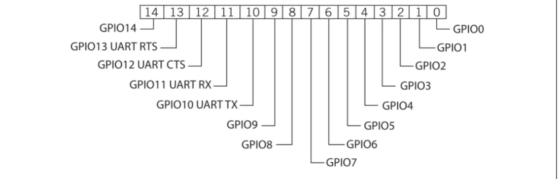
set sys mask <mask>
This command sets the I/O port direction, where <mask> is a hex number referring to a bit-mapped register. Figure 2-5 shows the bits corresponding to the GPIO pins and Table 2-8 shows the GPIO pin usage, their default state, and functionality.
FIGURE 2-5: GPIO PIN BITMASK
TABLE 2-7: VALID APPLICATION STRINGS
<string> Description
web_app Launches the configuration web server. wps_app Launches the WPS application.
Note: Do not set <string> to the configuration filename or the boot firmware image. Otherwise, the module configuration may become corrupted and the module will reboot.
Note: Disable this error message by setting the print level to zero using the set sys print 0 command.
14 13 12 11 10 9 8 7 6 5 4 3 2 1 0 GPIO0 GPIO1 GPIO2 GPIO3 GPIO4 GPIO5 GPIO6 GPIO7 GPIO14 GPIO13 UART RTS GPIO12 UART CTS GPIO11 UART RX GPIO10 UART TX GPIO9 GPIO8
For more details see “Setting GPIO Direction, Alternate Functions & Disabling LEDs” on page 60.
Default: 0x20F0 (for RN131) 0x21F0 (for RN171)
Example: set sys mask 0x0 // Sets all pins as inputs TABLE 2-8: GPIO PIN USAGE, DEFAULT STATE & FUNCTIONALITY
Bit Signal Name
RN-131 Default State
RN-171
Default State Default Function
0 GPIO0 N/A N/A
-1 GPIO1 N/A Input Unused.
2 GPIO2 N/A Input Unused.
3 GPIO3 N/A Input Unused.
4 GPIO4 Output Output Green LED.
5 GPIO5 Output Output Yellow LED.
6 GPIO6 Output Output Red LED.
7 GPIO7 Output Output Blue LED.
8 GPIO8 Input Output Unused.
9 GPIO9 Input Input Ad hoc mode and factory reset.
10 GPIO10 Output Output UART TX.
11 GPIO11 Input Input UART RX.
12 GPIO12 Input Input Throttles the transmitter if hardware flow control is enabled. Driving this pin low enables transmitter; driving this pin high dis-ables it.
13 GPIO13 Output Output This pin goes high on power up and goes low when the system is ready. If hardware flow control is enabled, this pin toggles to high to indicate the RX buffer is full.
14 GPIO14 N/A Input
-Note: On the Wi-Fi serial adapter (RN-370) and the RN-174 evaluation board, the
blue LED is connected to GPIO7. The blue LED is NOT connected to GPIO7 on the RN-134 board. It is not possible to power off the blue LED on the RN-134 board because it is connected directly to power.
Note: To set the GPIO pins as inputs or outputs instantly, use the set sys mask 0xABCD 1 command, which does not require a reboot.
2.3.52
set sys printlvl <value>
This command controls the debug print messages printed by the WiFly module on the UART, where <value> is one of the values shown in Table 2-9. Refer to “Setting Debug Print Levels” on page 64 for more information.
Default: 0x1
Example: set sys printlvl 2 // Sets the debug print messages to only
// critical network connection status
2.3.53
set sys output <mask> <mask>
This command sets the output GPIO pins high or low, where <mask> is a hex number referring to a bit-mapped register. The optional <mask> sets a subset of the pins. Default: None
Example: To toggle GPIO8, use the following commands:
set sys mask 0x21f0 // Set GPIO8 as output set sys output 0x0100 0x0100 // Drives GPIO8 high set sys output 0x0000 0x0100 // Drives GPIO8 low
2.3.54
set sys sleep <value>
This command sets the sleep timer, where <value> is a decimal number. The sleep timer is the time (in seconds) after which the module goes to sleep. This timer is dis-abled during an open TCP connection. When the TCP connection is closed, the module counts down and puts the module to sleep after <value> seconds. Setting the value to 0 disables the sleep timer, and the module will not go to sleep based on this counter.
See “System & Auto-Connect Timers” on page 57 for more details on using system tim-ers.
Default: 0
Example: set sys sleep 5 // Module sleeps 5 s after TCP
// connection closes
TABLE 2-9: DEBUG PRINT MESSAGE SETTINGS
Value Description
0 Quiet mode. Messages are not printed when the module wakes up or powers up. 1 Print all status messages.
2 Print only critical network access point connection level status, e.g., Associated! or Disconnect from
<SSID>.
4 Print the DHCP and IP address status information. After you have verified the module’s configuration, you can turn off this option so that the messages do not interfere with the data.
0x4000 Change the scan format output to an MCU friendly format.
0x10 Enables the UART heartbeat message. See “UART Heartbeat Messages” on page 67 for more details.
Note: Be sure to set the wake timer before issuing the sleep timer if you are not
2.3.55
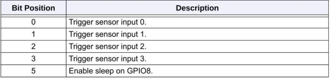
set sys trigger <flag> or <mask>
With this parameter setting, the module wakes from sleep state using the sensor input 0, 1, 2, and 3, where <flag> is a decimal number referring to a bit-mapped register as shown in Table 2-10 and <mask> is a hex number. You use either <flag> or <mask> with this parameter setting. This command sets the sensor input(s) to wake on (0 to 3). Setting <flag> to 0 disables wake on sensor inputs.
Table 2-11 describes how you can wake the module using sensor input.
Setting the trigger value to 0x20 (i.e., using <mask>) puts the module to sleep when GPIO8 is pulled high. To enable this feature, use the set sys trigger 0x20 command.
This command makes GPIO8 an interrupt pin and puts the module to sleep as soon as it is pulled high, regardless of the module’s state; the module goes to sleep even if it is associating with a network or has an open, active TCP connection.
This command is useful for when the module is failing to associate with network because it is out of range (or for any other reason), or if the module must be put to sleep quickly.
Default: 0x41
Example: set sys trigger 0x8 // Enable wake on sensor input 3
2.3.56
set sys value <mask>
This command sets the default value of the GPIO pins’ outputs upon power-up, where <mask> is a hex number representing a bit-mapped register. The GPIO pins that are configured as outputs can be driven high or low on power-up or when the module wakes from sleep. The default power-up states can be set ONLY for the GPIO pins that are set as outputs. Setting the value to 1 makes the default power-up state high; setting the value to 0 makes the default power-up state low.
TABLE 2-10: SET SYS TRIGGER COMMAND BIT-MAPPED REGISTER Bit Position Description
0 Trigger sensor input 0. 1 Trigger sensor input 1. 2 Trigger sensor input 2. 3 Trigger sensor input 3. 5 Enable sleep on GPIO8.
TABLE 2-11: SENSOR INPUT TRIGGER VALUES
Wake on Sensor Input Value Command
0 1 set sys trigger 1
1 2 set sys trigger 2
2 4 set sys trigger 4
3 8 set sys trigger 8
Note: GPIO8 must be low on power up and stay low until you want to put the
To configure GPIO pins as outputs, use the set sys mask <value> command.
Default: 0x0
Example: To configure power-up states of GPIO8 (output by default):
set sys value 0x0100 // Sets GPIO8 high upon power-up set sys value 0x0000 // Sets GPIO8 low upon power-up
2.3.57
set sys wake <value>
This command sets the automatic wake timer, where <value> is a decimal number rep-resenting the number of seconds after which the module wakes from sleep. Setting <value> to 0 disables. See “System & Auto-Connect Timers” on page 57 for more details.
Default: 0
Example: set sys wake 5 // The module wakes after 5 seconds
2.3.58
set time address <address>
This command sets the time server address, where <address> is an IP address in the form <value>.<value>.<value>.<value> with <value> being a number between 0 and 255. This command applies to SNTP servers.
Default: 64.90.182.55
Example: set time address 208.109.78.52
// Sets the time server address as // 208.109.78.52
2.3.59
set time port <value>
This command sets the time server port number, where <value> is a decimal number. 123, the default, is typically the SNTP server port.
Default: 123
Example: set time port 1052 // Sets the time server port to 1052
2.3.60
set time enable <value>
This parameter tells the module how often to fetch the time from the specified SNTP time server, where <value> is a decimal number representing minutes. The default (0) disables time fetching. If <value> is 1, the module fetches the time only once on power up. If <value> is greater than 1, the modules fetches the time every <value> minutes. Default: 0
Example: set time enable 5 // The module fetches the time every 5
// minutes
Note: GPIO pins 4, 5, and 6 are used by the firmware to blink the status LEDs. To
set the default power up states for these GPIO pins, you must first disable their use by the firmware using the set sys iofunc 0x7 command.
2.3.61
set time raw <value>
This parameter setting allows you to set the RTC raw value from the console, where <value> is a decimal number in seconds. The RTC ticks at 32,768 Hz.
Default: None
Example: set time raw 1 // Set to 1 second
2.3.62
set uart baud <value>
This command sets the UART baud rate, where <value> is 2400, 4800, 9600, 19200, 38400, 57600, 115200, 230400, 460800.
Default: 9600
Example: set uart baud 19200 // Sets the baud rate to 19,200 baud
2.3.63
set uart flow <value>
This command sets the flow control mode and parity, where <value> is a hex number. The setting is in the upper nibble of the hardware flow control setting. The default is flow control disabled with parity set to none/no parity. Figure 2-6 shows the bit-mapped register.
FIGURE 2-6: SET UART FLOW BIT-MAPPED REGISTER
Default: 0
Example: set uart flow 0x21 // Even parity with flow control set uart flow 0x20 // Even parity without flow set uart flow 0x31 // Odd parity with flow control set uart flow 0x30 // Odd parity without flow control Note: The RN134 evaluation board’s RS-232 interface cannot exceed 230,400
baud. Flow control: 0 = Disabled 1 = Enabled Parity: 00 = None 01 = Illegal 10 = Even 11 = Odd 1 2 3 4 5 6 7 0 0 0 0 0 0
Note: Once flow control is enabled, it is important to drive the CTS pin properly
(i.e., active-low enabled). If CTS is high, the module does NOT send data through the UART and further configuration in command mode is problem-atic because no response is received.
2.3.64
set uart instant <value>
This command immediately changes the baud rate, where <value> is 2400, 4800, 9600, 19200, 38400, 57600, 115200, 230400, 460800, or 921600. This command is useful when testing baud rate settings or when switching the baud rate “on the fly” while connected over TCP via telnet. Using this command does not affect configuration. The module returns the AOK response, and then the module exits command mode.
If used in local mode, the baud rate changes and the module sends AOK using the new
baud rate. If the host switches to the new baud rate immediately, the host may see the
AOK string at the new baud rate. Depending on the baud rate, it takes at least ten times
the bit rate for the module to issue the first character. Default: Not applicable
Example: set uart instant 19200 // Sets the baud rate to 19,200 baud
2.3.65
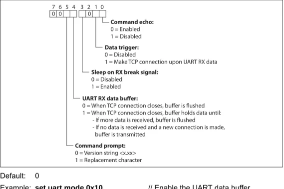
set uart mode <mask>
This command sets the UART mode register, where <mask> is a hex number masking a bit-mapped value as shown in Figure 2-7.
FIGURE 2-7: SET UART MODE COMMAND BIT-MAPPED REGISTER
Default: 0
Example: set uart mode 0x10 // Enable the UART data buffer
2.3.66
set uart raw <value>
This command sets a raw UART value, where <value> is a decimal number represent-ing the baud rate. You use this command to set non-standard baud rates. The lowest
Note: In firmware version 2.22 and lower, the module does NOT return an AOK
over telnet before exiting command mode.
Command echo:
0 = Enabled 1 = Disabled
Data trigger:
0 = Disabled
1 = Make TCP connection upon UART RX data 1 2 3 4 5 6 7 0 0 0 0
Sleep on RX break signal:
0 = Disabled 1 = Enabled
UART RX data buffer:
0 = When TCP connection closes, buffer is flushed 1 = When TCP connection closes, buffer holds data until: - If more data is received, buffer is flushed
- If no data is received and a new connection is made, buffer is transmitted
Command prompt:
0 = Version string <x.xx> 1 = Replacement character
Using non-standard raw baud rates with hardware flow control can be more useful at speeds as the microcontroller interfaced to the module may be able to better match the UART speed and get better results. Table 2-12 shows the supported raw baud rates:
Default: Not applicable
Example: set uart raw 7200 // Sets the baud rate to 7,200 baud
2.3.67
set uart tx <value>
This command disables or enables the UART’s TX pin (GPIO10), where <value> is 1 or 0. Disabling the pin (<value> = 0) sets GPIO10 as an input with a weak pull down.
Default: Not Applicable
Example: set uart tx 1 // Enable the UART’s TX pin
2.3.68
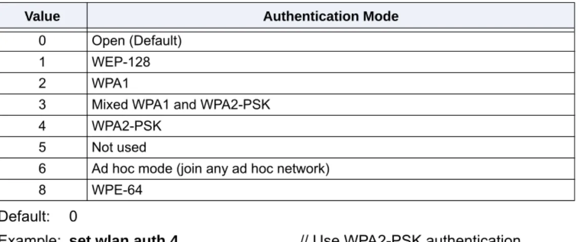
set wlan auth <value>
This command sets the authentication mode, where <value> is shown in Table 2-13. You only need to set this parameter if you are using automatic join mode 2, i.e., the set wlan join 2 command.
The firmware supports the following security modes:
• WEP-64 and WEP-128 (open mode only, NOT shared mode) • WPA2-PSK (AES only)
• WPA1-PSK (TKIP only)
• WPA-PSK mixed mode (some access points, not all are supported)
TABLE 2-12: SUPPORTED RAW BAUD RATES Raw Baud Rate Comment
458,333 This is 460,800.
500,000 Raw baud rate.
550,000 Raw baud rate.
611,111 Raw baud rate.
687,599 Raw baud rate.
785,714 Raw baud rate.
916,667 This is 921,600. 1,100,000 Raw baud rate.
Note: Firmware version 2.36/2.45 and higher supports parity with the set uart flow command
Note: During association the module interrogates the access point and
Default: 0
Example: set wlan auth 4 // Use WPA2-PSK authentication
2.3.69
set wlan channel <value> <flag>
This command sets the WLAN channel, where <value> is a decimal number from 1 to 13 representing a fixed channel and <flag> is the optional character i (meaning
imme-diate). If you set the channel to 0, the modules performs a scan using the SSID for all the channels set in the channel mask. The i flag allows you to create a temporary AP
mode setup without having to reboot or save the settings. See Example 2. Default: 0
Example 1:set wlan channel 2 // Set the WLAN channel to 2
Example 2:set wlan channel 1 i set wlan join 7 set ip address 1.2.3.4 set ip gateway 1.2.3.4
set ip netmask 255.255.255.0
set ip dhcp 4 // Use DHCP server
join <SSID> // Module goes into AP mode
2.3.70
set wlan ext_antenna <value>
This commands determines which antenna is active, where <value> is 0 (use the chip antenna) or 1 (use the U.FL connector). Only one antenna is active at a time and the module must be power cycled after changing the antenna setting.
Default: 0
Example: set wlan ext_antenna 1 // Use the U.FL antenna
TABLE 2-13: SET WLAN AUTH COMMAND AUTHENTICATION MODES Value Authentication Mode
0 Open (Default)
1 WEP-128
2 WPA1
3 Mixed WPA1 and WPA2-PSK
4 WPA2-PSK
5 Not used
6 Ad hoc mode (join any ad hoc network)
8 WPE-64
Note: This command applies only to the RN131 module; it is not applicable to the
RN171. If you send this parameter to the RN171, it issues an error mes-sage ERR: Bad Args.
2.3.71
set wlan fmon <value>
This parameter is used in soft AP mode to detect if the individual client devices are active and in range of the module.
This command sets the soft AP mode link monitor timeout threshold for the associated client device, where <value> is a decimal number representing the number of seconds of client inactivity (i.e., no data received from the client device). When this timer expires, the module deauthenticates the inactive client.
Setting this timer to a low value, e.g., 10 seconds, can result in client devices frequently deauthenticating if they do not send data before the timer expires.
To disable the fmon timer, set <value> to zero (0). Default: 3600
Example: set wlan fmon 1000 // Sets the fmon timer to 1,000 seconds
2.3.72
set wlan hide <value>
This command hides the WEP key and WPA passphrase, where <value> is 0 or 1. If this parameter is set to 0, the pass phrase or passkey is displayed. If you set this parameter to 1, the module shows ****** for these fields when displaying the WLAN
set-tings. To show the pass phrase or passkey, re-enter the key or pass phrase using the
set wlan key or set wlan passphrase command.
Default: 0
Example: set wlan hide 1 // Hide the pass phrase or passkey
2.3.73
set wlan id <string>
This command sets the EAP ID. This command is reserved for future development and is unused.
2.3.74
set wlan join <value>
This command sets the policy for automatically associating with network access points, where <value> is one of the options shown in Table 2-14. The module uses this policy on powers up, including waking up from the sleep timer.
TABLE 2-14: SET WLAN JOIN COMMAND OPTIONS
Value Policy
0 Manual. Do not try to associate with a network automatically.
1 Try to associate with the access point that matches the stored SSID, passkey, and channel. If the channel is set to 0, the module will scan for the access point. (Default)
2 Associate with ANY access point that has security matching the stored authentication mode. The module ignores the stored SSID and searches for the access point with the strongest signal. You can limit the chan-nels that are searched by setting the channel mask.
3 Reserved.
4 Create an ad hoc network using stored SSID, IP address, and netmask. You MUST set the channel. Unless another ad hoc device can act as DHCP server, set DHCP to 0 (static IP) or use automatic IP.
You can use this policy instead of the hardware jumper to create a custom ad hoc network.
7 Create a soft AP network using stored the SSID, IP address, netmask, channel, etc. This mode applies only to firmware versions supporting soft AP mode, not ad hoc mode.
Default: 0
Example: set wlan join 4 // Create an ad hoc network
2.3.75
set wlan key <value>
This command sets the WEP-64 or WEP-128 key, where <value> is EXACTLY 26 ASCII chars (13 bytes) in hex without the preceding 0x. Hex digits greater than 9 can be either upper or lower case. If you are using WPA or WPA2, enter a pass phrase with the set wlan passphrase command.
The WEP key length depends on the WEP security used (WEP-64 or WEP-128): • WEP-64 uses a 10-character key
• WEP-128 uses a 26-character key Default: 00 00 00 00 00
Example: set wlan key 112233445566778899AABBCCDD
// Sets the WEP key
2.3.76
set wlan linkmon <value>
This parameter is used in infrastructure mode to detect whether the module is associ-ated and in range of the access point.
This command sets the infrastructure mode link monitor timeout threshold, where <value> is a decimal number representing the number of failed scans before the mod-ule declares Lost-AP and deauthenticates (e.g., when the module goes out of the
access point’s range). If you set this parameter to 1 or more, the module scans once per second for the access point with which it is associated.
If the module de-authenticates itself from the access point using the link monitor, it re-attempts the association based on the join policy setting.
Roving Networks recommends setting the threshold to 30 attempts, because some access points do not always respond to probes. If you do not set this parameter, there is no way to detect that an access point is no longer present until it becomes available again (if ever).
To disable the link monitor, set <value> to zero (0). Default: 30
Example: set wlan linkmon 5 // Set the number of scan attempts to 5
2.3.77
set wlan mask <mask>
This command sets the WLAN channel mask, which is used for scanning channels with auto-join policy 1 or 2, where <mask> is a hex number (bit 0 = channel 1). Reducing the number of channels scanned for association increases battery life. This setting is used when the channel is set to 0.
Default: 0x1FFF (all channels)
2.3.78
set wlan number <value>
This command sets the WEP key number. The WEP key number must match the key number on the router or access point. You only need to set this parameter when using the WEP-64 or WEP-128 security modes. This setting is not required if you are using the WPA security mode.
Default: 0
Example: set wlan number 1 // Sets the WEP key number to 1
2.3.79
set wlan phrase <string>
This command sets the passphrase for WPA and WPA2 security modes, where <string> is 1 to 64 characters (64 bytes). The passphrase is alphanumeric, and is used with the SSID to generate a unique 32-byte pre-shared key (PSK), which is then hashed into a 256-bit number. When you change either the SSID or the passphrase, the module re-calculates and stores the PSK.
If you enter exactly 64 characters, the module assumes that the passphrase is an ASCII hex representation of the 32-byte PSK, and the value is simply stored. For passphrases that contain spaces, use the replacement character $ instead of
spaces. For example my pass word becomes my$pass$word. You can change the
replacement character using the set opt replace command. Default: rubygirl
Example: set wlan phrase my_password // Sets the phrase to my_password
2.3.80
set wlan rate <value>
This command sets the wireless data rate, where <value> is a value shown in Table 2-15. Lowering the data rate increases the effective range of the module.
Default: 12
Example: set wlan rate 13 // Set the data rate to 36 Mbits/second TABLE 2-15: SET WLAN RATE COMMAND OPTIONS
Value Wireless Data Rate (Mbits/second)
0 1 1 2 2 5.5 3 11 4 - 7 Invalid 8 6 9 9 10 12 11 18 12 24 (default) 13 36 14 48 15 54
2.3.81
set wlan ssid <string>
This command sets the SSID with which the module associates, where <string> is 1 to 32 characters (32 bytes).
Default: roving1
Example: set wlan ssid my_network // Set the SSID to my_network
2.3.82
set wlan tx <value>
This command sets the Wi-Fi transmit power, where <value> is a decimal number from 1 to 12 that corresponds to 1 to 12 dBm. The default, 0, corresponds to 12 dB, which is the maximum TX power. Setting the value to 0 or 12 sets the TX power to 12 dBm.
Default: 0
Example: set wlan tx 11 // Set the TX power to 11 dBm
2.3.83
set wlan user <string>
This command sets the EAP username. This command is reserved for future develop-ment and is unused.
2.4
GET COMMANDS
These commands begin with the keyword get and they display the module’s current
values. Except where noted, the get commands do not have any parameters.
2.4.1
get adhoc
This command displays the ad hoc settings.
Example: get adhoc // Show ad hoc settings
2.4.2
get broadcast
This command displays the broadcast UPD address, port, and interval.
Example: get broadcast // Show broadcast UDP information
2.4.3
get com
This command displays the communication settings.
Example: get com // Show communication settings
Note: <string> cannot contain spaces. If the SSID has spaces, use the $
charac-ter to indicate the space. For example, yellow brick road becomes yel-low$brick$road. When you use the get wlan command to view the SSID,
the module properly displays it as SSID=yellow brick road.
Note: This command applies only to the RN171 module; it is not applicable to the
RN131. The transmit power on the RN131 is fixed to 18 dBm. If you send this parameter to the RN131, it issues an error message ERR: Bad Args.
2.4.4
get dns
This command displays the DNS settings.
Example: get dns // Show the DNS information
2.4.5
get everything
This command displays all of the configuration settings, which is useful for debugging. Example: get everything // Show all configuration settings
2.4.6
get ftp
This