Strength design optimization of structural steel members
according to Eurocode3
Juan Francisco Carbonell-Marquez1, Luisa María Gil-Martín2, and Enrique Hernández-Montes3
Keywords: Steel Structures, Structural Optimization, Cross-Section Class, Local Buckling, Eurocode 3.
(Published in “Journal of Constructional Steel Research”, Volume 80, January 2013, Pages 213–223)
http://dx.doi.org/10.1016/j.jcsr.2012.07.019
Abstract
In order to design a steel member subjected to a bending moment and an axial load, there are an infinite number of possible solutions I- or H- steel cross-sections, the doubly-symmetric solution being just one of them. This paper presents a procedure to obtain the optimal steel cross-section from the infinite number of possible solutions. The process is based on the Reinforcement Sizing Diagrams employed in reinforced concrete strength design. The procedure looks for any type of solution regarding compact or non-compact steel sections. All aspects related to local instabilities will be taken into account, as well as special considerations in order to address the global instabilities associated with the slenderness of the steel element.
Notation
A Cross-section area employed to compute Nb,Rd At Cross-section area
Ateff Effective cross-section area for cross-sections in Class 4 A1 Top flange area
A2 Bottom flange area
E Steel elastic modulus
My External in-plane bending moment
Mb,Rd Design buckling resistance moment of a laterally unrestrained beam My,Ed External in-plane bending moment applied to the section
My,Rk Critical cross-section characteristic moment resistance about y-y axis N External axial load
Nb,Rd Design buckling resistance of a compression member NEd External axial load applied to the section
1
Ph.D. candidate. University of Granada, Campus de Fuentenueva. 18072 Granada. Spain. [email protected].
2
Associate Professor, University of Granada, Campus de Fuentenueva. 18072 Granada. Spain. [email protected].
3
Professor, University of Granada, Campus de Fuentenueva. 18072 Granada. Spain. [email protected]
NRk Critical cross-section characteristic resistance to normal force Weff,y Effective section modulus about y-y axis, for Class 4 sections Wel,y Elastic section modulus about y-y axis
Wpl,y Plastic section modulus about y-y axis
Wy Appropriate section modulus employed in the computation of Mb,Rd bfcomp Compressed flange width
bfb Bottom flange width bft Top flange width dw Web height h Centroid height
fy Specified steel yield strength
k Factor employed in the computation of the criterion to prevent the compression flange buckling in the plane of the web
lb Unbraced length of the beam-column member tfb Bottom flange thickness
tft Top flange thickness tw Web thickness
χ
Reduction factor for the relevant buckling mode in compressionLT
χ
Reduction factor for lateral-torsional buckling 1M
γ
Partial safety factor for the buildingζ
Interaction factor1.
Introduction
Typical sections for beam-column members in steel edifications are usually I- or H- rolled sections. However, in other fields of steel constructions such as civil bridges, the selected cross-sections may be welded, since the higher demands to be supported by the structure calls for larger dimensions not possible for tabulated rolled sections. Whether edification or civil construction, designers tend to proportion their structures using symmetric sections, these being just one of the multiple solutions. Nevertheless, the optimal solution may not coincide with the symmetric one and important savings in the amount of steel used could be achieved. In this respect, environmental concerns constitute an important role because savings in steel consumption may be translated into significant reductions in greenhouse gas emissions.
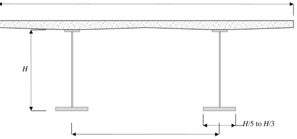
Figure 1. Conditions of the problem to be analyzed
The present work studies the optimal design of beam-column members subject to an external in-plane bending moment, My, and to an axial load, N, initially considered to be applied at the
cross-section of the element and the sign criteria for the applied external loads. Bending moment,My, acting on the strong axis of the cross-section will be considered positive when compressing the top flange of the section. The applied axial load, N, will be considered positive in tension. For the sake of simplicity, the fillets in rolled sections and throat thickness in welded sections have been ignored in the process. The different elements of the section are proportioned to provide sufficient strength and stiffness to resist the external actions and avoid premature buckling of the member. For non-compact sections, the plastic capacity will not be reached, so elastic capacity will be employed.
Figure 2. Nomenclature and sign criteria
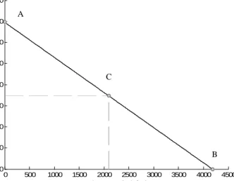
The problem studied in this work has already been solved by Gil-Martín et al. [1] for Class 1 sections. Optimization was completed by using the RSD design approaches [2-3]. This methodology, originally conceived for reinforced concrete, represents the required reinforcement area for supporting a determined external loading as a function of depth of neutral axis in the concrete section (Figure 3). When applying RSD design approaches to optimization in steel sections, minor changes need to be made. Thereby, the graphics represent the cross-section area, At, as a function of the web height,dw, and the optimal solution corresponds to the
one with the lowest value for At (Figure 4).
Figure 3. Example of RSD in a reinforced concrete section, from [4]
z 1 A 2 A ft b fb b h 2 w d ft t y M N w t 2 w d fb t y y z
The present paper explains the well-developed process that was followed to obtain the optimal solution for any pair of (My,N). The process makes it possible for the designer to choose the Class of the adopted cross-section; this is either compact or non-compact. Selecting the Class of the section is very important, for example, when designing a building for earthquake resistance according to Eurocode 8 (EC8) [5]. EC8 states that, for any given building subjected to an earthquake, the relation between its resistance and capacity for dissipating energy is related to the section classification (see Table 6.3 in EC8). Generally speaking, the more ductility needed the more compactness is required for the cross-section.
Figure 4. Example of RSD in a steel section: optimization of IPE500 under My,Ed = 288 kN m and NEd = - 483
kN with tf=16 mm and tw=10,2 mm. Point A represents the optimal solution and point B corresponds to
IPE500. Taken from [1]
In contrast to the previous case is a composite roadway or highway bridge. These kinds of bridges, which also called “twin-girder bridges”, are composed of two longitudinal steel girders connected to the concrete slab of the deck by shear connectors. Twin-girder bridges are the most economical solution when covering span lengths in the range of 30 and 100 m [6], with special suitability between 60 and 80 m [7]. Considering these span lengths, self-weight becomes an important action to be withstood. Under this load, and beyond the complexity involving a composite section, cross-sections under positive moment at mid-span regions of composite bridges are usually in Class 1 or 2, since compression is carried mainly by the concrete deck. However, on internal supports, under negative moment, sections tend to be designed in Class 3 or 4 in order to avoid the excessive amount of steel that would be needed if those compressed sections were to be in Class 1 or 2 [8].
The typical section for these kinds of bridges is shown in Figure 5. The most usual range for
H/L, being H the height of the I-section and L the covered span, is between 1/25 and 1/20 for
highway or roadway bridges and 1/15 for railway bridges [6-7][9]. For a highway bridge with a span of 600 m, H would be between 2.5 and 3.0 m. This is due to the fact that the high dimensions of the sections do not allow the designer to choose them from the standard rolled sections and a welded design is needed. For these types of girders, the algorithm developed within this work lets the designer impose any constraint related to the dimensions of a particular element of the section, in this case, web height or even related to the Class of the cross-section.
The algorithm used to optimize the sections has been implemented in a computer program and some examples are presented here. The results obtained will be analyzed in order to test the validity of the process.
Figure 5. Typical section for a twin-girder composite bridge
2.
The optimization procedure
As above explained, the optimization procedure to be presented in the current work is based on RSD methodology. This approach consists on the consideration of all the possible solutions for a design problem through a graphical representation that allows to choose the optimal one. In reinforced concrete members, usually the reinforcement area is represented in function of the neutral axis depth [2-3].
In steel construction, as was observed with reinforced concrete, an infinite number of solutions exist for the design of a steel cross-section subjected to combined loads N and M. These solutions can be presented using graphics similar to those used in the reinforced concrete RSD representation. In this case, the area of structural steel has been represented in function of the height of the web [1]. The main advantage of this procedure is that the engineering know all the possible cross-sections that resist a given combination of axial load and moment (N, M) making possible the choice, among all them, of the optimal one considering minimum weight, availability of steel shapes, simplicity on the job site, Class of the cross-section and so on.
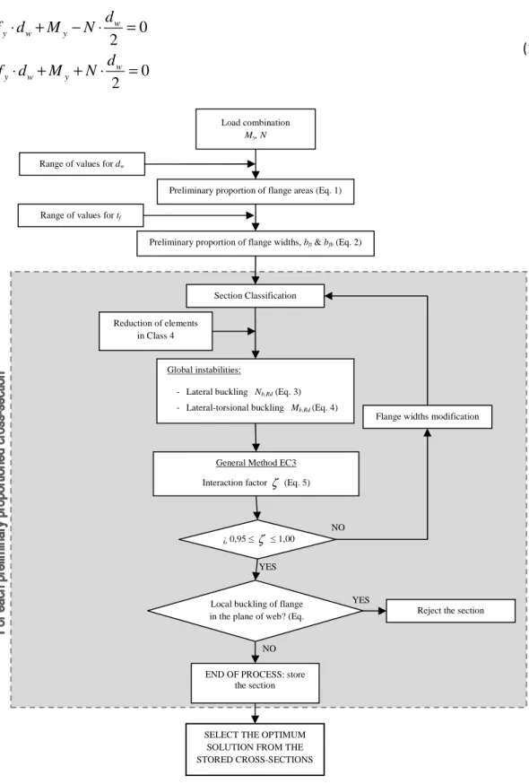
The process followed during the optimization procedure is represented in the flow chart in Figure 6.
Section initial proportioning
The first step in the process is to select a fixed value for the web thickness, tw, and a range of
values for the height of the web, dw. The range of dw is obtained accounting both shear strength
and shear buckling requirements. The flanges preliminary proportions are provided by equilibrium of forces acting on the cross-section, applying the axial load at the centroid of the web. The equilibrium is established by ignoring the web contribution and assuming that the forces carried by the top and bottom flanges act at the ends of the web and drive the flanges to the yield stress. Therefore, the sum of moments on either ends of the web results in Eq. 1:
B
H
S = 0.50 to 0.55 B
1 2 0 2 0 2 w y w y w y w y d A f d M N d A f d M N ⋅ ⋅ + − ⋅ = ⋅ ⋅ + + ⋅ = (1)
Figure 6. Flow chart explaining the entire process
Once A1 and A2 are known for each value of dw, the next step is to choose another range of
values for the flange thicknesses, tft and tfb. Therefore, for each value of tft and tfb the values of
the flange widths can be obtained from Eq. 2:
Preliminary proportion of flange areas (Eq. 1)
¿ 0,95 ≤ζ ≤ 1,00 Load combination
My, N
General Method EC3 Interaction factor ζ (Eq. 5)
Range of values for dw
Range of values for tf
Preliminary proportion of flange widths, bft & bfb (Eq. 2)
Global instabilities:
- Lateral buckling Nb,Rd (Eq. 3) - Lateral-torsional buckling Mb,Rd (Eq. 4)
-Reduction of elements in Class 4
YES
NO
Flange widths modification Section Classification
Local buckling of flange in the plane of web? (Eq.
10)
END OF PROCESS: store the section
NO
Reject the section YES
SELECT THE OPTIMUM SOLUTION FROM THE STORED CROSS-SECTIONS
1
and
2 ft fb ft fbA
A
b
b
t
t
=
=
(2)In the following, without lost of generality, the same thickness of both flanges has been considered, being, tft =tfb =tf.
Section classification
As described in Eurocode 3(EC3)[10] , the role of cross-section classification is to identify the extent to which the resistance and rotation capacity of the cross-section is limited by its local buckling resistance. The classification of a determined cross-section will depend on the slenderness, i.e. the width to thickness ratio, of the parts subject to compression.
According to EC3, there are four classes for steel sections: Class 1, which can form a plastic hinge with the rotation capacity required from plastic analysis without reduction of the resistance; Class 2, similar to class 1 but with limited rotation capacity due to local buckling; Class 3, those sections in which local buckling appears before forming a plastic hinge and are assumed to work with an elastic distribution of stresses reaching the yield strength; and Class 4, in which local buckling is reached before elastic limit [11]. This classification may also be found in other codes as AISC Steel Construction Manual [12] with other terminology and slenderness limit values. Thereby, according to AISC, Class 1 and 2 sections are called compact sections; Class 3 sections are equivalent to non-compact sections; and Class 4 sections are similar to slender sections.
The limit values for the slenderness of each component of the section are given by Tables 5.2-1 and 5.2-2, presented in section 5 of Part 1-1 in EC3. According to these standard codes, the cross-section is classified according to the highest (least favorable) class of its compression parts.
Widths of the elements of the cross-section in Class 4 have to be reduced in order to their effective dimensions according to Part 1-5 of EC3.
Global instabilities at member level
Once the class of the cross-section is determined, it is necessary to calculate the resistance of the beam-column member to lateral buckling and lateral-torsional buckling due to axial load and bending moment, respectively. Following the formulas given in EC3 [9], the design buckling resistance of a compression member should be taken as:
, 1 y b Rd M A f N
χ
γ
⋅ ⋅ = (3)where A=At for cross-sections in Classes 1, 2, or 3, and A=Ateff for cross-sections in Class 4
when subjected to uniform compression. The parameter
χ
is the reduction factor for the relevant buckling mode, computed as indicated in section 6.3.1. in Part 1-1 of EC3.On the other hand, Section 6.3.2 of EC3 [9] provides the formula to calculate the parameter
LT
χ
, i.e. the reduction factor for lateral-torsional buckling. According to this, the design buckling resistance moment of a laterally unrestrained beam should be taken as:, 1 LT y y b Rd M W f M
χ
γ
⋅ ⋅ = (4)Here, Wy is the appropriate section modulus, taken as Wpl y, for Class 1 or 2 cross-sections, ,
el y
W for Class 3 cross-sections, and Weff y, for Class 4 cross-sections when only moment about the relevant axis is applied.
When the buckling resistances of the member are calculated, the General Method for lateral and lateral torsional buckling of structural components is applied. This method, explained in Section 6.3.4 of EC3 [9], allows the verification of the resistance to the former global instabilities of single members subject to compression and mono-axial bending in the plane. The member must fulfill Eq. 5 in order to achieve stability.
, 1 , 1 1 y Ed Ed Rk M LT y Rk M M N N M
χ
⋅γ
+χ
⋅γ
≤ (5)where NRk and My Rk, are the critical cross-section characteristic resistance to normal force and moment resistance about y-y axis. In this work, applied loads NEd y My,Ed are:
(
)
, 0 y y Ed y N M =M + e +e N (6) Ed N =N (7)Being eNy the shift of the relevant centroidal axis of the cross-section due to the widths reduction
in class 4 when the member is subjected to uniform compression and e0 the distance between the
mid-height of the web –where the axial load is supposed initially applied at the gravity center of the gross-section (Figure 7), calculated as:
(
)
0 w 2 f
e = −h d +t (8)
In the above expression h is the height of the gravity centre of the cross-section.
In this work, the value for the sum presented in Eq. 5 has been called “interaction factor” and is
represented by , 1 , 1 y Ed Ed Rk M LT y Rk M M N N M χ γ χ γ
ζ
= ⋅ + ⋅ . Design adjustmentsIt is clear from the flow chart presented in Figure 6 that the proposed procedure is iterative. The dimensions of the cross-section are preliminary proportioned and classified. Afterwards, the General Method is applied to evaluate the stability of the member; because in most of the cases the preliminary cross-section will not be able to stand the applied loads without buckling, dimensions need to be modified. In this work, for each pair of values dw-tf, the width of the
flanges, bft and bfb, are adjusted until the member does not buckle, i.e.
ζ
≤1. However, in orderto gain optimal results, a lower limit has been imposed to
ζ
, so that the adjustments will be completed when 0.95≤ ≤ζ
1. The adopted process for providing a cross-section of minimumcross-sectional area, fulfilling all the stability considerations, is similar to the one followed by [1], and is explained below:
1. If
ζ
<0, 95 the section provides excess capacity. To reduce the cross-sectional area, the widths of both flanges are reduced until:0, 95≤ ≤
ζ
1 (9)2. If
ζ
>1 the section behavior is governed by instability. To provide sufficient strength, the flange areas must be increased. The approach to increase one flange or another depends on axial force and bending moment:a. If My =0 or N =0, the section is symmetric from the initial proportioning
given by Eq. 1. The area of both flanges are increased the same amount until the condition given by Eq. 9 is fulfilled.
b. If My ≠0 and N ≠0, the section from Eq. 1, the section will initially be
asymmetric. In this case, one of the flange areas is increased in order to reduce the eccentricity given by Eq. 8 until the formula given by Eq. 9 is fulfilled:
i. IfMy and Nhave an equal sign, the top flange width will increase.
ii. IfMy and Nhave a different sign, the bottom flange width will increase.
Figure 7. Values for the eccentricities e0 and eNy
Once Eq. 9 is fulfilled for certain values of dw - tft - tfc (in this example tf = tft = tfc), the
cross-section will be stored if the dimensions of the flanges in compression are sufficient to prevent local buckling in the plane of the web. According to section 8 in Part 1-5 of EC3 [13], the following criterion should be met:
h N 2 w d f t G 0 e h 2 w d f t G N Geff 0 e Ny e , ft eff b , fb eff b
2 2 3 2 w w w fcomp w y fcomp y f w d t k E t d E k b t f A f t d ⋅ ⋅ ⋅ ≤ ⇒ ≤ ⋅ ⋅ (10)
The value of k should be taken as follows:
- Plastic rotation utilized k = 0,3
- Plastic moment resistance utilized k = 0,4
- Elastic moment resistance utilized k = 0,55
All the cross-sections with their corresponding pairs of dw-tf are stored. These solutions are
sorted by cross-sectional area and the minimum is identified as the optimal solution. It is important to notice that the process may provide some solutions with the same optimal cross-sectional area. In this case, the final selected solution will be that with the minimum value of interaction factor
ζ
.Furthermore, the procedure provides an infinite number of solutions (depending on the established constraints). The optimum (i.e. minimum cross-sectional area) or the symmetric solution is just one of the possible cross-sections that may be chosen [1-3].
3.
Examples
The validity and effectiveness of the process have been tested and can be seen in the following three examples; in order to obtain minimum cross-sectional solutions for three combinations of
y
M and N with the conditions represented in Figure 1: a simple supported beam with end-fork conditions (i.e. pin supported end and free warping). The applied load combinations correspond to three points in the interaction equation (Figure 8) corresponding to a specimen made of steel Grade 235 ( fy =235N/mm2) with a cross-section HEB600 (dw =540 mm;tw=15, 50mm,
30 mm;
f
t = bft =bfb =300 mm; At =27000 mm2) and an unbraced length, lb, equals to
6,00 m. The load combinations are presented in Figure 8.
Figure 8. Interaction equation corresponding to HEB600, for fy = 235 N/mm 2 , lb = 6 m and ψ = 0 0 500 1000 1500 2000 2500 3000 3500 4000 4500 0 200 400 600 800 1000 1200 1400 1600 N (compression) (kN) M ( k N .m ) A C B
3.1.
Combination A: M
y=1391.60 kN.m –bending moment applied
on the right support of the beam-
The first combination of loads corresponds to point A in Figure 8, simple strong axis bending with a value of My =1391, 60 kN m⋅ . Figure 9 shows the obtained design solutions for different web depths, dw, with a range from 50 mm to 2000 mm with a step of 5 mm. The
adopted range of values for flange thicknesses, tf, varies from 4 mm to 40 mm, with a step of 2
mm. The HEB 600 web thickness (tw =15, 50mm) is adopted for every solution. According to
Eq. 1, if tf = tft = tfc all the obtained solutions are doubly-symmetric (i.e. bft =bfb). The results
from Eq. 1 are presented as a continuous line. Dots in Figure 9 correspond to the solutions obtained after the adjustment process for the four different Classes of the cross-section. To distinguish between each class different have been used, respectively. In Figure 9 the solution corresponding to the HEB section and the optimal ones obtained for each class using the optimization procedure have been identified. As may be observed from Figure 9, the initially proportioned dimensions for the elements of the cross-section given by Eq. 1 are subsequently modified by the adjustment process. In some cases, those dimensions have been overestimated since the contribution of the web was ignored in Eq. 1. However, many solutions have cross-sectional areas greater than initially estimated due to the fact that members turned out unstable and buckled and therefore dimensions need to be modified in order to get sufficient strength to withstand the applied loads.
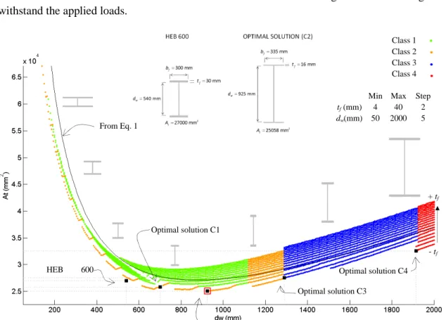
Figure 9. Cross-sectional area At of the solutions in terms of web depth dw for strong axis bending moment The solution with the lowest cross-sectional area corresponds to:
925 mm; w d = tw =15, 50mm; tf =16 mm;bft =bfb =335 mm; At =25058 mm2 HEB 600 (C1) Optimal solution C3 Class 1 Class 2 Class 3 Class 4 + tf - tf Optimal solution C1 Optimal solution C4 Optimal solution C2
Min Max Step tf (mm) 4 40 2
dw(mm) 50 2000 5
The web and top flange Classes are 1 and 2 respectively, leading to cross-section Class 2. The interaction factor is
ζ
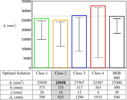
=0, 9989.Figure 10 shows the optimal solution for each Class according to EC3 and compares their cross-sectional area with the one of HEB 600. The table in Figure 10 provides the dimensions for these optimal solutions. Class 1, 2, and 3 sections reduce the flange width, bf, when increasing
web depth, dw, while in Class 4 bf increases since web is reduced for local buckling. In this case,
only compact solutions (Classes 1 and 2) provide less cross-sectional area than the standard HEB600. Figure 9 shows that a saving of 7,2 % with respect to the area of HEB600 can be obtained.
Figure 10. Comparison between the dimensions of different optimal solutions for each Class and HEB 600, for strong axis bending moment. Scale of dimensions sketches: 1/400
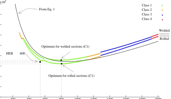
In Figure 11 the obtained results from the optimization process imposing tf =30 mm(flange thickness of HEB600) have been represented for both welded and rolled sections. This figure shows that if welded sections are considered instead of rolled sections, areas slightly larger are obtained. These differences are due to the different values of the imperfection factors corresponding to the buckling curves that are different for both welded and rolled sections. For this example no welded solution exits with a cross-sectional area under 27000 mm2 - HEB600 cross-section area- while if a rolled section is employed an area At =26098 mm2 is obtained (for dw =805 mm andbf =227 mm). 0 5000 10000 15000 20000 25000 30000 35000
Optimal Solution Class 1 Class 2 Class 3 Class 4 HEB 600 At (mm2) 25850 25058 27507 32587 27000 bf (mm) 375 335 313 363 300 tf (mm) 20 16 12 4 30 dw (mm) 700 925 1290 1915 540 At (mm2)
Figure 11 shows that the curve corresponding to rolled sections almost matches the solution corresponding to the HEB 600. These small differences are due to the fact that, as was explained earlier, in this work the fillets in rolled sections are not taken into account.
Figure 11. Cross-sectional area At of the solutions with tf = 30 mm in terms of web depth dw for strong axis
bending moment employing welded and rolled sections imperfection factors
200 400 600 800 1000 1200 1400 1600 1800 2000 1 1.5 2 2.5 3 3.5 4 4.5 5 5.5x 10 4 dw (mm) A t (m m 2) HEB 600 (C1)
Optimum for welded sections (C1) From Eq. 1
Optimum for rolled sections (C1)
Welded Rolled Class 1 Class 2 Class 3 Class 4
3.2.
Combination B: N
=
-4180.80 kN
(compression)
In this case, the steel section member is subject to a pure compression with a value of
4180,80
N= − kN . This load combination corresponds to point B in Figure 8, i.e. the buckling capacity of the considered HEB 600 member. The results for the different values of dw, with a
range from 50 mm to 800 mm with a step of 5 mm, are presented in Figure 12. Again, the HEB 600 web thickness (tw =15, 50 mm) is adopted for every solution. The adopted range of values for flange thicknesses, tf, starts at 4 mm and finishes at 40 mm, with a step of 2 mm. The
obtained optimal solution corresponds to dw =215 mm; tw =15, 50mm tf =18 mm; 492 mm;
ft fb
b =b = 2
21045 mm
t
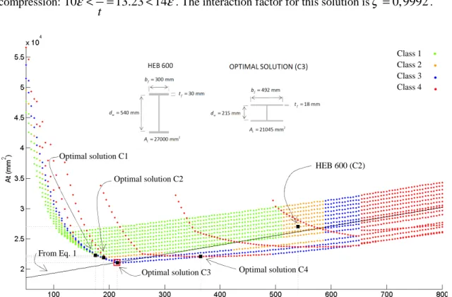
A = . This solution saves a 22,05 % of steel with respect to the HEB600. The cross-section Class is 3 due to the slenderness ratio for the flanges in
compression: 10 c 13.23 14
t
ε
< = <ε
. The interaction factor for this solution isζ
=0, 9992.Figure 12. Cross-sectional area At of the solutions in terms of web depth dw for pure compression
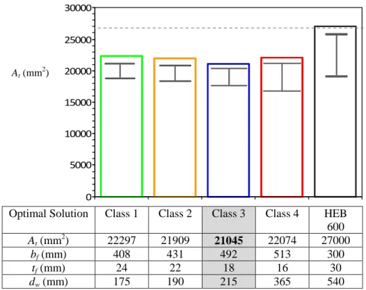
As in the former example, Figure 13 shows the optimal solution for each Class. In this particular case, all the optimal solutions have cross-sectional areas smaller that the one corresponding to the standard HEB600. As in the previous example, Eq. 1 provides symmetric solutions since, the only applied load there is now is the compressive axial load. Because the areas of the flanges are not affected by web depth, dw , the flange widths, bf, will be the same for every fixed value
of the flange thickness, tf. Figure 14 shows the evolution of the flange width, bf, as function of
the depth of the web, dw, for a fixed value of the flange thickness, tf =30 mm. The obtained
optimal solution corresponds to a web depth dw =145 mmand a flange
widthbft =bfb =357 mm. The corresponding cross-sectional area isAt =23668 mm2.
From Eq. 1
HEB 600 (C2)
Optimal solution C3 Optimal solution C4 Optimal solution C2 Optimal solution C1 Class 1 Class 2 Class 3 Class 4
Figure 13. Comparison between dimensions of different optimal solutions for each Class and HEB 600, for pure compression.
Figure 14. Flange width, bf, for the solutions of flange thickness tf = 30 mm in terms of web depth dw for pure
compression
In Figure 14 two regions appear. Region 1 corresponds to solutions where the relevant mode for lateral buckling under compression is flexural buckling (solutions are symmetric) about y-y axis. In this Region, solutions need to increase their preliminary proportioned flange width by an important amount before reaching stability, because the relevant mode is governed by the
100 200 300 400 500 600 700 800 0 100 200 300 400 500 600 700 800 900 1000 dw (mm) b f (m m ) From Eq. 1 HEB 600 Optimal solution NbRd,Z > N bRd,Y NbRd,Z < N bRd,Y 1 2 2 1 Class 1 Class 2 Class 3 Class 4 0 5000 10000 15000 20000 25000 30000
Optimal Solution Class 1 Class 2 Class 3 Class 4 HEB 600 At (mm 2 ) 22297 21909 21045 22074 27000 bf (mm) 408 431 492 513 300 tf (mm) 24 22 18 16 30 dw (mm) 175 190 215 365 540 At (mm2)
moment of inertia about y-y, which is proportional to bf: Iy ∝bf (∝ meaning being
proportional). However,
I
y∝
d
w3, resulting in much less wider solutions as dw becomes deeper.On the other hand, Region 2 corresponds to flexural buckling under z-z axis and solutions get quick stability since
I
z∝
b
f3, and solutions need to increase lightly their preliminary proportioned flanges. In this Region, the slope of the curve becomes much flatter as dw increasessince now Iz ∝dw.
3.3.
Combination C: M
y= 695.82 kN.m & N= -2090.41
kN
(compression)
This case corresponds to a combination of simultaneous compression and bending moment about the strong axis. Point C in Figure 8 coincides with half compression and bending moment capacity of the standard HEB 600 adopted as a benchmark problem. Solutions have been obtained again for the same range of values for web depth, dw, and flange thickness, tf, as in the
previous example. The value of the web thickness, tf, is 15,5 mm. Figure 15 shows the results
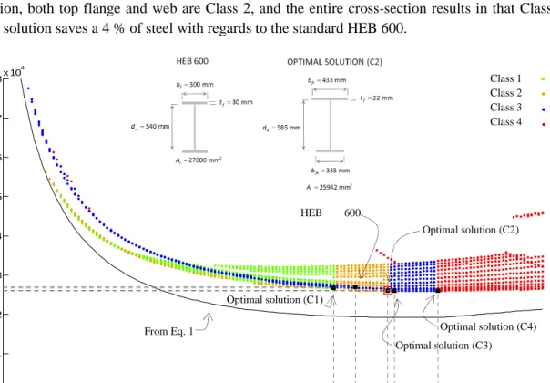
obtained and the optimal section, for which the dimensions are: dw =585 mm; 15, 50
w
t = mm tf =22 mm; bft =433 mm; bfb =334 mm; At =25942 mm2. For this section, both top flange and web are Class 2, and the entire cross-section results in that Class. The solution saves a 4 % of steel with regards to the standard HEB 600.
Figure 15. Cross-sectional area At of the solutions in terms of web depth dw for simultaneous compression and
bending moment about strong y-y
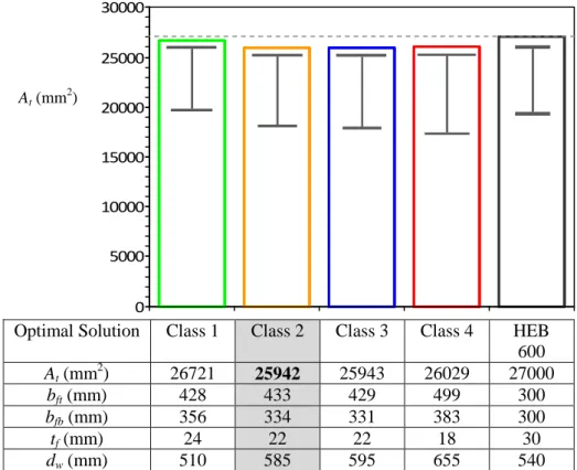
Figure 16 shows the obtained optimal results for each Class of sections. In this case, as in the former example, once again, all of them have a less cross-sectional area than the standard HEB600. There are two of them, solutions for Classes 2 and 3, which are almost the same area (slight differences in dimensions of flanges and web result in just 1 mm2 less in cross-sectional area for solution in Class 2).
100 200 300 400 500 600 700 800 0 1 2 3 4 5 6 7 8x 10 4 dw (mm) A t (m m 2) From Eq. 1 HEB 600 (C2) Optimal solution (C2) Optimal solution (C1) Optimal solution (C3) Optimal solution (C4) Class 1 Class 2 Class 3 Class 4
Figure 16. Comparison between the dimensions of different optimal solutions for each Class and HEB 600, for simultaneous compression and bending moment about strong y-y.
Figure 17. Cross-sectional and flange area in terms of dw, for solutions of tf = 20 mm and forcing both flanges
to be equal (i.e. doubly-symmetrical cross-section) for simultaneous compression and bending moment about strong y-y. From Eq. 1 Optimal solution (C4) HEB 600 (C2) After refinement Cross-section Flange 100 200 300 400 500 600 700 800 0 1 2 3 4 5 6 7 8x 10 4 dw (mm) A ( m m 2) Class 3 Class 4 No solutions with the
restriction bft = bfc 0 5000 10000 15000 20000 25000 30000
Optimal Solution Class 1 Class 2 Class 3 Class 4 HEB 600 At (mm 2 ) 26721 25942 25943 26029 27000 bft (mm) 428 433 429 499 300 bfb (mm) 356 334 331 383 300 tf (mm) 24 22 22 18 30 dw (mm) 510 585 595 655 540 At (mm 2 )
As the procedure is completely general, the doubly-symmetrical cross-section may be extrapolated without loss of generality. If the width of both flanges are forced to be equal, the optimal solution corresponds to a flange thickness of tf =20 mm and dw =625 mm;
15, 50
w
t = mm bft =396 mm; bfb =396 mm; 2
26303 mm
t
A = . Figure 17 represents both the cross-sectional and flange areas for doubly-symmetrical cross-section with tf =20 mm in function of the height of the web. For this figure it is evident that solutions only exist for values of dw from 420 mm, being the sections in Class 3 or 4. The standard HEB600 is included in the
list of possible solutions in Class 2.
3.4.
Global optimization
In order to extend the former optimization procedure to other values of web’s thickness, tw, the above process has been applied to several values of tw between 6 mm and 19 mm for the axial compression and bending moment about the strong axis denoted as combination C (see Figure 8). The optimal cross-section (i.e., with minimum area) obtained for each class of cross-section [9] for each thickness of the web can be identify in Figure 18. This figure shows that the smallest area that fulfil all the EC3 [9] requirements corresponds to cross-section in class 4 with tw = 8 mm. This optimal section needs to be stiffened because the slenderness of the web is too high. The optimum cross-section in class 3 and in Class 1 and 2 appears for tw = 13,5 mm and tw = 14,5 mm, respectively. In such cases the slenderness of the web is low enough that transverse stiffeners are not needed. In Figure 18, the optimal solutions obtained for the value of the thickness of the web adopted in the former sections (tw of the standard HEB 600) have also been indicated.
Figure 18. Optimal (i.e. minimum) cross-sectional area in terms of tw obtained for each class of cross-section
and for simultaneous compression and bending moment about strong y-y.
At ( m m 2) x 1043 tw (mm) tw = 15.5 mm 22 24 26 28 30 32 34 36 38 5 6 7 8 9 10 11 12 13 14 15 16 17 18 19 20 Class 1 Class 2 Class 3 Class 4 tw = 15.5 mm
4.
Conclusions
As has been explained and demonstrated in this work, employed symmetrical cross-sections are usually not, in most of the cases, the optimal solutions. This work presents an iterative procedure in order to get the optimal solution for the I-shaped cross-section of a steel beam-column member subject to an external axial load and bending about strong axis. The process is based on RSD diagrams for optimizing the longitudinal reinforcing steel in reinforced concrete sections and completes the procedure proposed by Gil-Martín et al. [1] for obtaining these optimal solutions with steel sections in Class 1 according to Eurocode 3. This method allows engineers to choose among all the possible solutions: compact, non-compact and slender sections, obtaining important savings in steel and hence leading to reductions in greenhouse gas emissions.
Acknowledgements
The present work was financed by the Spanish Ministry of Education. The first author is a Spanish Government PhD fellow (FPU grant AP 2010-3707). This support is gratefully acknowledged. As indicated, this work has been published by Journal of Steel Constructional Research. This publication is also gratefully acknowledged.
References
[1] Gil-Martín LM, Aschheim M, Hernández-Montes E. Proportioning of steel beam-column members based on RSD optimization methodology. Engineering Structures 2008; 30(11): 3003-11.
[2] Hernández-Montes E, Aschheim M, Gil-Martín LM. Impact of optimal longitudinal reinforcement on the curvature ductility capacity of reinforced concrete column sections. Magazine of Concrete Research 2004; 56(9): 499-14.
[3] Hernández-Montes E, Gil-Martín LM, Aschheim M. Design of concrete members subjected to uniaxial bending and compression using reinforcement sizing diagrams. ACI Structural Journal 2005; 102(1): 150-9.
[4] Hernández-Montes E, Gil-Martín LM. Hormigón armado y pretensado: concreto reforzado y preesforzado. Granada: Universidad de Granada, Grupo de Investigación TEP-190 Ingeniería e Infraestructuras; 2007.
(http://www.ugr.es/~emontes/prensa/HormigonEstructural.pdf)
[5] Comité Europeo de Normalización, Agencia Española de Normalización. UNE EN 1998-1: Eurocódigo 8: Proyecto de estructuras sismorresistentes. Parte 1: Reglas generales, acciones sísimicas y reglas para edificación. Madrid: Aenor; 2011b.
[6] Llago Acero R, García Rodríguez P. Composite twin-girder bridges: A competitive solution for medium span bridges. Revista de Obras Publicas 2010; 157(3516): 29-18.
[7]Brozzetti J. Design development of steel-concrete composite bridges in France. Journal of Constructional Steel Research 2000; 55(1–3): 229-15.
[8] Ryu H-K, Youn S-G, Bae D, Lee, Y-K. Bending capacity of composite girders with Class 3 section. Journal of Constructional Steel Research 2006; 62(9): 847-9.
[9] Dirección General de carreteras. Obras de paso de nueva construcción: conceptos generales. Madrid: Ministerio de Fomento; 2005.
[10] Comité Europeo de Normalización, Agencia Española de Normalización. UNE EN 1993-1-1: Eurocódigo 3: Proyecto de estructuras de acero. Parte 1-1993-1-1: Reglas generales y reglas para edificios. Madrid: Aenor; 2008.
[11] Rugarli P. Classification of I- or H-shaped cross-sections under mixed internal actions. Journal of Constructional Steel Research 2009; 65(8-9): 159-8.
[12] Steel Construction Manual (AISC 325-11). 14th ed. Chicago: AISC American Institute of Steel Construction; 2009.
[13] Comité Europeo de Normalización, Agencia Española de Normalización. UNE EN 1993-1-5: Eurocódigo 3: Proyecto de estructuras de acero. Parte 1-1993-1-5: Placas planas cargadas en su plano. Madrid: Aenor; 2011a.