DEVELOPMENT AND CHARACTERIZATION OF RAFFIA PALM FIBER REINFORCED POLYMER MATRIX COMPOSITES
A Thesis Submitted to the College of
Graduate and Postdoctoral Studies
In Partial Fulfillment of the Requirements
For the Degree of Master of Science
In the Department of Mechanical Engineering
University of Saskatchewan
Saskatoon
By
Opeoluwa Elijah Fadele
i
PERMISSION TO USE
In presenting this thesis in partial fulfillment of the requirements for a Postgraduate degree from the University of Saskatchewan, I agree that the Libraries of this University may make it freely available for inspection. I further agree that permission for copying of this thesis in any manner, in whole or in part, for scholarly purposes may be granted by Prof. Ikechukwuka Oguocha and Prof. Akindele Odeshi, the professors who supervised my thesis work or in their absence, by the Head of the Department or the Dean of the College in which my thesis work was done. It is understood that any copying or publication or use of this thesis or parts thereof for financial gain shall not be allowed without my written permission. It is also understood that due recognition shall be given to me and to the University of Saskatchewan in any scholarly use which may be made of any material in my thesis.
Requests for permission to copy or to make other uses of materials in this thesis in whole or part should be addressed to:
Head of the Department of Mechanical Engineering 57 Campus Drive
University of Saskatchewan
Saskatoon, Saskatchewan S7N 5A9 Canada
OR
Dean
College of Graduate and Postdoctoral Studies University of Saskatchewan
116 Thorvaldson Building, 110 Science Place Saskatoon, Saskatchewan S7N 5C9
ii ABSTRACT
Due to high energy consumption and environmental pollution generated in the processing and use of synthetic fibers, the need for replacement of these fibers with natural fibers in composites manufacture has increased. The advantages of natural fibers over synthetic fibers include low cost, biodegradability and non-toxicity. In this study, as received raffia palm fibers (RPF) and those whose surface were chemically modified using 10 wt.% NaOH for 5 h at 60oC and 0.6 M H2SO4 for 2 h at 100oC were compression molded to produce HDPE matrix composites containing 5, 10, 20, and 30 wt.% of RPFs. Morphological, thermal, tensile, physical and structural properties of the fibers before and after treatment were investigated using scanning electron microscopy (SEM), differential scanning calorimetry (DSC), InstronTM machine and Fourier transform infrared spectroscopy (FTIRS). The effects of chemical treatments of the fiber and varying fiber loadings on the mechanical, physical and thermal properties of RPFs reinforced HDPE composites were investigated. Mechanical and thermal properties of the composites were investigated using InstronTM machine and the differential scanning calorimetry (DSC), respectively. The effect of chemical modification on water uptake of the composites was also studied.
Surface chemical treatment of the RPFs by soaking in 10 wt.% NaOH for 5 h at 60oC or 0.6 M H2SO4 for 2 h at 100oC resulted in 22% increase in the cellulose content of the fiber. SEM results showed that the RPF comprises of several elemental fibers, which are tightly packed together with each having its lumen at the center. FTIR spectroscopy results indicated reduction and disappearance of some non-cellulosic components in the treated RPFs. Although, there was an increase in the degradation temperature of the treated fibers, tensile strength and water absorption capacity of the treated fibers reduced in comparison to non-treated fibers. The use of RPFs (surface treated or not) in reinforcing HDPE led to increase in tensile modulus, flexural strength, flexural modulus and crystallization temperature of the composite when compared to unreinforced HDPE. The rate of water absorption for composites containing treated fibers is lower than that for composites containing untreated fiber. The tensile strength, impact strength and melting temperature of HDPE decreased with addition of either untreated or treated RPFs. Results also showed that increasing fiber content decreased the tensile strength, flexural strength, impact energy and the melting temperature of the composites. However, increase in tensile modulus, flexural
iii
modulus, water absorption and crystallization temperature of the composites was observed as the fiber content was increased.
iv
ACKNOWLEDGEMENTS
I would like to express my sincere gratitude to my supervisors, Prof. Ikechukwuka Oguocha and Prof. Akindele Odeshi for the opportunity to carry out my M.Sc. study under their guidance. The kindness, time, professional and scientific contributions to the success of my study are deeply appreciated. The contributions of Prof. Duncan Cree and Prof. Tabil Lope, my advisory committee members are greatly appreciated. I thank Dr. Majid Soleimani for his time, advice, insightful and valuable comments which have remarkably contributed to the success of this study.
My appreciations also go to Mr. Rob Peace and Dr. Chithra Karunakaran for their time, advice and patience in training me on most of the equipment used during my MSc. program. The extensive technical support received from Mr. Nan Fang Zhao, Dr. Melanie Fauchoux, Prof. Lee Wilson and Abdalla Karoyo in carrying out many of my experiments is also acknowledged. My appreciation also goes to Fraser Waldie my contact at Nova Chemicals Corporation who ensure I got the right HDPE polymer for my research. I am grateful.
I would like to sincerely appreciate the efforts of my parents, Pastor and Pastor (Mrs.) Fadele for their support, prayers, words of encouragement; they gave to me both morally and financially. I pray that the Almighty God will give them life and strength to eat the good fruit of their labour. To my uncle (Pastor James Fadel) who took it upon himself to see me succeed in my academic pursuit, daddy I am eternally grateful.
To my friends Emmanuel Awoyele, Ahmed Tiamiyu, and Jimmy Fung, your contribution and moral supports towards the completion of this thesis cannot be quantified. Thank you. Lastly, I am very grateful to everybody who has been a source of help, inspiration and guide, and my second family (Jesus House Family), I am grateful to have met you. God, bless you all.
v
DEDICATION
I DEDICATE MY THESIS FIRST TO THE SOURCE OF ALL LIFE AND MY KING
vi
TABLE OF CONTENTS
PERMISSION TO USE …...………..i
ABSTRACT ………..………...…..ii
ACKNOWLEDGEMENTS ………..……….…..iv
DEDICATION ……….………..v
TABLE OF CONTENTS ………...vi
LIST OF TABLES ………...………....xi
LIST OF FIGURES ………..……….xiii
LIST OF ABBREVIATIONS AND SYMBOLS ………...xviii
CHAPTER 1: INTRODUCTION ……….…..………..1
1.1 Overview ………..1
1.2 Objectives ……….3
1.3 Thesis organization ……….……….3
CHAPTER 2: LITERATURE REVIEW ………...….….4
2.1 Composites Materials ……….…………..4
2.2 Classification of Composite Materials Based on the Matrix ………..……….4
2.2.1 Metal Matrix Composites ………...5
2.2.2 Ceramics Matrix Composites ………...5
2.2.3 Polymer Matrix Composites ………...6
2.3 Type of Reinforcements for Composite Materials ………...6
2.3.1 Particles ………....6
2.3.2 Whiskers ………..…...7
2.3.3 Fibers ………....7
2.3.3.1Synthetic Fibers ………....7
2.3.3.2Natural Fibers ………...7
2.4 Chemical Composition of Natural Fibers ………8
vii
2.5.1 Moisture Adsorption ………..….11
2.5.2 Water Absorption ………...12
2.5.3 Thermal Conductivity ………...12
2.5.4 Thermal Analysis of Natural Fibers ………...12
2.5.5 FTIR and Raman Spectroscopy ………...13
2.6 Chemical Treatment of Natural Fibers ………...13
2.6.1 Sodium Hydroxide (NaOH) Treatment ………...14
2.6.2 Sulphuric Acid (H2SO4) Treatment ………15
2.6.3 Silane Treatment ………...15
2.7 Processing Techniques for Natural Fiber Reinforced Composites ……….……...16
2.7.1 Extrusion Molding and Extrusion Compounding ………...……...16
2.7.2 Compression Molding ………...18
2.7.3 Injection Molding ………...18
2.8 Characterization of Natural Fibers Reinforced Polymer Matrix Composites …………...19
2.8.1 Water Absorption ………...19
2.8.2 Thermal Properties ………...20
2.8.3 Mechanical Properties ………...21
2.9 Application of Natural Fiber Reinforced Polymer Matrix Composites ………...22
2.10 Summary ………..….22
CHAPTER 3: MATERIALS AND EXPERIMENTAL METHODS ……...………...24
3.1 Materials ………...24
3.2 Characterization of Raffia Palm Fibers (RPF) .………...25
3.2.1 Length Measurement ………...25
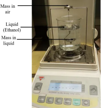
3.2.2 Density Measurement …...………...25
3.2.3 Determination of Chemical Composition of RPFs ………...27
3.2.4 Sample Preparation for Microscopy …...…...……….28
3.2.5 Mid Infrared Spectromicroscopy (Mid – IRS) ..………...28
3.2.6 Tensile Test ………...30
3.2.7 Statistical Analysis ………....………...30
viii
3.2.9 Water Absorption of RPFs ……….32
3.2.10 X-ray Diffraction (XRD) ………...……….32
3.2.11 Chemical Treatments of RPFs ………...……….33
3.2.12 Colour Measurement ………….……….34
3.2.13 Differential Scanning Calorimetry (DSC) .……….35
3.2.14 FTIR and Raman Spectroscopy ………..36
3.3 Manufacture of RPF Reinforced High Density Polyethylene Composites …………..….….37
3.3.1 Extrusion Machine and Process of Mixture ………...…...…….38
3.3.2 Compression Molding Equipment and Process ………..40
3.4 Characterization of RPF Reinforced HDPE Composites ………..……….42
3.4.1 Density Measurement …..………..……….42
3.4.2 Tensile Test of Composites ………...……….43
3.4.3 Flexural Test of Composites ...………..……….……….45
3.4.4 Charpy Impact Test of Composites .………..………...……….……….46
3.4.5 Water Absorption .………..………..…….……….48
3.4.6 Thermal Analysis .………..………..………….……….48
3.4.7 Microscopic Investigations of Composites .………..……….49
CHAPTER 4: RESULTS AND DISCUSSION .……….50
4.1 Characterization of Raffia Palm Fiber (RPF) .………..……….……….50
4.1.1 Chemical Composition of RPF .………..………...…….50
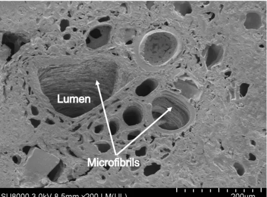
4.1.2 Microstructure of RPF .………..……….………...…….53
4.1.3 Moisture Adsorption and Water Absorption .……...……….…….57
4.1.4 Mechanical Properties .………..……….………...…….60
4.1.5 Statistical Analysis .………..……….…………....…….64
4.1.6 Colour Measurements of RPFs .………..………....………...…….66
4.1.7 Synchrotron Based Fourier Transform Infrared Spectromicroscopy .……...…….67
4.1.8 FT-Infrared and Raman Spectroscopy .………..………...…….71
4.1.9 X-ray Diffraction .………..……….………....………...…….74
4.1.10 DSC Measurements .………..……….………....………...…….75
ix
4.2.1 The Effect of Fiber Addition on the Density of High Density Polyethylene ....…….80
4.2.2 Tensile Properties Raffia Palm Fiber Reinforced HDPE .……….…….83
4.2.3 Fractography of Failed Tensile Specimens .………..……….…...…….85
4.2.4 The Effect of Fiber Reinforcement on the Flexural Properties of HDPE .………….87
4.2.5 The Effect of Fiber Addition on the Energy Absorbed of HDPE .….…...…....…….89
4.2.6 SEM Analysis of Fractured Charpy Impact Samples .………..………...…….91
4.2.7 The Effect of Fiber Addition on Thermo-Physical Properties of HDPE .…….…….92
4.2.8 The Influence of Fiber Addition on the Water Absorption Capacity of HDPE …….96
4.3 Summary .………..………...………...…… 99
CHAPTER 5: CONCLUSIONS AND RECOMMENDATIONS ………...…...101
5.1Conclusions ………..………...………...…...101
5.2Recommendations for Future Work ………..………...…102
REFERENCES ………..………...…………..…103
APPENDICES ..………...…..………...………...…… 119
APPENDIX A …..…………..………...………...…… 120
Ankom Fiber ADF, NDF and ADL Methods APPENDIX B …..…………..………...………...…… 131
Statistical Analysis of Variation of RPF Colour with Fiber Treatment APPENDIX C …..…………..………...………...…… 134
Result and Statistical Analysis of the Effect of Fiber Content and Fiber Treatment on the Density of RPF reinforced HDPE APPENDIX D …..…………..………...………...…… 139
Result and Statistical Analysis of the Effect of Fiber Content and Fiber Treatment on the Tensile Properties of RPF reinforced HDPE APPENDIX E …..…………..………...………...…… 148
Result and Statistical Analysis of the Effect of Fiber Content and Fiber Treatment on the Flexural Properties of RPF reinforced HDPE
x
APPENDIX F …..…………..………...………...…… 157 Result and Statistical Analysis of the Effect of Fiber Content and Fiber Treatment on the Impact Strength of RPF reinforced HDPE
APPENDIX G …..…………..………...………...…… 166 Result of the Effect of Fiber Content and Fiber Treatment on the Density of RPF
reinforced HDPE
APPENDIX H …..…………..………...………...…… 167 Result and Statistical Analysis of the Effect of Fiber Content and Fiber Treatment on the Water Absorption Behaviour of RPF reinforced HDPE
xi
LIST OF TABLES
Table 2.1 Chemical composition of some natural fibers. 10
Table 2.2 Mechanical properties of some natural and synthetic fibers. 11
Table 3.1 Humidity generator setup parameters. 31
Table 4.1 Chemical composition (as received basis) of raffia palm fibers. 51 Table 4.2 Chemical composition (dry matter basis) of raffia palm fibers. 52 Table 4.3 Mechanical properties of chemically treated raffia palm fibers. 64 Table 4.4 ANOVA test results for tensile strength of raffia palm fibers with varying fiber
lengths of 45, 70, 95, 120 and 145 mm.
64
Table 4.5 ANOVA test results for %elongation for 25 mm gauge length of raffia palm fibers with varying fiber lengths of 45, 50, 55, 60, 65, 70 and 75 mm.
65
Table 4.6 ANOVA test results for tensile strength for 50 mm gauge length of raffia palm fibers with varying crosshead speed of 0.5, 1, 1.5 and 2 mm/min.
65
Table 4.7 ANOVA test results of fiber treatments on the tensile strength at 45 mm fiber length of raffia palm fibers.
66
Table 4.8 ANOVA test results of fiber treatments on % elongation at 25 mm gauge length of raffia palm fibers.
66
Table 4.9 Variation of raffia palm fiber colour with NaOH and H2SO4 treatment. 66 Table 4.10 Thermal properties of untreated and treated raffia palm fibers obtained from
differential scanning calorimetry analysis.
79
Table B.1 ANOVA results for colour variations of raffia palm fibers with fiber treatment. 131 Table C.1 Effect of raffia palm fiber addition on the density of high density polyethylene
composites.
134
Table C.2 SigmaPlot two-way analysis of variance of the effect of fiber content and fiber treatment on the density of raffia palm fiber reinforced high density polyethylene.
134
Table D.1 Effect of raffia palm fiber addition on the tensile properties of high density polyethylene composites.
139
Table D.2 SigmaPlot two-way analysis of variance of the effect of fiber content and fiber treatment on the tensile strength of raffia palm fiber reinforced high density polyethylene.
xii
Table D.3 SigmaPlot two-way analysis of variance of the effect of fiber content and fiber treatment on the Young’s modulus of raffia palm fiber reinforced high density polyethylene.
143
Table E.1 Effect of raffia palm fiber content on the flexural properties of high density polyethylene composites.
148
Table E.2 SigmaPlot two-way analysis of variance of the effect of fiber content and fiber treatment on the flexural strength of raffia palm fiber reinforced high density polyethylene.
148
Table E.3 SigmaPlot two-way analysis of variance of the effect of fiber content and fiber treatment on the flexural modulus of raffia palm fiber reinforced high density polyethylene.
152
Table F.1 Impact properties of unreinforced and raffia palm fiber reinforced high density polyethylene at different temperatures.
157
Table F.2 SigmaPlot three-way analysis of variance of the effect fiber content, fiber treatment and temperature on the impact strength of raffia palm fiber reinforced high density polyethylene.
158
Table G.1 Effect of untreated and treated raffia palm fibers on thermo-physical properties of high density polyethylene composites.
166
Table H.1 Effect of untreated and treated raffia palm fibers on water absorption behaviour of high density polyethylene composites.
167
Table H.2 SigmaPlot two-way analysis of variance of the effect fiber content and fiber treatment on the water absorption behaviour of raffia palm fiber reinforced high density polyethylene.
xiii
LIST OF FIGURES
Figure 1.1 Photo showing (a) the location of raffia palm tree and (b) raffia palm tree. 2 Figure 2.1 Classification of natural fibers according to origin. 8 Figure 2.2 Applications of natural fiber reinforced polymer matrix composites. 23 Figure 3.1 Photographs of raffia palm fiber (a) before cleaning and (b) after washing and
drying.
24
Figure 3.2 Flowchart for raffia palm fiber processing, treatment and characterization. 25 Figure 3.3 Images of (a) weighing instrument for ground raffia palm fibers and (b) gas
pycnometer instrument for density measurement.
26
Figure 3.4 Ankom 200 fiber analyzer used for determining the chemical composition of
raffia palm fibers.
27
Figure 3.5 Image showing (a) frozen raffia palm fibers in liquid nitrogen and (b) Leica CM1950 cryostat machine.
28
Figure 3.6 Bruker Vertex 70v Interferometer / Hyperion 3000 IR Microscope. 29 Figure 3.7 Picture showing schematic drawing of a single raffia palm fiber prepared for
tensile test.
30
Figure 3.8 Humidity generator used for moisture absorption measurement. 32 Figure 3.9 Images of sodium hydroxide solution (a) before treatment and (b) after
treatment
34
Figure 3.10 Images of sulfuric acid solution (a) before treatment and (b) after treatment. 34 Figure 3.11 HunterLab spectrocolorimeter used for colour measurements. 35
Figure 3.12 Renishaw Raman inVia Reflex microscope. 36
Figure 3.13 Flowchart for raffia palm fiber reinforced high density polyethylene composite processing and characterization.
37
Figure 3.14 Processing chart showing the mixing of untreated, alkaline and acidic treated raffia palm fibers with high density polyethylene to make raffia palm fiber reinforced high density polyethylene composites. M1 = 5 wt.%, M2 = 10 wt.%, M3 = 20 wt.%, M4 = 30 wt.% of fiber, NT = no treatment of the fiber, T1=
treatment with 10% w/v aqueous NaOH solution at 60oC for 5 h, T2 =
treatment with 0.6 M H2SO4 solution at 100oC for 2 h.
xiv
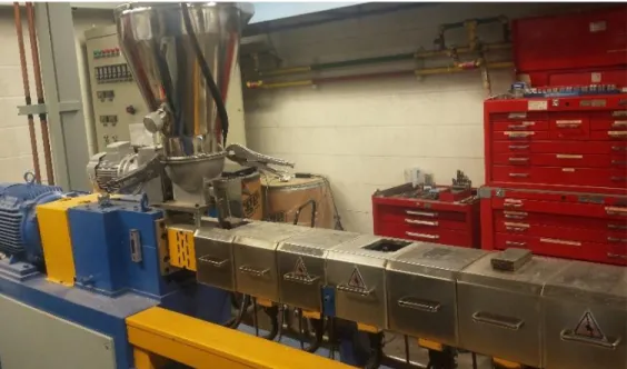
Figure 3.15 Twin screw extrusion machine for producing extrudates required for composites manufacture.
39
Figure 3.16 Images of (a) water bath and (b) cooling strand pelletizer. 39
Figure 3.17 Retsch knife grinding mill. 40
Figure 3.18 Images of the (a) mold, mold releasing agent and molding plates and (b) compression molding machine.
40
Figure 3.19 Images of composites plates from extruded pellets showing surface porosity. 41 Figure 3.20 Images of composites plates from ground extruded pellets (no surface
porosity).
42
Figure 3.21 Apparatus used for measuring densities of compression molded composites and high-density polyethylene.
43
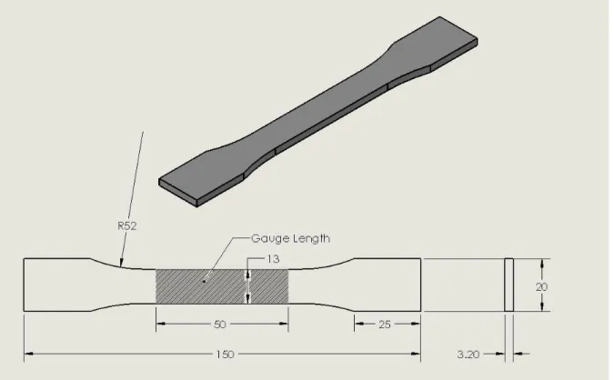
Figure 3.22 Dog-bone shaped specimens for tensile test. 44
Figure 3.23 InstronTMtensile machine equipped with a clip-on extensometer for determining
Young’s modulus of test specimens.
44
Figure 3.24 A picture showing a typical flexural test on a sample of 10% composites. 45 Figure 3.25 Charpy impact testing machine used in this study. 47 Figure 3.26 Broaching machine used in notching the charpy impact samples. 47
Figure 3.27 Charpy impact test samples. 48
Figure 3.28 Water absorption tests on composites. 49
Figure 3.29 A photograph of the scanning electron microscope used for microstructural investigations.
49
Figure 4.1 Scanning electron micrographs showing transverse cross-section of (a) untreated, (b) alkaline treated and (c) acidic treated raffia palm fibers.
53
Figure 4.2 Scanning electron micrograph showing enlarged view of the inner section (lumen) of raffia palm fiber (transverse section).
54
Figure 4.3 Scanning electron micrograph showing enlarged view of the middle section (cortex) of raffia palm fiber (transverse section).
55
Figure 4.4 Scanning electron micrographs showing the longitudinal surface of untreated raffia palm fibers.
56
Figure 4.5 Scanning electron micrographs showing the longitudinal surface of raffia palm fibers treated with NaOH.
xv
Figure 4.6 Scanning electron micrographs showing the longitudinal surface of raffia palm fibers treated with sulphuric acid.
57
Figure 4.7 Moisture adsorption behaviour of untreated raffia palm fiber at 50% relative humidity and 23oC.
58
Figure 4.8 Water absorption behaviour of untreated raffia palm fiber. 59 Figure 4.9 Water absorption behaviour of alkali and acidic treated raffia palm fiber. 60 Figure 4.10 A typical stress-strain curve obtained for a raffia palm fiber at room temperature. 61
Figure 4.11 Variation of fiber strength to fiber length. 61
Figure 4.12 Variation of percentage elongation to fracture of raffia palm fibers with fiber length.
63
Figure 4.13 Variation of tensile strength of raffia palm fibers with the crosshead speed. 63 Figure 4.14 Synchrotron based Fourier transform infrared spectra of untreated raffia palm
fiber.
68
Figure 4.15 Synchrotron base Fourier transform infrared spectromicroscopy imaging of the transverse section of untreated raffia palm fiber showing (a) the map region of interest and chemical distribution of (b) cellulose (1165 cm-1), (c) lignin (1503 cm-1) and (d) pectin (1750 cm-1).
69
Figure 4.16 Synchrotron base Fourier transform infrared spectromicroscopy imaging of the lower left region of untreated raffia palm fiber showing (a) the map region of interest and chemical distribution of (b) cellulose (1165 cm-1), (c) lignin (1503 cm-1) and (d) pectin (1750 cm-1).
71
Figure 4.17 Fourier transform infrared spectra of untreated, alkali and acid treated raffia palm fibers.
72
Figure 4.18 Raman spectra of (a) untreated, (b) alkali and (c) acidic treated raffia palm fibers. 73 Figure 4.19 Result of X-ray diffraction analysis on untreated, alkaline and acidic treated raffia
palm fibers.
74
Figure 4.20 Differential scanning calorimetry thermograms obtained for untreated (a) air-dried at 23oC and (b) oven-dried raffia palm fibers at 60oC.
76
Figure 4.21 Differential scanning calorimetry thermograms obtained for alkaline treated raffia palm fiber.
77
Figure 4.22 Differential scanning calorimetry thermograms obtained for acidic treated raffia palm fiber.
xvi
Figure 4.23 Effect of fiber content and chemical treatment on the bulk density of raffia palm fiber reinforced high density polyethylene composites.
80
Figure 4.24 A comparison of the bulk densities of untreated raffia palm fiber reinforced high density polyethylene composites obtained from measurements and those determined from the rule of mixture.
81
Figure 4.25 A comparison of the bulk densities of NaOH treated raffia palm fiber reinforced high density polyethylene composites obtained from measurements and those determined from the rule of mixture.
82
Figure 4.26 A comparison of the bulk densities of H2SO4 treated raffia palm fiber reinforced high density polyethylene composites obtained from measurements and those determined from the rule of mixture.
82
Figure 4.27 Effect of fiber content and chemical treatment on tensile strength of raffia palm fiber reinforced high density polyethylene composites.
83
Figure 4.28 Effect of fiber content and chemical treatment on Young’s modulus of raffia palm
fiber reinforced high density polyethylene composites.
84
Figure 4.29 SEM micrographs of fracture surfaces of tensile specimens of high density polyethylene composites reinforced with (a) 5 wt.% untreated, (b) 30 wt.% untreated, (c) 5 wt.% NaOH treated, (d) 30 wt.% NaOH treated, (e) 5 wt.% H2SO4
treated and (f) 30 wt.% H2SO4 treated raffia palm fibers.
86
Figure 4.30 Effect of fiber content and fiber treatment on flexural strength of raffia palm fiber
reinforced high density polyethylene matrix composites.
88
Figure 4.31 Effect of fiber content and fiber treatment on flexural modulus of raffia palm fiber
reinforced high density polyethylene matrix composites.
88
Figure 4.32 Effect of fiber content on the impact energy absorbed of high density polyethylene composites reinforced with untreated raffia palm fibers.
90
Figure 4.33 Effect of fiber content on the impact energy absorbed of high density polyethylene composites reinforced with NaOH treated raffia palm fibers.
90
Figure 4.34 Effect of fiber content on the impact energy absorbed of high density polyethylene composites reinforced with H2SO4 treated raffia palm fibers.
91
Figure 4.35 Scanning electron micrographs of charpy impact fracture surfaces at room temperature of high density polyethylene composites reinforced with (a) 5
xvii
wt.% untreated, (b) 30 wt.% untreated, (c) 5 wt.% NaOH treated, (d) 30 wt.% NaOH treated, (e) 5 wt.% H2SO4 treated and (f) 30 wt.% H2SO4 treated raffia palm fibers.
Figure 4.36 Effect of fiber content and fiber treatment on melting temperature of raffia palm fiber reinforced high density polyethylene matrix composites.
93
Figure 4.37 Effect of fiber content and fiber treatment on crystallization temperature of raffia palm fiber reinforced high density polyethylene matrix composites.
94
Figure 4.38 Effect of fiber content and fiber treatment on fractional crystallinity of raffia palm fiber reinforced high density polyethylene matrix composites.
95
Figure 4.39 Effect of fiber content on the water absorption behaviour of high density polyethylene composites reinforced with untreated raffia palm fibers.
97
Figure 4.40 Effect of fiber content on the water absorption behaviour of high density polyethylene composites reinforced with of NaOH treated raffia palm fibers.
97
Figure 4.41 Effect of fiber content on the water absorption behaviour of high density polyethylene composites reinforced with H2SO4 treated raffia palm fibers.
98
Figure 4.42 Typical scanning electron micrograph showing the presence of pores in high density polyethylene compression molded samples.
xviii
LIST OF ABBREVIATIONS AND SYMBOLS ABBREVIATIONS
𝑎∗ Chromacity coordinates (green to red) ADF Acid detergent fiber
ADL Acid detergent lignin
𝑏 Flexural sample width (mm)
𝑏∗ Chromacity coordinates (blue to yellow)
𝐵𝐺 Between groups
CI Crystallinity index
CMC Ceramics matrix composite
𝑑 Flexural sample thickness (mm)
𝐷 Deflection of flexural sample (mm)
𝐷𝑓 Degree of freedom
DMB Dry matter basis
DSC Differential scanning calorimeter
𝐸 Young’s modulus (GPa)
𝐸𝑓 Flexural modulus (GPa)
𝐸𝑖 Impact energy (J)
FRP Fiber reinforced polymer or Fiber reinforce plastic FRPC Fiber reinforced polymer composite
FTIR Fourier transform infrared
FTIRS Fourier transform infrared spectroscopy HDPE High density polyethylene
𝐿 Length of support span (mm)
𝐿∗ Chromacity coordinates (white to black)
Lo Gauge length (mm)
𝑚 Slope of the load-deflection curve MMC Metal matrix composite
𝑀𝑆 Mean square
MSDC Modulated differential scanning calorimeter NDF Neutral detergent fiber
xix
NF Natural fiber
NFRP Natural fiber reinforced polymer
NT Non-treated
𝑃 Flexural load (N)
PMC Polymer matrix composite
𝑟 Maximum flexural strain
𝑅 Crosshead speed (mm/min)
RH Relative humidity
RPF Raffia palm fiber
RT Room temperature (23oC) SEM Scanning electron microscope
SF Synthetic fiber
𝑆𝑆 Sum of squares
Tm Melting temperature (oC)
𝑊𝐺 Within groups
XRD X-ray Diffraction
𝑍 Rate of straining of the outer fiber (mm/min)
SYMBOLS
∆𝐸 Colour index
𝜌𝑐 Density of composite (gcm-3)
𝜌𝑓 Density of fiber (gcm-3)
𝜌𝑙 Density of liquid (gcm-3)
𝜎𝑓 Flexural strength (MPa)
1 CHAPTER 1 INTRODUCTION 1.1 Overview
A composite is a multi-component material consisting of two or more different components that are chemically dissimilar and separated by a distinct interface. The properties of composite materials are functions of the properties of two constituent materials: the continuous material called matrix and the discrete material used in reinforcing the matrix, i.e. the reinforcement. The dispersed reinforcing materials are usually stiffer and stronger than the matrix [1]. The properties of a composite depend on the properties of its constituents as well as the volume fraction, geometry and distribution of the reinforcing component. Most composites materials are developed to achieve optimum combinations of mechanical properties such as strength, stiffness and toughness [2].
The mechanical properties of polymers are inadequate for many structural purposes, particularly their strength and stiffness which are lower than those of ceramics and metals [3]. This difficulty is commonly overcome by reinforcing polymers with other materials such as ceramics, glasses, metals and carbon-based materials. Reinforcing polymers with these materials gives rise to improved mechanical properties and widens their structural applications. Synthetic fibers (SFs), whiskers and particles are used to reinforce polymers for a variety of applications in automobiles, sporting goods, household appliances, boats, as well as construction and packaging materials [4]. However, it is equally recognized that composites made from synthetic reinforcements pose severe environmental pollution problems [5]. Hence, there exist an increasing interest in the use of natural fibers (NFs) for making polymer matrix composites (PMCs). Natural fibers are sourced mostly from plants. As a result, they are inexpensive, renewable and biodegradable. Some NFs have mechanical properties comparable to those of some synthetic fibers [6]. NF composites with thermoplastic and thermoset matrices have been embraced by European car manufacturers and suppliers for door panels, seat backs, headliners, package trays, dashboards, and interior parts [7]. Natural fibers derived from flax, sisal, and hemp plants have been used in making these products [9].
Although NFs have some attractive qualities, they have some shortcomings which limits their use in several structural applications. They have high variability in properties [8]. They have high
2
affinity to water which is caused by cellulose and hemicellulose of NFs. This results in poor bonding and swelling in NF-reinforced PMCs and, consequently, poor mechanical performance. The use of chemical treatments and coupling agents could be effective in enhancing bonding with polymers. In composites fabrication, if the coupling between the reinforcement and the matrix is poor, a coupling agent will be needed for good mechanical properties.
Although several studies have been carried out to investigate the use of natural fibers such as flax [8–11], sisal [12–14], hemp [15–17], jute [18–20], kenaf [16,21–23], abaca [24–26], banana [3,20,27], coir [28–30] and ramie [31–33] in making PMCs, very little attention has been given to the potential use of raffia palm fiber in these composites [5]. Raffia palm fiber is a natural vegetable fiber like sisal, banana and abaca, which are extracted from the leaflets of raffia palm tree – Raphia farinifera (Fig. 1.1b).
Figure 1.1. Photo showing (a) the location of raffia palm tree [34] and (b) raffia palm tree [35].
Raffia palm tree are grown in the tropical region of Africa, Madagascar and South America [36,37]. There are about 28 different species of raffia fibers grown in the tropics, and they have different properties [38]. The entire raffia palm tree is used for various purposes: from its nuts, one extracts edible and cosmetic oil; from its sap, a white sweet alcoholic liquid is collected, known as palm wine. The fibers extracted from the leaves are used for making dresses, carpets, blankets, ligatures for grafting and as construction materials [5,39]. To date, there has been few studies on the microstructure, chemical properties and characterization of raffia fibers and raffia fibers reinforced polymer composite. Sandy and Bacon [39] studied the tensile properties of raw Raphia
3
farinifera from Madagascar. Anike et al. [40] investigated the effects of alkali treatments on the tensile and hardness properties of raffia palm fiber reinforced polyester resin composite. Elenga et al. [5,38,41] reported on the microstructure, physical and tensile properties of raw and alkali treated Raphia textilis. Different characterization techniques such as scanning electron microscope (SEM), X-ray diffraction (XRD), Fourier transform infrared spectroscopy (FTIRS) and Instron testing machine were used. However, the effects of reinforcing HDPE with varying weight fractions of raw, alkaline and sulphuric acid treated Raphia farinifera (from Nigeria) are yet to be studied.
1.2 Objectives
The long-term goal of the present research is to develop and characterize raffia palm fiber reinforced polymer composites using high density polyethylene as the matrix for structural application. To realize this goal, the following specific objectives were pursued:
1. Optimization of the surface chemistry of raffia palm fibers (RPFs) for enhanced interfacial adhesion with polymers.
2. Determination of the effects of surface modification on mechanical and physical properties of RPFs reinforced high density polyethylene.
After the realization of my objectives, my major research contributions to knowledge are:
1. The use of synchrotron Mid-IR to understand the spatial distribution and concentration of chemical compositions of raffia palm fibers.
2. The effects of chemical treatments on the water absorption behaviour of raffia palm fibers.
1.3. Thesis Organization
This thesis consists of five chapters. An overview of the project and research objectives are presented in Chapter 1. A review of previous work relevant to the research topic is provided in Chapter 2. Experimental materials and procedures including composite synthesis and characterization are discussed in Chapter 3. Chapter 4 presents and discusses the research results obtained from tests conducted in Chapter 3. The conclusions drawn from the analysis of the tests results and recommendations for future work are provided in Chapter 5.
5 CHAPTER 2 LITERATURE REVIEW
This chapter reviews the different characterization techniques associated with NFs, different technique used in manufacturing NFs reinforced polymer matrix composites. It also includes some techniques used in characterizing NFs reinforced polymer matrix composites and its applications.
2.1 Composites Materials
The aim of combining different materials in a composite is to produce a superior and unique material that combines the desired properties of the constituent materials while retaining their identities in the new product [42]. The driving force behind the development of most existing composites is their capability to be designed to provide the targeted material behavior [43]. Development of new composites materials has continued to attract attention in the manufacturing industry, as it offers opportunity to use weak materials with other desirable properties by simply strengthening them with stronger and stiffer reinforcing components such as fibers, whiskers or particles.
2.2 Classification of Composite Materials
Depending on the matrix material, a composite may be classified as metal, polymer, or ceramic matrix composite. In general, metals and polymers are reinforced with fibers, whiskers or particles to increase strength or stiffness or both. For ceramic-matrix composites, the reinforcing component is added mostly to improve fracture toughness [2]. For fiber-reinforced composites, the matrix material binds the fibers together and acts as the medium through which an externally applied stress is transmitted and distributed to the fibers through the interface while only a very small proportion of the applied load is carried by the matrix material [2]. The matrix also protects the individual fibers from surface damage due mechanical abrasion or chemical attack from the environment. The strength of the interface between the matrix and reinforcing component generally controls the mechanical properties of a composite [44].
6 2.2.1 Metal Matrix Composites (MMCs)
A metal matrix composites (MMCs) consists of a metal matrix that is reinforced by a ceramic fibers or particles to enhance stiffness and strength. Most MMCs commonly produced are based on light metal alloy matrices, especially magnesium, aluminum and titanium alloys. High temperature cobalt and nickel-based alloys are also reinforced with ceramic particles to create a class of MMCs called cermets. [45]. Reinforcing A359 aluminum alloy with 20 vol.% ceramic silicon carbide particles resulted in the production of car brake discs with high wear resistance and good mechanical strength [45]. Ceramic fiber reinforced aluminum alloys have been developed for making propeller shafts used in automobile. This resulted in a 50% weight reduction in comparison to the conventional steel shafts, and reduced number of applied bearings [45]. Lee and Sue [46] studied the effect of dynamic impact on carbon fiber reinforced 7075 Al matrix composites. It was found that the dynamic strength of the composite increased by 35%. Plasma electrolytic oxidation (PEO) method was used to make aluminum alloy 383- SiO2 particle composites for use in the production of engine block cylinder liners [47]. This reduced weight and manufacturing cost, while wear resistance increased by 85%.
2.2.2 Ceramics Matrix Composites (CMCs)
Ceramics have certain attractive properties such as high stiffness, hardness, compressive strength and relatively low density [48]. However, they are brittle and have low fracture toughness. CMCs are developed to retain the desirable properties of ceramics while compensating for their weaknesses in term of low tensile strength and poor fracture toughness. Matrices used for CMCs include alumina (Al2O3), boron carbide (B4C), and boron nitride (BN) while the reinforcements are secondary materials which are usually ceramic fibers, whiskers or particles. The main reason for developing CMCs is to achieve substantial increases in toughness [49]. Short fibers have been successfully used in reinforcing CMCs. These reinforcements impede the propagation of cracks in the brittle ceramic matrix. [48]. TiC fiber reinforced alumina (Al2O3) composites have been commercially produced by hot pressing. TiC reinforced alumina composites exhibit excellent wear resistance [50].
7 2.2.3 Polymer Matrix Composites (PMCs)
Polymers have low density and good chemical resistance compared to metallic materials. This makes them choice materials for aerospace applications especially in the fabrication of the fuselage and wings [42]. However, low strength and poor stiffness of polymers limits their structural applications in most cases. The poor mechanical properties of polymers are overcome by reinforcement with suitable particles, whiskers or fibers. Most polymer matrix composites (PMCs) consist of thermosetting or thermoplastic polymer matrix reinforced with particles, short or long fibers. In addition, the matrix often determines the maximum service temperature because it softens, melts, or degrades at a much lower temperature than the reinforcing component [2]. When two or more reinforcements are combined in a PMC composite, it is called a hybrid composite. Advantages of hybrids over conventional PMCs include balanced strength and stiffness, improved toughness and impact resistance, and reduced weight [48]. Fiber reinforced polymers (FRPs) find wide application in aerospace structures (control surfaces, etc., in airplanes, for the rotor assembly in helicopters), sports equipment (shafts for golf clubs, handles of rackets), marine structures and in automobile (racing cars) among others [49].
2.3 Type of Reinforcements
Composites are also classified as particle reinforced, fiber reinforced or whisker reinforced composite depending whether fiber, whiskers or particles are used as reinforcement.
2.3.1 Particles
Some of the particles commonly used in reinforcing a metal matrix composite include aluminum oxide (Al2O3), titanium carbide (TiC), and silicon carbide (SiC) [51–53]. The particles can be spherical, disk-shaped, rod shaped, and plate shaped. The difference between particles and other reinforcing materials is in the aspect ratio. Particles have an aspect ratio close to unity [54]. Several studies have reported increase in hardness and wear resistance of composite materials when particles are used as reinforcements [52,55,56]. However, a decrease in the tensile strength of the material was also reported by some of these authors [52,55].
8 2.3.2 Whiskers
Whiskers are monocrystalline material with extremely high strength. They have diameters similar to fibers, yet they are short and have low length-to-diameter (l/d) ratio i.e. aspect ratio compared to fibers [57]. The use of whiskers in reinforcing either metal, ceramic or polymer matrices results in strength improvement of the matrices [58]. However, whiskers are not used extensively as reinforcement in composites due to their high production cost.
2.3.3 Fibers
Fiber is a thin thread of natural or artificial material, generally circular in cross-section. It is a material whose length is many times greater than its diameter, having an aspect ratio greater than 100, and can be either continuous or discontinuous [59,60]. Fiber reinforcement is used to enhance both the strength and stiffness of composites [48]. In fiber-reinforced composites, the fiber is often considered to be the principal constituent since it carries the major share of the load. Materials that are classified as fibers are either polycrystalline or amorphous, and have small diameters [2]. There are two types of fibers namely: natural fibers and man-made or synthetic fibers.
2.3.3.1 Synthetic Fibers (SFs)
Synthetic fibers are man-made fibers such as carbon fibers, aramid fibers, and glass fibers. They have been used in reinforcing polymers and metals producing high performance materials for structural applications [42]. Although composites reinforced with synthetic fibers possess superior mechanical properties, they have some severe drawbacks that include high cost, poor recyclability and non-biodegradability [6].
2.3.3.2 Natural Fibers (NFs)
Natural fibers are gaining increasing attention as alternative to synthetic fibers because they are renewable, abundantly available and environmental friendly. NFs are classified based on their origin (Fig. 2.1). They are sourced from animals (wool and silk), minerals (asbestos) and plants.
9
Figure 2.1 Classification of natural fibers according to origin [61].
The extraction part of a plant is the main difference between bast and leaf vegetable fibers. Bast fibers are extracted from the stem of a plant, while leaf fibers are gotten from the leaflets of a plant [62]. The use of NFs as reinforcing materials in both thermoplastic and thermoset matrix composites provides positive environmental benefits with respect to ultimate disposability and sustainability [63]. The mechanical properties of these composites depend mainly on (i) the properties of the fiber, (ii) the properties of the polymer and (iii) the nature and strength of the fiber-matrix interface [2].
2.4 Chemical Composition of Natural Fibers
Natural fibers are composed mainly of cellulose, hemicellulose, lignin, wax, pectin, and other materials. Among these, cellulose, hemicellulose and lignin are the basic components of NFs accounting for mechanical properties [64]. Cellulose is the major components in NFs. It is a natural occurring polymer consisting of D-glucopyranose or D-glucose units (C6H12O6), which are linked
10
together by β-1, 4-glucosidic bonds [64–66]. Hence, the repeating units in cellulose is referred to as anhydro-cellulobiose, having a linear structure [64]. Cellulose is highly crystalline, with little amorphous region [65]. Hemicellulose consist of branched, short chains groups of polysaccharides with a lower degree of polymerization than cellulose [65]. The branch structured nature makes hemicellulose highly amorphous, hence, their mechanical properties are lower in comparison to cellulose [64,66]. The changes in fiber dimension with regards to environmental conditions is mostly attributed to hemicellulose swelling due to the water absorbed [66]. Lignin has a complex 3-dimensional polymer structure and it is amorphous [65]. Guaiacyl, syringyl, and p-hydroxyphenyl moieties are the three basic building blocks for lignin, and it is distributed throughout secondary cell wall, having high concentration in the middle lamella [65,66]. Both hemicellulose and lignin acts as the glue that holds the cell wall of each individual fibers in a fiber bundle together [66].
The chemical composition (cellulose, hemicellulose, and lignin contents) of NFs before and after treatment can be determined using different techniques. The use of crude fiber analysis by the Association of Official Analytical Chemists (AOAC) standard [67,68] in determining the chemical compositions of NFs has been reported by several authors [69–73]. Also the use of detergent fiber analysis developed by Peter Van Soest with the aid of Ankom 200 Fiber AnalyzerTM machine has been reported by several authors [28,74–77] to be efficient in determining the chemical compositions of NFs. One of the limitations of detergent fiber analysis is that it cannot quantify the amount of pectin present in NFs. The standard acid detergent fiber (ADF) method 5 [78], neutral detergent fiber (NDF) method 6 [79] and acid detergent lignin (ADL) method 8 [80] procedures were followed (details are provided in Appendix A). The percentages of cellulose, hemicellulose and lignin content are determined from the following equations:
Lignin (% dry matter) = ADL
Cellulose (% dry matter) = ADF – ADL Hemicellulose (% dry matter) = NDF – ADF
Table 2.1 shows the range of the average chemical constituents for a wide variety plant fiber. Their chemical compositions vary depending on the origin of the fiber [81].
11
Table 2.1. Chemical composition of some natural fibers [82].
Fiber Cellulose (wt.%) Hemicellulose (wt.%) Lignin (wt.%) Waxes (wt.%)
Bagasse 55.2 16.8 25.3 - Bamboo 26 – 43 30 21 – 31 - Flax 71 18.6 – 20.6 2.2 1.5 Kenaf 72 20.3 9 - Jute 61 – 71 14 – 20 12 – 13 0.5 Hemp 68 15 10 0.8 Ramie 68.6 – 76.2 13 – 16 0.6 – 0.7 0.3 Abaca 56 – 63 20 – 25 7 – 9 3 Sisal 65 12 9.9 2 Coir 32 – 43 0.15 – 0.25 40 – 45 - Oil palm 65 - 29 - Pineapple 81 - 12.7 - Curaua 73.6 9.9 7.5 - Wheat straw 38 – 45 15 – 31 12 – 20 - Rice husk 35 – 45 19 – 25 20 14 – 17 Rice straw 41 – 57 33 8 – 19 8 – 38
Climatic conditions, age and processing method influences not only the structure of fibers but also the chemical composition [83]. The variation occurs from plant to plant and within different parts of the same plant. The properties of NFs are closely related to the nature of its cellulose content and its crystallinity. Fibers with higher cellulose content possess higher mechanical properties [84].
2.5 Characterization of Natural Fibers
Generally, the mechanical properties of NFs are lower than those of synthetic fibers. The mechanical properties of some common natural and synthetic fibers are compared with those E-glass and carbon in Table 2.2.
12
Table 2.2. Mechanical properties of some natural and synthetic fibers.
Fiber Density (gcm-3) Tensile strength (MPa) Elastic modulus (GPa) Elongation at break (%) Reference Jute Sisal Flax 1.46 1.45 1.5 200 – 450 349 – 635 345 – 1035 20 – 55 9.4 – 22 27.6 2.0 – 3.0 2.0 – 2.5 1.1 – 2.5 [20,81,85] [86–88] [66,88,89] Hemp 1.47 690 70 2.0 – 4.0 [66,88] Banana 1.30 529 – 914 7.7 – 32 1.0 – 3.0 [20,66] Pineapple 1.52 170 – 1627 6.2 1.6 [66,90] Kenaf 1.20 785 40 1.9 [91] Raffia textilis 0.75* 148 – 660 28 – 32 2 – 4 [5] E-glass Carbon 2.55 1.4 3400 4000 71 230 - 240 4.5 – 4.9 1.4 – 1.8 [81,88] [88] * Not clear if the value was obtained through particle or bulk density measurements.
2.5.1 Moisture Adsorption
Many NFs adsorb moisture by instantaneous surface adsorption on exposure to humid air [92]. The rate at which they attain the equilibrium moisture adsorption is determined by their thickness and the ambient temperature. Moisture sensitivity is a major concern when NFs are used to reinforce polymer in composites because they swell and rot through fungal attack [93]. Thus, there is a need to measure the amount of moisture a fiber can adsorb after drying before being used to reinforce polymer. Moisture adsorption test is conducted by weight measurements, whereby samples are weighed, dried in an oven, and reweighed at different time intervals following ASTM D2495-07 standard [94]. Asim [95] conducted the moisture adsorption test on hemp fibers by conditioning the fibers in a desiccator conditioned at 23oC and 50% relative humidity and recording the weight change with time following ASTM D2987-11 standard [96]. Moisture adsorption test is also conducted using the humidity generator [97]. In this case, temperature and relative humidity affecting the moisture adsorbed are computer controlled, while the samples are weighed at different time intervals.
13 2.5.2 Water Absorption
As mentioned previously in Section 1.1, NFs are highly hydrophilic in nature and are permeable to water. Water uptake in these fibers depends greatly on the morphology and chemical structures [98,99].Bio-fibers are primarily composed of cellulose, hemicellulose, lignin, and waxy particles. Among these components hemicellulose is primarily responsible for the water absorption behaviour of NFs [10,11,100]. Ana et al. [101] reported that the lignin component which is a hydrophobic compound, has little or no effect on the water absorption capacity of NFs. Studies have also indicated that penetration of water into the fibers occurs through the micro pores present on the fiber surface [102,103].
2.5.3 Thermal Conductivity
Thermal conductivity describes a material’s ability to transport heat from high to low temperature region [104]. NFs used in reinforcing polymer matrices have low thermal conductivity and are good insulators. Different method have been employed in measuring thermal conductivity of NFs, such as transient line-source [105,106], transient plane source (TPS) [107–109], laser flash [109– 112] and steady-state heat transfer [113–116]. Li et al. [106] measured the thermal conductivity of flax fibers with the use of the line-source method. He reported the thermal conductivity of flax fibers used in reinforcing HDPE to be 0.119 W/moC. Alausa et al. [114] reported that the thermal conductivity of Raphia hookeri using steady state heat transfer to be 0.056 W/mK. Damfeu et al. [116] studied the thermal conductivity of different NFs using steady-state heat transfer. He observed that the thermal conductivities of kapok, coconut and rattan fibers are 0.045 W/mK, 0.055 W/mK, and 0.07 W/mK respectively.
2.5.4 Thermal Analysis of Natural Fibers
The melting temperature (Tm) of a solid is the temperature at which it changes from solid to liquid state. Thus, thermal stability of fibers is very important in processing NFs reinforced composites. Since natural fibers are ligno-cellulosic and consist mainly of lignin, hemicellulose and cellulose, their cell walls undergo decomposition with increasing processing temperature [100]. Thermal stability of NFs was studied by several authors [95,117–120] with the aid of differential scanning calorimetry (DSC) and/or thermogravimetric analysis (TGA). Asim [95] studied the thermal
14
properties of hemp fibers using a Perkin-Elmer Simultaneous Thermal Analyzer 6000 equipment at a heating rate of 10ºC/min from room temperature to 450ºC. A small peak around 50oC was observed corresponding to loss of moisture. Two other broad exothermic peaks were observed at about 270oC and 360oC, which were attributed to decomposition of hemicellulose and cellulose respectively. Oliveira and D’Almeida [117] studied the thermal properties of tururi fibers using a Perkin-Elmer, model Pyris Diamond equipment, from 20 to 200ºC under inert (N2) atmosphereat a heating rate of 10ºC/min. Three main peaks were observed. A broad endothermic peak occurred around 110ºC which was associated with dehydration of water. Two exothermic peaks were identified at approximately 270ºC and 360ºC. These were associated with thermal decompositions of hemicellulose and cellulose, respectively. Ananda [120] studied the thermal properties of flax fibers using a DSC model Q2000, TA Instruments at a heating rate of 20oC from 20 to 400oC. An endothermic peak at around 107oC attributed to water evaporation from flax fibers was observed. Two exothermic peaks at around 349oC and 381oC were attributed to the degradation temperature of lignin and cellulose respectively.
2.5.5 FTIR and Raman Spectroscopy
Chemical treatments can alter the surface chemistry of NFs. Quantitative evaluation of some of these changes can be studied using Fourier Transform Infrared (FTIR) and Raman spectroscopy. These spectroscopic techniques help in identifying the different functional groups present in the fibers before and after chemical treatments [72]. Reduction in the intensity of some functional groups peak, shift in the spectra and disappearance of some functional groups aid in ascertaining the alterations that occur during chemical treatments of the fibers [121].
2.6 Chemical Treatment of Natural Fibers
The use of natural fibers in reinforcing polymer is not without its own challenges. The major challenges include poor interfacial adhesion, and poor compatibility between the hydrophilic fiber and the hydrophobic matrix causing fiber swelling within the matrix. There is also the difficulty in homogenous mixing the NFs and polymers. Due to the difference in chemical structure between fibers and polymer, obtaining a strong bonding between these fibers and polymer matrices can be very challenging. A weak fiber matrix bond will lead to ineffective stress transfer throughout the fiber-matrix interface. Therefore, chemical treatment of NFs is required to improved bonding and
15
therefore enhanced composite performance. These treatments are usually based on the use of reagents with functional groups that can react with the fibers and change their surface chemistry. The commonly used chemical treatments in modifying the surface chemistry of NFs and improving their compatibility with hydrophobic polymers include, sodium hydroxide, silane, sulphuric acid, benzoylation, permanganate and peroxide treatment among others. Surface treatment of fibers is used to reduce their tendency for moisture absorption and thereby facilitates greater compatibility with the polymer matrix [103].
2.6.1 Sodium Hydroxide (NaOH) Treatment
Mercerization is an economical and effective method used for improving the interfacial incompatibility between the matrix and the fiber. It has also proven to reduce water uptake of fibers. It improves the adhesive characteristics of the fiber surface by removing natural waxy materials, hemicellulose and artificial impurities, and produce good surface topography [102]. During this chemical treatment, the surface of the fibers are cleaned to ensure the removal of impurities, which reduces the fiber surface roughness and water absorption capacity via the removal of hydroxyl groups present on the fiber structure [6,93] as shown in equation 2.1.
Fiber cell − OH + NaOH → Fiber cell − O−Na++ H2O [6] (2.1) The effect of NaOH treatment depends on the concentration of the alkaline solution, its temperature and the treatment time duration. Optimum conditions for mercerization increases the degree of bonding at the polymer-fiber interface [93]. Anike et al. [40] studied the effect of alkali treatment on mechanical properties of raffia palm fiber reinforced polyester matrix composite. After alkali treatment of the fiber, two of its components (i.e. hemicellulose and the lignin) were removed. This improved the tensile strength as well as the modulus of elasticity of the composite produced with the treated fiber, in comparison with those containing untreated fibers. Elenga et al. [41] studied the effects of alkali treatment on the surface chemistry and properties of raffia fiber by treating the fiber with different concentrations (2.5, 5 and 10 wt.%) of sodium hydroxide (NaOH) so as to preserve the cellulose part of the fiber but dissolving the hemicellulose and the lignin portions. The results showed that higher concentration of sodium hydroxide attacked the cellulose, leading to fiber weakening. The use of sodium hydroxide in treating NFs increases the fiber surface area for good adhesion with the matrix. Good adhesion between the matrix and the fiber is needed for improved mechanical properties.
16 2.6.2 Sulphuric Acid (H2SO4) Treatment
Treatment of NFs with dilute acids is widely used and it is reported to be effective in hydrolyzing hemicellulose from NFs, thereby exposing their cellulose content [122]. Dilute acid treatment is also effective in modifying the surface chemistry of NFs by removing almost 100% of hemi-cellulose from hemi-cellulose and lignin [123]. Treatment with sulphuric acid (H2SO4) is most commonly used, while other acids such as hydrochloric acid (HCl), phosphoric acid (H3PO4), and nitric acid (HNO3) have also been used [124]. Process parameters such as temperature, acid concentration, exposure time, and solid-to-liquid ratio determine the product yield during acid treatment. Soleimani et al. [69] pretreated oat hull fiber with 0.1 N of H2SO4 at 130oC for 40 min. They reported that more than 95% of the hemicellulose was hydrolyzed. Grewal et al. [123] pretreated oat hull fibers with 1.2 N of H2SO4 at 99oC for 80 min under continuous stirring at an agitation speed of 300 rpm with a solid-liquid ratio of 1:10 (w/w). They also reported that more than 95% of the hemicellulose was extracted.
2.6.3 Silane Treatment
The use of silane in chemically modifying NFs has been reported in several studies to have been effective in enhancing the interface between the fibers and polymer matrix composites [125–128]. Zhou et al. [126] studied the effect of silane treatment on the microstructure of sisal fibers. 0.2 mol/L of 3 – ethoxysilane (APS) and N – (2 – aminoethyl) – 3 – aminopropyltri-methoxysilane (AAPTS) coupling agent were used in modifying sisal fibers at room temperature for 72 h. 1 g of sisal fibers per 100 mL of silane solution was maintained. After treatment, the fibers were washed several times in an 80/20 (v/v) ethanol/water mixture. Thereafter, the fibers were subjected to a Soxhlet extraction in ethanol to remove unreacted silane molecules and dried at room temperature. After treatment they observed non-cellulosic components of the fibers were removed from FTIR results. They also observed new absorption bands in the region from 800 to 1800 cm-1 which corresponds to silane coupling agents. The presence of this band is an indication that silane was successfully grafted on to the fiber surface, enhancing a stronger interface when used in reinforcing polymers. Gonzalez et al. [127,128] investigated the effect of chemical treatments on the mechanical properties of henequen fibers reinforced HDPE matrix composite. The fibers were treated with 2% (w/v) NaOH solution at room temperature for 1 h denoted as
17
FIBNA. After treatment, the fibers were washed and dried at 60oC for 24 h. The fibers were also treated with 0.033% (w/w) vinyltris (2 – methoxy – ethoxy) silane solution at room temperature for 1 h denoted as FIBSIL. The pH of the solution was kept at 3.5. After treatment, the fibers were washed and dried at 60oC for 24 h. Also, after washing of the fibers which were treated with 2% NaOH, they were further immersed in 0.033% silane solution. This fiber was denoted as FIBNASIL. From FTIR and adsorption isotherm analysis, they observed that the amount of silane adsorbed onto the FIBNASIL fibers and removal of non-cellulosic components was higher in comparison to FIBSIL fibers. They attributed the increase in silane adsorbed in the FIBNASIL fiber to the fact that pre-treatment of fibers in alkali solution gave a larger amount of exposed cellulose on the fiber prior to silane treatment. They observed an increase in tensile properties of the composite when the fibers were pre-treated with alkali solution and finally with a silane coupling agent.
2.7 Processing Techniques for Natural Fiber Reinforced Composites
Polymer matrix composite materials are formed into shape using different processing technologies such as extrusion, compression, rotational, and injection molding techniques. Processing of NF reinforced polymer composites is based on mixing of short NFs and polymer matrix followed by subsequent molding [115]. Thermoplastics offer many advantages over thermosets. Thermoplastics offer design flexibility and ease of molding complex parts [100]. The two common methods for processing NF-reinforced polymer composites are injection molding and compression molding. Both are usually preceded by extrusion molding to attain a uniform dispersion of fibers in the melted polymer.
2.7.1 Extrusion Molding and Extrusion Compounding
Extrusion is a molding process where a melted material (polymer) is forced to go through a die orifice, providing a long and continuous product, whose cross-section is determined by the shape of the die [48]. Extrusion compounding is a molding process where polymer melts with other additives (i.e. fibers) are extruded through the die, and the final product is known as a compound or composite [54]. In operating the extrusion compounding machine, mixture of materials (powder polymers and ground fibers) are fed into the extrusion barrel through the hopper, and conveyed through the barrel by rotating screw. Electrical heaters placed around the barrel ensures total melt
18
of the material. The heaters are set at varying temperature to help melt the material gradually. The rotating screw aside from pushing the melted material through the die orifice also serves several functions as divided into sections. In the feed section, the rotating screw help convey the material from the hopper through the barrel. As the material is heated and transformed into liquid, the rotating screw helps removed any entrapped air in the barrel by compressing the melted material. In the metering section, the rotating screw helps in homogenizing the material while providing sufficient pressure in pushing the melted material through the die opening [48]. The extrudates are cooled by the surrounding air and with the use of a water-bath, which is attached to the end of the die orifice.
Most composites consisting of natural fibers and thermoplastics are produced by extrusion. During this process, the processing temperature is considered a limiting factor especially when it concerns the use of natural fibers [129]. Above 160ºC and in the presence of oxygen, the fibers can undergo thermal oxidation resulting in darkening and, at higher temperatures, mechanical degradation will occur. Thus, the temperature in the extruder should be high enough to ensure the melting of the polymer and low enough to avoid burning of the fiber [74]. Therefore, the use of twin screw extruders has been preferred for the direct incorporation of short natural fibers and polymer matrix as against a single screw extruder [115]. It allows the possibility of controlling the energy introduction via screw configuration and processing conditions, in such a way that a lower process temperature can be reliably ensured. The purpose of this equipment is to provide adequate impregnation and homogenization of the polymer matrix and natural fibers mixture.
Li et al. [9] produced flax fiber reinforced high density polyethylene (HDPE) composites samples using both the extrusion and injection molding machines. A mixture of the fiber and HDPE was fed through a large hopper into the twin-screw extruder. The controlled extruder parameters were the screw speed and temperature. The twin-screw was rotated to convey, melt, mix and pump the material out, while the screw speed was maintained at 150 rpm. The extrusion barrel zone temperature was set to different temperatures (90, 120. 130, 140, and 160ºC) for gradual melting of the polymer in order to ensure uniform mixing with the fibers [48]. The extrudate (pellets) taking the geometry of the die (i.e. six hole die with a diameter of 3 mm each) were produced, which were further processed using the conventional molding techniques [130].
19 2.7.2 Compression Molding
In this molding process, pellets of the composite produced via an extruder are transferred into a mold cavity, where a compressed plate taking the shape of the mold cavity is produced. In operating the compression-molding machine both the upper, lower compression plates (platen) and mold are preheated. Preheating the compression plates and mold reduces molding time and pressure, and produces a more homogeneous finished piece [2]. Afterwards, the material is placed in the mold and closed, after which heat, and pressure are applied to melt the material causing the material to become viscous taking the shape of the mold geometry.
El-Shekeil et al. [23,131] studied the mechanical properties of kenaf fibers reinforced polyurethane composite plates production via compression molding. The blend of intermediate materials was placed into the mold, where heat and pressure were applied to form the composite plates. Prior to full press, specimens were pre-heated for 7 min at 190°C. The contact with the hot mold plasticizes the materials, which takes the form of the mold cavity with the aid of the applied pressure [132]. Hot pressing was then carried out at a temperature around 190°C for 10 min and the mixture was cooled under pressure to room temperature.
2.7.3 Injection Molding
The injection molding is also an important molding technique used in composite molding. Injection molding can manufacture geometrically complex components with accurate dimensions [74]. It has high production cycle when the mold contains more than one cavity so that multiple parts are produced per cycle [48]. The working operation of the injection molding machine is much like the extrusion molding machine. It has a barrel that conveys the material from the hopper to the die, while heating and mixing the material. A non-return valve is mounted near the tip of the screw, which prevents the melted material from flowing backward along the screw threads. Aside from the injection unit, the whole machine also has a clamping unit whose functions are to: hold the two halves of the mold in proper alignment with one another; open and close the mold at the appropriate time in the molding cycle; and keeping the mold closed during injection [48].