POUR L'OBTENTION DU GRADE DE DOCTEUR ÈS SCIENCES
acceptée sur proposition du jury: Prof. H. Bleuler, président du jury
Prof. P. Xirouchakis, Dr I. A. Stroud, directeurs de thèse Dr I. O. Avram, rapporteur
Prof. G. Bissacco, rapporteur Dr E. Boillat, rapporteur
Speed Milling
THÈSE N
O5549 (2012)
ÉCOLE POLYTECHNIQUE FÉDÉRALE DE LAUSANNE
PRÉSENTÉE LE 25 OCTOBRE 2012
À LA FACULTÉ DES SCIENCES ET TECHNIQUES DE L'INGÉNIEUR
LABORATOIRE DES OUTILS INFORMATIQUES POUR LA CONCEPTION ET LA PRODUCTION PROGRAMME DOCTORAL EN SYSTÈMES DE PRODUCTION ET ROBOTIQUE
Suisse
PAR
Acknowledgements
It gives me an immense pleasure to acknowledge the help and support of numerous individuals during the course of this research work.
I would like to start by extending my sincere thanks to my thesis director Prof. Paul Xirouchakis for offering me the opportunity to work at Laboratory of Computer-Aided Design and Produc-tion (LICP) and for his constant encouragement and support during my PhD work.
I thank my thesis co-director Dr. Ian Anthony Stroud for his suggestions and careful corrections of my thesis. I would like to thank Prof. Hannes Bleuler of EPFL for his acceptance to be the jury president for my PhD oral exam and making the exam process comfortable for me. I am thankful to Prof. Giuliano Bissacco of Denmark Technical University, Dr. Eric Boillat of EPFL and Dr. Oliver Avram of Dixi Polytool SA for accepting to spend their precious time in reviewing my thesis and giving their valuable suggestions.
I wish to thank Prof. Yusuf Altintas of University of British Columbia for his valuable sugges-tions during the advanced training of milling process modeling and simulasugges-tions.
I am greatly thankful to Dr. Jitender Rai, Dr. Sandeep Dhanik and Dr. Nenad Neši´c for their collaboration, suggestions and motivation. I must thank to Dr. Oliver Avram and Mr. Karim Collomb for their support during experiments.
My thanks go to Dr. Ahmed Bufardi and Mr. Olcay Akten in translating the abstract into French. I also thank to Dr. Rahul Mulik for his suggestions for thesis. My special thanks to Anna, Soumaya, Drazen, Olcay, Bogdan Predrag, Ahmed, Arif for their valuable suggestions for the oral exam presentation.
I owe special thanks to our industrial partners Mr. David Schranz and Mr. Jean-Philippe Besuchet of Mikron Agie Charmilles AG and Mr. Ole Köser of Calcom ESI for their collaboration and constructive criticism on parts of this research work. I thank Mr. Mohit Goel of EPFL and Mr. Jérémie Monnin of ETHZ for their suggestions for signal processing. Special thanks to Dr. André Catana of Technology Transfer Office of EPFL for his constant support for our patent filing.
I am thankful to all colleagues/friends at EPFL from past (Young Seok, Jong-Ho, Ali, Aristeidis, Sandeep, Oliver and Kiran) and present (Apostolos, Olcay, Soumaya, Ahmed, Gajanan, Arif, and Rahul) for sharing nice talks during coffee/lunch breaks. I had also a pleasure to share the office with wonderful officemates Andreas and Jong-Ho. Special thanks to Sylvia and Carol for their assistance in administrative stuff. I would also like to thank mentors of various
courses/trainings for PhD programs, DIT, library, language center and human resources. I would also like to thank WorldMUN team members for sharing the amazing experience at various model united nation conferences and social activities.
I would not have been able to maintain the healthy state-of-mind necessary to finish the thesis without a constant support from my friends in Switzerland. My heartiest regards to Adil Rasheed, Sandeep Dhanik, Sandy Herzlieb, Nandita Aggarwal and Debabrata Dash for their encouragement, suggestions, love and care. I cannot forget the support from Shravan during my first days in Lausanne. Thanks to Saurabh, Wilson, Nirav and Paman and Sriniketh for their enjoyable company at EPFL. I must thank Felix, Maria, Nathalie, Olga, Yann, Christophe, Patrick, Jairo, Jagdeep, Aristeidis, Camille, Sebastian, Dipanjan, Laura, my wonderful neighbors and all my loving International/Indian/Punjabi friends who made my stay in Switzerland a memorable one.
I owe my loving gratitude to my mother for her love and encouragement. Without her support this work would not have been possible. My special gratitude to my sister, jija ji and sweetest niece for their lovely support. Finally, I would like to dedicate this thesis to my father who is always a source of inspiration for me. Daddy you will always remain in our hearts.
Above all, I want to express my humble and whole hearted prostration before God for sprinkling his unprecedented favor upon me.
Abstract
High speed milling (HSM) is the most known machining process due to its application in various industries. In milling, a rotating cutting tool removes a large amount of material along a predefined toolpath to manufacture the final part with a desired shape. Milling of prismatic parts1is very important in automotive, aerospace, mold and die industries. Even complicated parts are machined from a blank first by 2.5D roughing followed by 3D-5D finishing.
Modern production floors have adopted high speed CNC2machine tools to execute part programs, developed by CAD/CAM3systems, to manufacture the final workpiece. The overall productivity of the milling process depends on the choice of cutting conditions and the toolpath. Current CAD/CAM systems do not provide any guidance to select cutting conditions due to the unavailability of models of the complex physical and dynamic interaction of machine tool and workpiece systems. Moreover, toolpath generation by CAD/CAM packages is purely geometric in nature and results in engagement angle variation along the toolpath. The selection of cutting conditions and toolpath rely solely on the part programmer’s experi-ence, CAD/CAM systems, handbook guidelines or specifications provided in the catalogues of cutting tools and machine tools. Their poor selection often causes chatter, high fluctuation of cutting forces, and/or violation of the available limits of power and torque of the machine tool. These phenomena result in poor surface finish, workpiece damage, high cutting tool wear, violation of tolerance limits, additional cost, unwanted waste and significant reduction in machine tool working life. In order to avoid these problems, part programs need to be verified iteratively using trial and error experiments and often conservative cutting conditions are selected. These practices lead to long preparation time of part programs and lower machining performance, which in a nutshell significantly lower overall productivity. Moreover, machine tool capabilities are not fully utilized due to the conservative selection of cutting conditions. In order to address these challenges, a genetic algorithm (GA) based optimal milling (OptMill) system is developed for optimal selection of cutting conditions and/or toolpath for a given set of inputs of machine tool/spindle/tool holder/cutting tool and workpiece system. Operational constraints of the machine tool, such as spindle speed and feed limits, available spindle power and torque, chatter vibration4limits due to the dynamic interaction between cutting tool
1Geometry consists of features that represent 2D contours extruded in a perpendicular direction 2Computerized Numerical Control
3Computer-Aided Design and Manufacturing
and workpiece, permissible limits of bending stress and deflection of the cutting tool and clamping load limits of the workpiece system are embedded. The developed system is applied to different industrial use cases: (i) Minimization of pocket milling time considering one-way toolpath (ii) minimization of machining time for multi-feature prismatic parts with the imple-mentation of pre-processing modules: extraction of toolpath and workpiece boundary from APT5and STEP6files respectively and calculation of engagement angle along the toolpath (iii) optimal selection of cutting conditions and corresponding smooth and constant engagement toolpath for pocket milling. The selected cutting conditions and/or toolpath are also validated using dedicated experiments conducted during the course of the research work. The present research work is inspired from an ongoing CTI project7.
Following enhanced methodologies the identification of important inputs to mathematical models for prediction of cutting forces and chatter free limits have also been developed to expand the scope of the developed OptMill system.
• Tangential force coefficients, an important input for prediction of cutting forces and chatter free limits, are identified experimentally with the use of a cutting force dy-namometer. This experimental setup is quite costly and not practical for industrial implementation. An enhanced methodology is presented for the indirect identifica-tion of tangential force coefficients from the spindle motor current. The methodology includes the development of an empirical model for cutting torque prediction from spindle motor current with the implementation of a spindle power model that accounts for all mechanical and electrical power losses. The cutting torque predicted by the developed model is then used for tangential force coefficient identification, and is also validated experimentally with direct measurement using a cutting torque dynamometer. • Dynamic response of each variant of machine tool/spindle/tool holder/cutting tool, in terms of FRF8, is required to predict chatter free limits accurately. FRF is often measured with hammer testing experiments. In order to avoid these tedious tests, an enhanced procedure using the receptance coupling technique is implemented to predict the FRF of a machine tool/spindle/tool holder/cutting tool system for different cutting tools. The predicted FRFs via numerical simulation are also validated with experimental measurement.
Though the existing mathematical models predict accurately the chatter free limits, their use in small production floors has not yet been achieved due to the absence of technical expertise and experimental resources. Moreover, even modern machine tools do not provide any guidance to the machine operator regarding the occurrence of chatter during machining. To meet industrial requirements, a computationally fast, easy to use and practical system is developed that detects chatter automatically during milling and thereafter proposes a control
5Automatically Programmed Tool
6STandard for the Exchange of Product model data
7ChatFree: Part programming to realize chatter-free and efficient pocket milling (CTI-Project No.10008.1 PFES-ES)
Abstract
strategy to the machine operator. The developed online chatter detection and control system is also validated experimentally with an industrial end-user partner.
Apart from the many challenges and the developments discussed above, milling of thin-walled workpieces is also a concern due to changing dynamics during machining. Thus, an enhanced numerical procedure is developed for the selection of chatter free cutting conditions while considering the change in workpiece dynamics along the toolpath using finite element analysis.
In order to realize the developed system, MATLAB is used as a programming language. Ge-ometrical modeling and part programming of prismatic parts is done with CATIA. The data acquisition platform for the experimental validation is designed in LABVIEW. Finite element modeling and analysis is implemented with the ANSYS parametric design language (APDL). The developed system is very appealing for industrial application by direct integration with existing CAD/CAM systems and/or modern machine tools. Increase in overall productiv-ity is ensured by optimal selection of cutting conditions and/or toolpath and simultaneous avoidance of repercussions due to their wrong selection.
Keywords: Computer-Aided Design and Manufacturing, Prismatic Parts, Pocket Milling, High Speed Milling Optimization, Genetic Algorithm, Machine Tool Dynamics, Finite Element Modeling, Online Chatter Detection and Control
Résumé
Le fraisage à grande vitesse (FGV) est le processus d’usinage le plus connu en raison de son application dans diverses industries. Dans le fraisage, un outil de coupe rotatif supprime une grande quantité de matériau le long d’un parcours d’outil prédéfini pour fabriquer la pièce finale avec une forme souhaitée. Le fraisage de pièces prismatiques9est très important dans les secteurs de l’automobile, de l’aérospatiale et des moules et des matrices. Même les pièces compliquées sont usinés à partir d’une pièce brute par une ébauche 2.5D suivie par une finition 3D-5D.
Les centres de production modernes ont adopté les machines-outils CNC10à grande vitesse pour exécuter les programmes de commande, développés par des systèmes CAO/FAO, pour fabriquer la pièce finale. La productivité globale du processus de fraisage dépend duchoix des conditions de coupe et du parcours d’outil. Les systèmes actuels de CAO/FAO ne fournissent aucune indication pour sélectionner les conditions de coupe en raison de l’indisponibilité des modèles d’interaction physique et dynamique complexes de la machine-outil et la pièce à usiner. En outre, la génération des parcours d’outil par les modules CAO/FAO est purement géométrique et induit des variations de l’angle d’engagement le long du parcours d’outil. La sélection des conditions de coupe et du parcours d’outil compte uniquement sur l’expé-rience d’un programmeur du programme de commande, les systèmes CAO/FAO11, les direc-tives dans le manuel d’utilisateur ou sur les spécifications prévues dans les catalogues des outils de coupe et des machines-outils. Leur mauvaise sélection provoque souvent broutage, de la fluctuation élevée des forces de coupe et/ou de la violation des limites de la puissance disponible et du couple de la machine-outil. Ces phénomènes se traduisent par un mauvais état de la surface, un endommagement de la pièce, une usure élevée de l’outil de coupe, une violation des limites de tolérance, un coût supplémentaire, des déchets indésirables et une ré-duction significative de la vie de la machine-outil. Afin d’éviter ces problèmes, les programmes de commande doivent être vérifiés de manière itérative à l’aide des expériences d’essai et d’erreur et souvent des conditions de coupe conservatrices sont sélectionnèes. Ces pratiques augmentent le temps de préparation pour les programmes de commande et diminuent la performance d’usinage, qui en gros diminuent la productivité totale. En plus, les capacités des machines-outils ne sont pas utilisées complètement en raison de la sélection des conditions
9Géométrie comprend des caractéristiques qui représentent des contours 2D extrudés dans la direction perpen-diculaire
10Contrôle numérique
de coupe conservatrices.
Afin de relever ces défis, un système “optimal milling (OptMill)” basé sur un algorithme gé-nétique (AG) est développé pour une sélection optimale des conditions de coupe et/ou des parcours d’outil pour un ensemble de données de la machine-outil/broche/porte-outil/outil de coupe et du système pièce. Les contraintes opérationnelles de la machine-outil, comme la vitesse de la broche et la vitesse d’avance, la puissance et le couple disponible de la broche, les limites des broutage12en raison de l’interaction dynamique entre l’outil de coupe et la pièce, les limites admissibles de la contrainte de flexion et de la déflexion de l’outil de coupe et les limites du force de serrage de la pièce à usiner, sont incorporées. Le système développé est appliqué à différents cas industriels : (i) la minimisation du temps de fraisage d’une poche compte tenu d’un parcours d’outil simple (ii) la minimisation du temps d’usinage pour un multitraitement des pièces prismatiques avec l’initiation des préparations : l’extraction du parcours d’outil et les bords de la pièce à usiner à partir des fichiers APT13et STEP14 respec-tivement, et du calcul de l’angle d’engagement le long du parcours d’outil (iii) la sélection optimale des conditions de coupe et du parcours de l’engagement correspondant régulier et constant de l’outil pour le fraisage de poche. Les conditions de coupe et/ou du parcours de l’outil sélectionnées sont également validées par des expériences réalisées au cours du travail de recherche. Le travail de recherche actuel est inspiré du projet CTI15en cours.
Les méthodes améliorées suivants, pour l’indentification des inputs importants pour les mode-lés mathématiques de prédiction des forces de coupe et des conditions de coupe sans broutage, sont également développées pour étendre le domaine du systéme OptMill développé.
• Les coefficients de force tangentielle, les inputs importants pour la prédiction des forces de coupe et des limites des conditions de coupe sans broutage, sont identifiés expérimentalement avec l’utilisation d’un dynamométre pour la force de coupe. Ce dispositif expérimental est très coûteux et pas pratique pour l’implémentation dans l’industrie. Une méthode améliorée est présentée pour l’identification indirecte des coefficients de force tangentielle à partir du courant dans la broche moteur. La méthode comprend l’élaboration d’un modéle empirique pour prédire le couple de coupe à partir du courant dans la broche moteur avec l’introduction d’un modéle de puissance de la broche qui considére toutes les pertes de puissance mécaniques et électriques. Le couple de coupe prédit par le modéle développé est utilisé ensuite pour l’identification des coefficients de force tangentielle, et est également validé expérimentalement avec des mesures directes en utilisant un dynamométre pour le couple de coupe.
• Le temps de réponse dynamique de chaque variante de la machine-outil/broche /porte-outil/outil de coupe, en termes de FRF16, est nécessaire pour prévoir les limites des
12Amplitude des vibrations de la pointe de l’outil de coupe en raison de l’effet régénératif. 13Outil programmé automatique
14STandard pour l’échange de données du modèle du produit
15ChatFree : Programmation du programme de commande pour réaliser le fraisage de poche sans broutage et efficace (CTI-Projet No.10008.1 PFES-ES)
Résumé
conditions de coupe sans broutage avec précision. FRF est souvent mesuré à l’aide d’expériences utilisant le marteau. Afin d’éviter ces tests fastidieuses, une procédure améliorée à l’aide de la technique de couplage réceptance est implémentée pour prédire la FRF d’une machine-outil / broche / porte-outil / système d’outil de coupe pour diffé-rentes outils de coupe. Les FRF prédites par la simulation numérique sont également validées par des expérimentaux.
Bien que les modéles mathématiques existants prédisent des limites des conditions de coupe sans broutage avec précision, leur utilisation dans les petits ateliers n’a pas encore été at-teinte en raison de l’absence d’expertise technique et des moyens expérimentaux. Par ailleurs, même les machines-outils modernes ne fournissent aucune indication à l’opérateur concer-nant l’apparition de broutage en cours d’usinage. Pour répondre aux besoins industriels, un systéme de calcul rapide, facile à utiliser et pratique est développé qui détecte automa-tiquement le broutage pendant le fraisage et propose par la suite une stratégie de contôle à l’opérateur. Le système online de détection et de contrôle de broutage est également validé expérimentalement avec le partenaire industriel.
A part les nombreux défis et développements discutés ci-dessus, le fraisage des pièces avec des parois minces est également un sujet de préoccupation en raison de sa dynamique instable pendant l’usinage. Ainsi, une procédure améliorée numérique est développée pour le choix des conditions de coupe sans broutage tout en tenant compte du changement de la dynamique de la pièce le long du parcours d’outil en utilisant l’analyse par éléments finis.
Afin de réaliser le système développé, MATLAB est utilisé comme le langage de program-mation. La modélisation géométrique et la programmation des programmes de commande prismatiques est faite avec CATIA. La plate-forme d’acquisition de données pour la validation expérimentale est conçue dans LabVIEW. La modélisation et l’analyse par éléments finis est faite avec la conception paramétrique d’ANSYS (APDL). Le système développé est très attrayant pour les applications industrielles par une intégration directe dans les systèmes exis-tants CAO/FAO et/ou dans les machines-outils modernes. L’augmentation de la productivité globale est assurée par la sélection optimale des conditions de coupe et/ou des parcours de l’outil et l’évitement simultané des répercussions de leur mauvaise sélection.
Mots-clés: conception et production assistée par ordinateur, pièces prismatiques, fraisage de poche, optimisation de fraisage à grande vitesse, algorithme génétique, dynamique de machines-outils, modélisation par éléments finis, détection et contrôle online de broutage
Contents
Acknowledgements i
Abstract iii
Résumé vii
List of Figures xix
List of Tables xxi
List of Abbrevations xxiii
1 Introduction 1
1.1 Background . . . 1
1.1.1 High Speed Milling . . . 1
1.1.2 NC Part Programming . . . 3
1.2 Motivation . . . 4
1.3 Research Objectives . . . 7
1.4 System Architecture . . . 8
2 State-of-the-Art 11 2.1 Cutting Force during Milling . . . 11
2.1.1 Mechanics of Cutting Model . . . 13
2.1.2 Mechanistic Model . . . 14
2.2 Vibrations in the Milling Process . . . 15
2.2.1 Regenerative Effect . . . 16
2.3 Chatter Vibrations . . . 18
2.4 Offline Strategies . . . 19
2.4.1 Machine Tool System Approach . . . 23
2.4.2 Receptance Coupling . . . 24
2.4.3 Workpiece System Approach . . . 26
2.4.4 Coupled Approach . . . 27
2.5 Online Strategies . . . 27
2.5.1 Different Sensors and Scope for Chatter Detection . . . 29
2.5.3 Online Strategies for SLD Generation . . . 31
2.6 Optimization of Milling Process . . . 32
2.6.1 Selection of Cutting Conditions . . . 33
2.6.2 Selection of Toolpath . . . 35
2.7 Tangential Force Coefficients Identification . . . 37
2.8 Summary of the State-of-the-Art . . . 38
2.9 Detailed Formulation of the Research Objectives . . . 40
3 Optimization System for 2.5D Milling 43 3.1 Genetic Algorithm based Optimization . . . 43
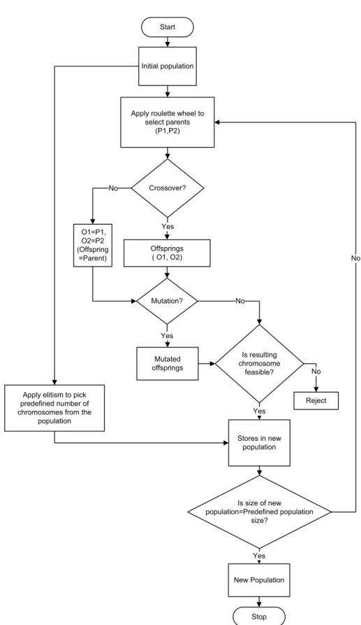
3.1.1 GA Initialization . . . 43
3.1.2 GA Operators . . . 45
3.1.3 GA Iteration Loop . . . 49
3.2 Modeling of Embedded Constraints . . . 50
3.2.1 Cutting Force, Power and Torque . . . 50
3.2.2 Stability of the Milling Process . . . 53
3.2.3 Cutting Tool Bending Stress . . . 61
3.2.4 Deflection of Cutting Tool . . . 62
3.2.5 Clamping Load Limits . . . 63
3.3 Use Case 1: Optimization System for Pocket Milling with One-Way Toolpath . . 64
3.4 Use Case 2: Optimization System for Prismatic Part . . . 67
3.4.1 Pre-Module for Geometrical Information . . . 68
3.4.2 Detailed Steps of the Algorithm . . . 71
3.5 Use Case 3: Optimization System for Pocket Milling with Smooth and Constant Engagement Toolpaths . . . 72
3.5.1 Smooth and Constant Engagement Toolpath Generation . . . 74
3.5.2 Optimal Selection of Cutting Conditions and Toolpaths . . . 77
3.6 Conclusion . . . 78
4 Implementation and Experimental Validation of the Optimization System 81 4.1 Implementation of Optimization Use Case 1 . . . 81
4.1.1 Definition of Various Inputs . . . 81
4.1.2 Tuning of the Optimization System . . . 83
4.1.3 Results of the Simulation . . . 83
4.2 Implementation of Optimization Use Case 2 . . . 87
4.2.1 Definition of Various Inputs . . . 87
4.2.2 Results of the Simulation . . . 89
4.2.3 Reduction in Machining Time . . . 89
4.3 Implementation of Optimization Use Case 3 . . . 91
4.3.1 Definition of Various Inputs . . . 91
4.3.2 Results of the Simulation . . . 91
4.4 Experiment Setup . . . 97
Contents
4.4.2 FRF Measurement . . . 98
4.4.3 Cutting Sound Measurement . . . 99
4.4.4 Cutting Force Measurement . . . 100
4.4.5 Cutting Power Measurement . . . 101
4.5 Validation of Optimization Use Case 1 . . . 101
4.6 Validation of Optimization Use Case 2 . . . 102
4.6.1 Energy Saving . . . 103
4.7 Validation of Optimization Use Case 3 . . . 106
4.7.1 Toolpath Verification . . . 108
4.8 Conclusion . . . 108
5 Indirect Identification of Tangential Force Coefficient 111 5.1 Introduction . . . 111
5.2 Theoretical Model for Total Spindle Power Calculation . . . 114
5.2.1 Mechanical Losses in a Motorized Spindle . . . 115
5.2.2 Electrical Losses in a Motorized Spindle . . . 115
5.2.3 Model Synthesis . . . 115
5.3 Development of an Empirical Model for Cutting Torque Prediction . . . 117
5.4 Validation and Implementation of the Developed Cutting Torque Model . . . . 121
5.5 Conclusion . . . 124
6 FRF Prediction by Receptance Coupling 125 6.1 Introduction . . . 125
6.2 Receptance Coupling with Joint Dynamics . . . 126
6.2.1 Inverse Receptance Coupling . . . 129
6.3 Beam Receptance . . . 131
6.3.1 Euler–Bernoulli Beam Theory . . . 132
6.3.2 Timoshenko Beam Theory . . . 135
6.3.3 Beam Modeling using FEM . . . 138
6.3.4 Comparison of Beam Theories . . . 142
6.3.5 Modeling of Fluted End Mill . . . 143
6.4 Implementation and Experimental Validation . . . 144
6.5 Conclusion . . . 147
7 Online Chatter Detection and Control 149 7.1 Introduction . . . 149
7.2 Chatter Detection and Control System . . . 149
7.2.1 Frequency Domain Analysis of Cutting Sound Signal . . . 150
7.2.2 Chatter Detection System . . . 153
7.2.3 Chatter Control System . . . 158
7.3 Experimental Results and Discussion . . . 158
7.3.1 Results with Face Mill . . . 159
7.3.3 Verification of Corrected Spindle Speed . . . 170
7.4 Conclusion . . . 172
8 Conclusion 173 8.1 Summary of the Research Work . . . 173
8.1.1 Main Contributions of the Research Work . . . 177
8.2 Recommendations for Future Work . . . 177
Bibliography 186 A Cutting Force Modeling 187 A.1 Analytical Modeling of Milling Force . . . 187
A.1.1 Validation of the Prediction Model . . . 189
B Force Coefficients Identification 191 B.1 Experimental Details . . . 191
B.2 Force Coefficients Results . . . 192
C FRF Measurement 195 D Stability Limit Modeling 197 D.1 Chatter Stability Theory . . . 200
E Improvements in Toolpath Generation Algorithm 205 F Detailed Literature Review: Online Chatter Detection 207 F.1 Introduction . . . 207
F.1.1 Requirement for Chatter Detection Sensors . . . 208
F.2 Literature Review of Chatter Detection Sensors . . . 209
F.2.1 Limitations of the Sensors . . . 211
F.3 Literature Review of Chatter Recognition Techniques . . . 213
F.3.1 Threshold Level . . . 213
F.3.2 Statistical Detection . . . 214
F.3.3 Frequency Domain Analysis . . . 215
G Stability Analysis of Flexible Workpiece 217 G.1 Introduction . . . 217
G.2 Stability Analysis during Single Milling Pass . . . 218
G.3 Change in the Dynamics of Thin-Walled Workpiece . . . 223
G.4 Conclusion . . . 225
List of Figures
1.1 Definition of high speed milling . . . 2
1.2 Steps involved in part programming . . . 3
1.3 Definition of cutting conditions . . . 4
1.4 Industrial development of part programs . . . 5
1.5 System architecture of OptMill system . . . 9
2.1 Geometry of different end mills . . . 12
2.2 Geometrical representation of the milling process . . . 13
2.3 Complete milling system . . . 17
2.4 Flexible machine tool system . . . 18
2.5 Effect of phase difference on the chip thickness . . . 18
2.6 Principal research lines for chatter . . . 19
2.7 Stability lobe diagram . . . 20
2.8 General layout of FRF measurement system . . . 21
2.9 Offline strategies for chatter . . . 23
2.10 FRF measurement by hammer testing . . . 24
2.11 Experimental setup for measurement of speed dependent FRF . . . 25
2.12 SLD with speed dependent FRF . . . 25
2.13 System with translational and rotational springs, and dampers . . . 26
2.14 Stability analysis of flexible workpiece dynamic . . . 27
2.15 Dynamic coupling of machine tool system and workpiece . . . 28
2.16 Concept of experimental generation of SLD . . . 32
2.17 Experimentally developed SLD on the workpiece . . . 33
2.18 Minimization of number of cutting passes . . . 35
2.19 Toolpath routines for pocket milling . . . 36
2.20 Different engagement conditions . . . 37
3.1 Binary-coded string (chromosome structure) . . . 44
3.2 Algorithm to generate the initial population . . . 46
3.3 Algorithm to generate new population from the previous population . . . 47
3.4 Roulette wheel as reproduction operator . . . 48
3.5 Crossover operator . . . 48
3.7 Algorithm for iteration loop for GA analysis . . . 49
3.8 Module for analytical cutting force modeling . . . 50
3.9 Geometry of a helical end mill . . . 51
3.10 Chip formation phenomenon in milling operation . . . 51
3.11 Different milling modes . . . 53
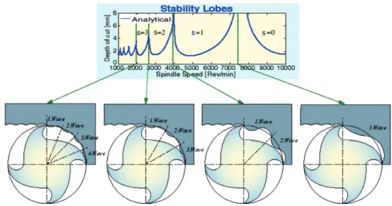
3.12 Stability peaks corresponds to integer number of waves between tooth periods in milling . . . 55
3.13 Presentation of different spindle speed at different lobe numbers . . . 56
3.14 SLD (Apandn) validation . . . 57
3.15 SLD (Aeandn) validation . . . 59
3.16 SLD (AeandAp) validation . . . 60
3.17 Chatter free limits for different machine axes . . . 61
3.18 Bending moment acting on the cutting tool . . . 62
3.19 Pocket with one-way toolpaths . . . 64
3.20 System architecture of pocket milling with one-way toolpath . . . 66
3.21 Pre-module for geometrical information extraction . . . 68
3.22 Toolpath extraction from the APT file . . . 69
3.23 Engagement angle calculation . . . 71
3.24 System architecture for pocket milling with smooth and constant engagement toolpaths . . . 73
3.25 Presentation of sign distance functions . . . 74
3.26 Concept of constant engagement toolpath generation . . . 75
3.27 Smooth and constant engagement toolpaths . . . 76
3.28 Concept of corner looping . . . 76
4.1 Experimentally measured frequency response function . . . 82
4.2 Effect of GA parameters on machining time . . . 85
4.3 Convergence of cutting conditions . . . 86
4.4 Toolpath for pocket milling . . . 87
4.5 Engagement angle for pocket . . . 88
4.6 Engagement angle for contouring . . . 88
4.7 Experimentally measured frequency response function . . . 89
4.8 Convergence of cutting conditions for pocket . . . 90
4.9 Dimensions of the pocket used for validation . . . 91
4.10 Toolpath at different stepover values . . . 93
4.11 Toolpath length and computation time at different stepover . . . 94
4.12 Convergence of cutting conditions for pocket milling . . . 95
4.13 Complete constant engagement and smooth toolpath for pocket milling . . . . 96
4.14 Overall experimental setup for validation . . . 97
4.15 Experimental setup: mounting of sensors and data acquisition system . . . 98
4.16 C.B. Ferrari A152 machine tool . . . 99
List of Figures
4.18 Shure microphone PG81 . . . 100
4.19 Multi-component piezoelectric dynamometer, Kistler 9255B . . . 100
4.20 Power cell PPC-3 . . . 101
4.21 Verification of cutting conditions for optimization use case 1 . . . 102
4.22 Signals collected during one axial level . . . 103
4.23 Verification of cutting conditions for optimization use case 2 . . . 104
4.24 Details of deep pocket milling . . . 104
4.25 Measured total power during complete milling . . . 105
4.26 Measured total power during one axial pass . . . 106
4.27 Signals collected during one axial level . . . 107
4.28 Verification of cutting conditions for optimization use case 3 . . . 107
4.29 Contour parallel and constant engagement toolpath . . . 108
4.30 Experimental results for toolpath comparison . . . 109
5.1 Effect ofKt candKr con stable limits . . . 112
5.2 Effect ofKt candKr con resultant cutting force and power . . . 113
5.3 Overall experimental setup . . . 117
5.4 Experimental setup: mounting of torque dynamometer and data acquisition platform . . . 118
5.5 Air cutting experimental results . . . 119
5.6 Illustration of the dependency of total power loss . . . 120
5.7 Slot cutting experimental results . . . 121
5.8 Average values of the cutting torque . . . 122
6.1 Spindle/tool holder/end mill system . . . 126
6.2 Degrees of freedom of end mill and spindle/tool holder . . . 128
6.3 Experimental measurement ofhB22f f . . . 130
6.4 Inverse receptance coupling . . . 130
6.5 Bode plots using Euler–Bernoulli beam theory . . . 133
6.6 Bode plots using Euler–Bernoulli beam theory . . . 134
6.7 Bode plots using Timoshenko beam theory . . . 137
6.8 Bode plots using Timoshenko beam theory . . . 138
6.9 Finite element model of beam . . . 139
6.10 Sample of “eig” file . . . 140
6.11 System for FRF prediction using ANSYS . . . 140
6.12 Bode plots using ANSYS . . . 141
6.13 Bode plots using ANSYS . . . 142
6.14 Comparison of natural frequencies . . . 143
6.15 Experimental setup for measurement of FRFs . . . 144
6.16 Measured FRFs for inverse RC . . . 145
6.17 Experimental details for predicted and measured FRFs . . . 146
6.18 Predicted and measured FRFs for end mills . . . 146
7.1 Overall architecture of chatter detection and control system . . . 150
7.2 Concept of FFT plot . . . 152
7.3 Cutting sound signal and spindle speed signal . . . 154
7.4 Complete FFT spectrum . . . 155
7.5 FFT spectrum for 100-1000Hz . . . 156
7.6 Approach for automatic peak detection . . . 157
7.7 Approach for dominant chatter peak detection . . . 157
7.8 Results of cutting test (Ap=1.3mm), stable milling . . . 160
7.9 Results of cutting test (Ap=1.4mm), stable milling . . . 161
7.10 Results of cutting test (Ap=1.7mm), chatter . . . 162
7.11 Results of cutting test (Ap=1.5mm), chatter . . . 163
7.12 Results of cutting test (Ap=1.5mm andn=19500rpm), stable milling . . . 164
7.13 Results of cutting test (Ap=7.5mm andn=24000rpm), stable milling . . . 164
7.14 Results of cutting test (Ap=8mm), stable milling . . . 165
7.15 Results of cutting test (Ap=10mm), chatter . . . 166
7.16 Finished surface of the workpiece . . . 167
7.17 Results of cutting test (Ap=9.5mm), chatter . . . 168
7.18 Results of cutting test (Ap=12mm), severe chatter . . . 169
7.19 Results of cutting test (Ap=10mm andn=7150rpm), stable milling . . . 170
7.20 Results of cutting test (Ap=10mm andn=7500rpm), stable milling . . . 171
A.1 Validation of milling forces . . . 190
B.1 Setup for dynamic calibration of dynamometer . . . 192
B.2 Magnitude and phase of the dynamic response . . . 193
B.3 Average cutting forces . . . 193
C.1 Details of experimental setup for FRF measurement . . . 195
D.1 Flexible machine tool system . . . 197
D.2 Dynamic chip thickness . . . 198
E.1 Different cases to detect intersection in toolpath generation algorithm . . . 206
F.1 Setup for chatter detection system . . . 210
F.2 Transfer function of the table type dynamometer . . . 211
F.3 Threshold method to detect chatter . . . 214
F.4 Chatter detection using statistical method . . . 215
G.1 Finite element modeling of flexible workpiece . . . 218
G.2 Mode shapes of the flexible workpiece . . . 219
G.3 FRF computation by FEM . . . 219
G.4 FRFs at different contact points of cutting tool with workpiece . . . 220
List of Figures
G.6 Comparison of FRFs of machine tool, workpiece and coupled system . . . 221
G.7 FRFs of the coupled system at different contact points . . . 222
G.8 3D stability lobe diagram . . . 222
G.9 Stability lobe diagram for coupled system . . . 223
G.10 Different stages of milling of flexible workpiece . . . 224
G.11 Change in workpiece dynamics . . . 225
List of Tables
3.1 Inputs for validation of SLD (Apandn) . . . 57
3.2 Inputs for validation of SLD (Aeandn) . . . 58
3.3 Inputs for validation of SLD (AeandAp) . . . 59
4.1 Specifications of the cutting tool (16mm end mill) . . . 81 4.2 Cutting force coefficients . . . 82 4.3 Optimal cutting conditions for different pockets . . . 84 4.4 Specifications of the cutting tool (20mm end mill) . . . 87 4.5 Cutting force coefficients . . . 88 4.6 Reduction in machine time . . . 90 4.7 Cutting conditions for deep pocket . . . 105 4.8 Reduction in machining time and total energy . . . 106 5.1 Effect of tangential cutting force coefficients on stable limits . . . 112 5.2 Power loss components in a motorized spindle drive . . . 116 5.3 Tangential force coefficients identified from the measured and the predicted
cutting torque . . . 123 6.1 Properties of the beam section . . . 132 6.2 Effect of mesh size on the natural frequencies . . . 139 6.3 Comparison of natural frequencies . . . 143 6.4 Area section properties for fluted end mills . . . 143 7.1 Details of experiments for validation of chatter detection and control system . 159 7.2 Cutting conditions selected for experiments . . . 159 A.1 Input parameters for validation of cutting force modeling . . . 189 B.1 Slot milling experiments . . . 191 B.2 Cutting force coefficients . . . 193 G.1 Material properties of the workpiece . . . 218 G.2 Natural frequencies of modes of different cases . . . 223
List of Abbrevations
Fx Average cutting force in feed directionFy Average cutting force in normal to feed direction Fz Average cutting force in axial direction
ωm Angular speed of spindle
φ Immersion angle
φex Exit angle from the cutting zone
φst Start angle in the cutting zone Ae Radial depth of cut inmm Ap Axial depth of cut inmm D Diameter of the end mill inmm Dp Depth of the pocket inmm Fa Axial cutting force inN Fr Radial cutting force inN Ft Tangential cutting force inN
ft Feed rate inmm/rev-flute
Fx Cutting force in feed direction inN
Fy Cutting force in normal to feed direction inN Fz Cutting force in axial direction inN
I Spindle motor current inA
Kac Cutting force coefficient in axial directionN/mm2 Kae Edge force coefficient in axial directionN/mm
kl m Load meter constant
Kr c Cutting force coefficient in radial directionN/mm2 Kr e Edge force coefficient in radial directionN/mm
Kt c Cutting force coefficient in tangential directionN/mm2 Kt e Edge force coefficient in tangential directionN/mm Lp Length of the pocket inmm
N Number of flutes of the cutting tool
n Spindle speed inrpm
PAC e f f Effective power inW
U Spindle motor voltage
Wp Width of the pocket inmm
AE Acoustic Emission
APT Automatically Programmed Tool CAD Computer-Aided Design
CAM Computer-Aided Manufacturing ChatFree Chatter Free
CL Cutter Location
CNC Computerized Numerical Control DFT Discrete Fourier Transform FEA Finite Element Analysis FFT Fast Fourier Transform
FRF Frequency Response Function FT Fourier Transform
HSM High Speed Milling/Machining IRC Inverse Receptance Coupling LDV Laser Doppler Vibrometer MDOF Multi-Degree-of-Freedom
List of Abbrevations
NC Numerical Control noap Number of Axial Passes nop Number of Passes norp Number of Radial Passes RC Receptance Coupling
RCSA Receptance Coupling Substructure Analysis SF Spindle Frequency inHz
SLD Stability Lobe Diagram
STEP STandard for the Exchange of Product model data TPF Tooth Passing Frequency inHz
1
Introduction
1.1 Background
The desired shapes of most mechanical parts are accomplished by various machining op-erations. Material removal processes are still the most widely used machining processes to manufacture the final product though there is a significant development in the manufac-turing domain (Quintana, 2009). A blank is converted into the final product by removing extra material by turning, drilling and milling followed by special operations such as boring, broaching and grinding (Altintas, 2000). Among different types of material removal processes, milling holds a dominant position in the manufacturing practices due to its wide range of industrial applications (Held, 1991b). In milling, a rotating cylindrical cutting tool removes the material along a predefined toolpath to achieve the desired shape of final workpiece. Often large amounts of material are removed from the blank during milling operations (Faassen, 2007).
In the manufacturing of automotive and aerospace parts, mold and die, 2.5D (or 2.5-axis) milling is very important (Hatna et al., 1998; Tekeli and Budak, 2005). Often in industrial practice even complicated parts are machined from a blank first by 2.5D rough milling fol-lowed by 3D-5D finishing operations (Lee and Chang, 1995). 2.5D milling is able to perform point-to-point, contouring and pocketing operations. More than 80% of all mechanical parts to be machined can be manufactured by only pocket milling: the removal of material within a defined boundary (Held, 1991a; Lambregts et al., 1996). Most modern production floors are equipped with high speed CNC (computer numeric control) machine tools and advanced CAD/CAM (computer-aided design/manufacturing) software to enhance the speed and accu-racy of the overall machining process.
1.1.1 High Speed Milling
High speed milling (HSM) is able to achieve high material removal rates at higher spindle speeds and feed rates. HSM has become an indispensable process in modern manufacturing
10 100 1000 10000 Nickel-Base Alloys Titanium Steel Cast Iron Alumminium Bronze, Brass Fiber Reinforced Plastics HSM range Transition range Normal range
Cutting Speed (m/min)
Figure 1.1: Definition of high speed milling (Schulz and Moriwaki, 1992)
industry due to its high productivity and reliability. Even though HSM has been known for a long time, authors have not established its clear and concise definition. A comprehensive sum-mary of these definitions is given by (Agba et al., 1999; Quintana, 2009). The few definitions, which are mainly encountered in the literature, are highlighted below:
• Spindle designers define HSM as spindles withD Nnumbers of 500,000 to 1,500,000. TheD Nnumber is the product of the spindle diameter in mm with spindle speed in rpm.
• Based on the peripheral speed of the cutting tool, cutting speeds of 1500ft/min (∼7.6m/s) or more are considered as high speed machining.
• High speed milling generally refers to end milling or ball nose end milling at high rotational speeds (10,000-1,00,000rpm) (Urbanski et al., 2000).
• The term “high speed milling” is generally used to describe end milling with small diameter cutting tools (≤10mm) at high rotational speeds (≥10, 000rpm) (Toh, 2005). • High speed milling is defined based on the workpiece material and corresponding
cutting speed as shown in Figure 1.1 (Schulz and Moriwaki, 1992).
• Smith and Tlusty defined HSM based on spindle and cutting tool dynamics (Smith and Tlusty, 1997). HSM occurs whenever the tooth passing frequency (TPF) can approach a substantial fraction of the dominant (most flexible) natural frequency of the machine tool system. TPF is defined as:
TPF=N n
60 (1.1)
1.1. Background
Geometrical Model
Toolpath Definition and Data Processing CAD/CAM Interface Toolpath Strategy Cutting Conditions Post Processing CNC Machine Geometry Files APT/CL File NC Program Machined Workpiece
Figure 1.2: Steps involved in part programming
1.1.2 NC Part Programming
Modern CAM systems facilitate the generation of part programs from geometrical models created in a CAD environment. Part programs are sets of numerical commands to guide the CNC machine tools to follow a predefined sequence of machining operations at predetermined speeds necessary to produce a workpiece of desired shape and dimensions. Several CAD/CAM systems are available in the modern manufacturing industry. The main steps involved in NC part programming, as presented in Figure 1.2, are summarized below:
(i) The part programmer1can create the geometrical model of the desired part in the CAM package or directly import it from CAD system.
(ii) After the geometric modeling, the machine datum, part boundaries, cutting tool, ap-proach/retract planes and other operational parameters are defined. The CAM system requires geometrical parameters namely axial and radial depth of cut to compute the toolpath trajectory. Spindle speed and feed rate are also needed to define the movement
1In industrial practice, toolpath trajectory and cutting conditions are selected by the user. Depending upon the size of the manufacturing unit, user can be a part programmer or a machine operator. In large manufacturing units often the NC part programs are prepared by a part programmer and the actual machining is performed by a machine operator. In small production floors the same person acts both as a part programmer and a machine operator.
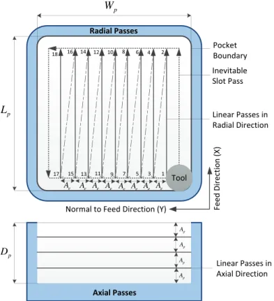
of a cutting tool along the toolpath trajectory. The cutting conditions, namely spindle speed, feed rate, axial depth of cut and radial depth of cut, are represented in Figure 1.3.
Spindle speed Feed rate Axial depth ofcut Radial depth ofcut Feed direction (X) Cutting tool Workpiece Normal to feed direction (Y)
Figure 1.3: Definition of cutting conditions: spindle speed (n), feed rate (ft), radial depth of
cut (Ae) and axial depth of cut (Ap)
(iii) The computer will process the input data to generate the toolpaths and corresponding APT (automatically programmed tool) or CL (cutter location) file.
(iv) Post processing is required to convert the general instructions from APT file to machine specific NC codes. A post processor is computer software which converts the cutting tool movement into a format which the machine controller can interpret correctly. These NC part programs are then transferred to a CNC machine tool for actual machining.
The performance of the developed NC part program, which is directly dependent on the selection of cutting conditions and toolpath, is the driving factor for the overall productivity of the complete milling process.
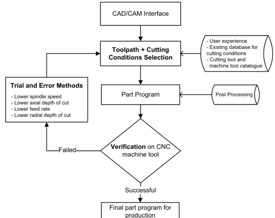
1.2 Motivation
In spite of many advances in CNC machine tools and CAD/CAM software, an industrial part programmer must adhere to the procedure (as shown in Figure 1.4) to finalize the part program to manufacture the final workpiece.
For a given machine tool/spindle/tool holder/cutting tool and workpiece system, the physical phenomena that occur due to the interaction between machine tool and workpiece system during the milling process depend significantly on the choice of cutting conditions. Cutting conditions have complex non-linear relationships with different physical phenomena (Bal-achandran, 2001; Wiercigroch and Budak, 2001; Altintas and Weck, 2004). Current CAD/CAM
1.2. Motivation CAD/CAM Interface Part Program Verificationon CNC machine tool Failed - User experience - Existing database for cutting conditions - Cutting tool and
machine tool catalogue
Final part program for production Successful
Trial and Error Methods
Toolpath + Cutting Conditions Selection
- Lower spindle speed - Lower axial depth of cut - Lower feed rate - Lower radial depth of cut
Post Processing
Figure 1.4: Industrial development of part programs
packages do not provide any guidance for selection of cutting conditions due to the unavail-ability of milling process modeling and corresponding input parameters. The selection of cutting conditions relies solely on part programmer experience, handbook guidelines or speci-fications provided in catalogues of cutting tools and machine tools (Rai, 2008; Shunmugam et al., 2000). Even the experienced user cannot ensure the right selection of cutting conditions as physical phenomena change significantly with every new variant of machine tool/spindle/-tool holder/cutting tool/spindle/-tool and workpiece system. Moreover, tool/spindle/-toolpath generation by current CAD/CAM packages is purely geometric in nature and results in changes in radial depth of cut along the toolpath (Kramer, 1992). Poor selection of cutting conditions and toolpath at the part programming stage leads to the following problems during actual machining:
• Machine tool and workpiece system vibrations, also known as chatter vibrations, are encountered frequently. Chatter vibrations occur due to the dynamic interaction of the machine tool system and workpiece (Altintas and Budak, 1995; Quintana, 2009). Chatter is the most undesirable and complex phenomenon which leads to unavoidable consequences during any machining process. During rough milling the dynamics of the machine tool system are more dominant but in the milling of thin-walled parts, work-piece system dynamics become significant (Bravo et al., 2005; Davies and Balachandran, 2000).
• Wrong selection of cutting conditions leads to high magnitude of cutting forces. More-over, the variation of radial depth of cut along the generated toolpath causes high fluctuations of cutting forces along the toolpath (Tandon et al., 2002; Dhanik, 2009). • Selected cutting conditions often violate the available limits of cutting power,cutting
torque or feed rate of the machine tool (Altintas, 2000).
• Excessive wear and/or breakage of the cutting tool (Byrne et al., 1995).
These problems lead to poor surface finish, workpiece damage, violation of tolerance limits, additional cost, unwanted waste and reduction in the machine tool spindle working life. In order to overcome these problems, part program needs to be verified iteratively using trial and error experiments and often conservative cutting conditions are selected. This procedure leads to long preparation time of part programs and lower machining performance which thus lowers significantly overall productivity (Hatna et al., 1998). Moreover, machine tool capabilities are not fully utilized due to the selection of conservative cutting conditions. The competitive economic environment has brought new challenges to the manufacturing industry. Significant reduction in machining time and production cost, and improvement in overall productivity have become an ultimate requirement. For a given machine tool/spindle/-tool holder/cutting tool/spindle/-tool and workpiece system, the main objective of the part programmer is to select chatter free cutting conditions with lower cutting forces while respecting the power and torque limits of machine tools and other practical constraints of milling system. There-fore, right and optimal selection of cutting conditions is of great concern for manufacturing industry (Wang et al., 2004; Rai et al., 2009). Smooth toolpaths with minimum variation of radial depth of cut along the cutting path have apparent improvements over the toolpaths generated by current CAD/CAM systems for high speed milling (Dhanik, 2009). In order to satisfy the pressing need of modern manufacturing, a system must be developed to ensure the optimal selection of cutting conditions and toolpath while respecting the limits of various physical phenomena occurring during high speed milling.
The goal of achieving high material removal rates is often hampered by chatter vibration and high cutting forces. Chatter and high cutting forces affect significantly the surface quality, permissible tolerance limits and working life of spindle and cutting tools. Several authors have developed mathematical models to predict accurately the chatter free cutting conditions and cutting forces. The following barriers are often encountered for their complete implementation at production floors:
(1) For prediction of chatter free cutting conditions by mathematical modeling, dynamic characteristics of machine tool/spindle/tool holder/cutting tool combination are required (Altintas and Budak, 1995; Solis et al., 2004). The dynamic characteristics, in terms of frequency response functions (FRF), are identified experimentally for every new variant of machine tool/spindle/tool holder/cutting tool system. To avoid a large number of
exper-1.3. Research Objectives
iments, an enhanced modeling procedure can be implemented to predict the dynamic characteristics of different variants (Schmitz and Burns, 2003; Park et al., 2003).
(2) Force coefficients are an important input for mathematical models to predict cutting forces and chatter free cutting conditions (Budak et al., 1996; Altintas and Budak, 1995). These force coefficients are identified experimentally (with the use of cutting force dynamometer) for a given cutting tool geometry and workpiece material (Budak and Altintas, 1994). This experimental setup is quite costly and even not practical for implementation in industrial environments. Development of a simple and enhanced methodology is thus required to facilitate the identification of force coefficients on production floors.
Chatter is the most complex and widely studied topic in machining research. Many studies have been executed to understand, detect, avoid, prevent, reduce or suppress chatter vibration (Altintas and Weck, 2004; Budak, 2006b; Quintana and Ciurana, 2011). These research studies require costly experimental setups, complex mathematical modeling or prior knowledge of dynamic characteristics to target chatter vibration. Mathematical modeling to predict chatter free cutting conditions is a complex task due to the multi-degree-of-freedom (MDOF) system, multiple cutting flutes, variable cutting forces and chip load directions (Balachandran, 2001). Though developed mathematical models predict accurately the chatter free cutting conditions their implementation in production floors has not yet been achieved due to absence of technical expertise and experimental resources. There is still a practical need to bring to the production floors an inexpensive, easy to use and computationally fast system that can automatically detect chatter vibration during milling and thereafter propose a control strategy to the machine operator. This will be a considerable step towards achieving the goal of smart machining.
Apart from many challenges discussed above, milling of thin-walled workpiece is also a concern due to its changing dynamics along a toolpath which further makes the selection of chatter free cutting conditions a difficult task (Thevenot et al., 2006a; Davies and Balachandran, 2000). Change in workpiece dynamics can be studied with experimental modal analysis or using numerical tools like finite element analysis (FEA). FEA facilitates investigation of the workpiece dynamic behavior even at the part programming stage when the actual workpiece does not exist. The development of an enhanced procedure using FEA will surely guide the part programmer to select chatter free cutting conditions for milling of thin-walled workpieces.
1.3 Research Objectives
In order to address the challenges and requirements stated in the previous section, the follow-ing main objectives are defined for this research work:
1. To develop a genetic algorithm (GA) based optimization system for the optimal selection of cutting conditions and/or toolpath at the part programming stage while respecting
the practical constraints of the machine tool and workpiece system. Implementation of the developed optimization system for the different use cases:
(i) For a given pocket dimensions and material, and machine tool/spindle/tool hold-er/cutting tool system, minimization of pocketing time with one-way toolpaths by optimal selection of cutting conditions. Implementation and experimental validation of this use case of milling systems.
(ii) For a given multi-feature prismatic part general toolpaths, minimization of ma-chining time by optimal selection of cutting conditions. Implementation and experimental validation of this use case of milling systems.
(iii) For a given pocket, minimization of pocket milling time by optimal selection of cutting conditions and corresponding smooth and constant stepover toolpath. Implementation and experimental validation of this use case of milling systems. 2. Development of a procedure for prediction of machine tool system FRFs for different
end mills. Implementation and experimental validation of predicted FRFs.
3. To develop an enhanced methodology for the indirect identification of tangential force coefficients from the spindle motor current. Implementation and experimental valida-tion of the proposed methodology.
4. Development of an online chatter detection and control system in order to detect automatically the existence of chatter vibrations and propose a control strategy. Imple-mentation and experimental validation of the developed system.
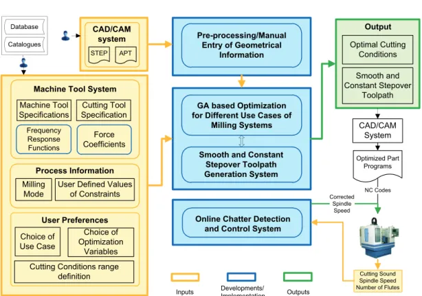
1.4 System Architecture
The overall architecture of the developed system2with various inputs, developments and corresponding outputs for the research work is presented in Figure 1.5. Different developed subsystems, with their corresponding inputs, are combined to achieve different objectives of 2.5D high speed milling. The overall architecture is explained briefly in a generalized way with various developments and their inputs and corresponding outputs:
• The workpiece geometrical and part programming information is pre-processed from the corresponding inputs with the following developments:
– Feature boundary and depth is extracted from the STEP file of a geometrical model created in the CAD system. Feature boundary and depth for the simple shaped features can also be entered manually.
– The part programming information, in terms of toolpath trajectory with linear and circular segments, is extracted from the APT file generated from a CAM system.
1.4. System Architecture Cutting Tool Specification Machine Tool Specifications Frequency Response Functions Force Coefficients Database GA based Optimization for Different Use Cases of
Milling Systems CAD/CAM
System Optimal Cutting Conditions Smooth and Constant Stepover Toolpath Output Milling Mode
User Defined Values of Constraints
Optimized Part Programs
NC Codes
Machine Tool System
Process Information Pre-processing/Manual Entry of Geometrical Information Developments/ Implementation Outputs Inputs Catalogues Choice of Use Case Choice of Optimization Variables STEP CAD/CAM system APT
Online Chatter Detection and Control System
Corrected Spindle
Speed
User Preferences
Cutting Conditions range definition
Smooth and Constant Stepover Toolpath Generation System
Cutting Sound Spindle Speed Number of Flutes
Figure 1.5: System architecture of OptMill system
– The pre-processed geometrical and part programming information is used for the calculation of engagement angles along the toolpath.
The geometrical and part programming information of the workpiece is used as an input to the developed system for different use cases of milling system.
• A GA based optimization system (Chapter 3) is developed for selection of cutting con-ditions and/or toolpaths for high speed milling. The system includes inputs from the machine tool and workpiece system, process related information and user prefer-ences. Operational constraints of the machine tool, such as available cutting power and torque, chatter vibration limits due to the dynamic interaction between cutting tool and workpiece, acceptable limits of bending stress and deflection of the cutting tool and clamping load limits of the workpiece system are embedded in the optimization system (Section 3.2). Various submodules of the GA based optimization are developed in a generic way. The following three different use cases are targeted with the developed optimization system:
– For given pocket dimensions, pocketing time with one-way toolpaths is minimized by optimal selection of spindle speed, feed rate, axial and radial depths of cut. The user has also the possibility of fixing one of the optimization variables based on the requirements and application (Section 3.3).
time for each feature is minimized by optimal selection of spindle speed, feed rate and axial depth of cut. During this use case, radial depth of cut is kept constant (Section 3.4).
– For given pocket dimensions and other set of inputs, pocketing time is minimized by optimal selection of all the cutting conditions and corresponding smooth and constant stepover toolpath (Section 3.5).
The developed optimization system is implemented for the optimal selection of cutting conditions and/or toolpath for different workpieces and is also verified experimentally (Chapter 4).
• In order to increase the scope of the overall system, the following enhanced methods and procedures are developed to identify the important inputs for the OptMill system:
– An enhanced methodology is presented for the indirect identification of tangential force coefficients from the spindle motor current. The methodology includes the development of an empirical model for cutting torque prediction from spindle motor current with the implementation of spindle power model that accounts for all mechanical and electrical power losses (Chapter 5).
– Dynamic characteristics of each variant of machine tool/spindle/tool holder/end mill, in terms of FRF, is required to predict chatter free limits accurately. FRFs are often measured with hammer testing experiments. In order to avoid the te-dious tests, an enhanced procedure using the receptance coupling technique is implemented to predict the FRF of a machine tool/spindle/tool holder/cutting tool system for different cutting tools (Chapter 6).
• An online chatter detection and control system is developed. The system is able to detect the existence of chatter vibration in the case of unstable milling and proposes an alternative spindle speed to realize stable milling. The developed system can also be used as an independent system on production floors (Chapter 7).
• Apart from the many developments discussed above, an enhanced numerical procedure is developed for the selection of chatter free cutting conditions while considering the change in workpiece dynamics using finite element analysis (Appendix G).
2
State-of-the-Art
2.1 Cutting Force during Milling
Cutting force during milling is one the most significant process parameters. High cutting forces cause cutting tool and workpiece deflections which may result in violation of permissible tolerances (Budak, 2006a). Moreover, high cutting forces have an adverse effect on the working life of cutting tools and thus affect significantly the overall productivity of the milling process. Accurate prediction of cutting forces helps to calculate the required cutting power and torque from the machine tool, to control tolerance limits and to improve the working life of the cutting tool. In this section a brief introduction to the geometry of the cutting tool and cutting force modeling is presented.
A milling process consists of an end mill (or cutting tool) that has multiple cutting flutes on both its periphery and its tip which allows end cutting and peripheral cutting. The envelop or outer geometry of the general cutting tool is defined by seven geometrical parameters (D,R,Rr,Rr,α,β,h) as presented in Figure 2.1a. Shapes of the different end mills used in
industry can be realized from the geometrical parameters as shown in Figure 2.1b. Simple cylindrical helical end mills are used in the milling of prismatic parts, bull nosed end mills produce parts with bottom floors with fillets, tapered helical end mills are used in five axis machining of jet engine compressors, and form cutting tools are used to mill complex pro-files such as turbine blade carrier rings. A helical cutting edge is wrapped around the outer geometry of the end mill as shown in Figure 2.1c. Cutting point (P) along the cutting edge trajectory for different helical end mills is shown in Figure 2.1d. The accurate identification of the coordinates of cutting point (P) along the cutting edge plays a vital role in the mechanics of cutting (Engin and Altintas, 2001).
For the prediction of cutting forces, the cutting edge is assumed to be a sequence of infinitesi-mal single point cutting edge segments. The differential tangential (d Ft), radial (d Fr) and axial
(d Fa) cutting forces (as shown in Figure 2.1c) are computed for every cutting edge segment
(a) General cutting tool geometry (b) Shape of the different end mills
(c) Cutting edge of the general end mill (d) Helical cutting edge of different end mills
Figure 2.1: Geometry of different end mills (Engin and Altintas, 2001)
on the infinitesimal cutting edge segment are given by:
d Ft(φ)= Kt ch(φ)+Kt e d z d Fr(φ)=Kr ch(φ)+Kr ed z d Fa(φ)= Kach(φ)+Kae d z (2.1)
2.1. Cutting Force during Milling
where,Kt c,Kr c andKac are the cutting force coefficients contributed by shearing action
andKt e,Kr eandKaeare the edge force coefficients in tangential, radial and axial directions
respectively. Force coefficients are the parameters which represent the combined property of the cutting tool geometry and workpiece material.d zis the edge contact length.h(φ) is the uncut chip thickness normal to the cutting edge which varies with the position of cutting point (P) and the immersion angle (as shown in Figure 2.2). Chip thickness is expressed as:
h(φ)=ftsinφ (2.2)
where,ftis the feed rate in mm/rev-flute andφis the time varying immersion angle. Cutting
forces in feed (d Fx), normal to feed (d Fy) and axial (d Fz) directions are presented in the form
of differential cutting forces (Equation 2.1) as (Altintas, 2000):
d Fx(φ)= −d Ftcosφ−d Frsinφ d Fy(φ)=d Ftsinφ−d Frcosφ d Fz(φ)=d Fa
(2.3)
Cutting forces are modeled for given cutting tool geometry, cutting conditions and workpiece
st I ex I j I ( ) x F I t
F
feed n e A t f X rF
Chip load Workpiece End Mill Workpiece ( ) y F I n fee dFigure 2.2: Geometrical representation of the milling process, redrawn from (Altintas, 2000) material. There are two different force analysis models: mechanics of cutting model and mechanistic models. These models are differentiated based on the identification of force coefficients.
2.1.1 Mechanics of Cutting Model
In the mechanics of cutting approach, force coefficients are determined from analytical models of oblique cutting with the following procedure:
experimentally from orthogonal cutting experiments (turning tests). During the orthog-onal cutting experiments, chip thickness and tangential and feed forces are measured. Chip thickness is measured with a micrometer and cutting forces are measured with a cutting force dynamometer.
• The following assumptions are made: the orthogonal shear angle is equal to the normal shear angle in oblique cutting (φc≡φn); normal rake angle in oblique cutting is equal
to the rake angle in orthogonal cutting (αr≡αn); the chip flow angle is equal to the
oblique angle (η≡i); the friction coefficient (βa) and shear yield stress (τs) are the same
in both orthogonal and oblique cutting operations for a given speed, chip load and cutting tool-workpiece material combination.
• Cutting force coefficients are expressed as (Budak et al., 1996):
Kt c= τs
sinφn
cos(βn−αn)+tanitanηsinβn cos2(φ n+βn−αn)+tan2ηsin2βn Kr c= τ s sinφncosi sin(βn−αn) cos2(φ n+βn−αn)+tan2ηsin2βn Kac= τs sinφn
cos(βn−αn) tani−tanηsinβn
cos2(φ
n+βn−αn)+tan2ηsin2βn
(2.4)
Mostly, orthogonal cutting experiments are repeated for a range of cutting speed, rake an-gle and uncut chip thickness to prepare a database for certain cutting tools and workpiece materials. The values of shear angle, average friction angle and shear yield stress are further used to determine force coefficients using the oblique cutting model presented by Equa-tion 2.4. Oblique cutting transformaEqua-tion using basic orthogonal parameters can predict the force coefficients before the cutting tool is manufactured.
2.1.2 Mechanistic Model
The identification of force coefficients from time consuming orthogonal cutting tests is not a feasible and practical approach. In such cases, a mechanistic approach is used for quick calibration of cutting tools. For a given cutting tool and workpiece material, the mechanistic approach for force coefficient identification has the following steps:
• A set of slot cutting (full immersion) experiments are conducted at different feed rates. Spindle speed and axial depth of cut are kept constant during the experiments.
• The cutting forces in feed, normal to feed and axial directions are measured with a cutting force dynamometer. The total force per spindle revolution is collected and divided by the number of flutes of the cutting tool to avoid the influence of run out in the machine tool.
2.2. Vibrations in the Milling Process
• Force coefficients are then identified by equating the experimentally evaluated average cutting forces to analytically derived average milling force expressions for slot milling. The average cutting forces per tooth period are presented as (Altintas, 2000):
Fx= − N Ap 4 Kr cft− N Ap π Kr e Fy= + N Ap 4 Kt cft+ N Ap π Kt e Fz= + N Ap π Kacft+ N Ap 2 Kae (2.5)
here,Fx,Fy andFzare the average cutting forces per tooth period in feed, normal to
feed and axial directions respectively. ft is the feed rate and Ap is the selected axial
depth of cut.
• The average cuttin