D
ETN
ORSKEV
ERITASAS
The electronic pdf version of this document found through http://www.dnv.com is the officially binding version
DNV-OS-D203
Integrated Software
Dependent Systems (ISDS)
DECEMBER 2012
© Det Norske Veritas AS December 2012
Any comments may be sent by e-mail to [email protected]
This service document has been prepared based on available knowledge, technology and/or information at the time of issuance of this document, and is believed to reflect the best of contemporary technology. The use of this document by others than DNV is at the user's sole risk. DNV does not accept any liability or responsibility for loss or damages resulting from any use of this document.
to operate and a competitive advantage. Our core competence is to identify, assess, and advise on risk management. From our leading position in certification, classification, verification, and training, we develop and apply standards and best practices. This helps our customers safely and responsibly improve their business performance. DNV is an independent organisation with dedicated risk professionals in more than 100 countries, with the purpose of safeguarding life, property and the environment.
DNV service documents consist of among others the following types of documents: — Service Specifications. Procedural requirements.
— Standards. Technical requirements. — Recommended Practices. Guidance.
The Standards and Recommended Practices are offered within the following areas: A) Qualification, Quality and Safety Methodology
B) Materials Technology C) Structures
D) Systems
E) Special Facilities F) Pipelines and Risers G) Asset Operation H) Marine Operations J) Cleaner Energy O) Subsea Systems
CHANGES
General
This document supersedes DNV-OS-D203, May 2011.
Text affected by the main changes in this edition is highlighted in red colour. However, if the changes involve
a whole chapter, section or sub-section, normally only the title will be in red colour.
Changes
CONTENTS
CH. 1
INTRODUCTION ... 6
Sec. 1 General ... 7
A. General ... 7 A 100 Introduction... 7 A 200 Objectives ... 7 A 300 Organisation of content... 7 A 400 Assumptions... 7A 500 Scope and application ... 7
A 600 Types of software within scope ... 8
A 700 Alterations and additions of approved systems ... 8
B. References ... 8
B 100 International or national references ... 8
B 200 DNV references ... 9
CH. 2
TECHNICAL PROVISIONS... 10
Sec. 1 Principles... 11
A. General ... 11 A 100 Process requirements ... 11 A 200 System hierarchy... 11Sec. 2 Confidence Levels... 12
A. Confidence Levels... 12
A 100 Definition of confidence levels... 12
Sec. 3 Responsibilities ... 13
A. Activities and Roles ... 13
A 100 Activities... 13
A 200 Roles ... 14
Sec. 4 Project Phases and Process Areas... 15
A. Project phases... 15
A 100 Introduction... 15
A 200 Basic engineering phase (A) ... 15
A 300 Engineering phase (B)... 15
A 400 Construction phase (C) ... 16
A 500 Acceptance phase (D) ... 16
A 600 Operation phase (E) ... 16
B. Process Areas ... 16
B 100 Introduction... 16
B 200 Requirements engineering (REQ)... 16
B 300 Design (DES) ... 16
B 400 Implementation (IMP) ... 16
B 500 Acquisition (ACQ)... 17
B 600 Integration (INT)... 17
B 700 Verification and Validation (VV) ... 17
B 800 Reliability, Availability, Maintainability and Safety (RAMS)... 17
B 900 Project Management (PM)... 17
B 1000 Risk Management (RISK) ... 18
B 1100 Process and Quality Assurance (PQA) ... 18
B 1200 Configuration Management (CM) ... 18
Sec. 5 ISDS Requirements for Owners... 19
A. Owner requirements ... 19
A 100 Requirements under the owner’s responsibility... 19
A 200 Acceptance criteria for owner assessments... 20
A 300 Documentation criteria for the owner... 21
Sec. 6 ISDS Requirements for System Integrators ... 22
A. System integrator requirements ... 22
A 200 Acceptance criteria for system integrator assessments... 23
A 300 Documentation criteria for the system integrator ... 26
Sec. 7 ISDS Requirements for Suppliers... 28
A. Supplier requirements ... 28
A 100 Requirements under the supplier’s responsibility... 28
A 200 Acceptance criteria for supplier assessments... 29
A 300 Documentation criteria for the supplier ... 32
Sec. 8 ISDS Requirements for the Independent Verifier ... 34
A. Independent verifier requirements ... 34
A 100 Activities for which the independent verifier is responsible ... 34
CH. 3
CLASSIFICATION AND CERTIFICATION ... 42
Sec. 1 Requirements... 43
A. General ... 43 A 100 Introduction... 43 A 200 Organisation of Chapter 3... 43 A 300 Classification principles... 43 A 400 Compliance of Activities ... 43 A 500 Approval of Documents... 43 A 600 Rating of compliance ... 43A 700 Reporting and milestone meetings... 43
B. Class notation... 44
B 100 Designation ... 44
B 200 Scope... 44
C. In operation assessments... 46
C 100 Objectives ... 46
C 200 Scope of annual assessments ... 47
C 300 Scope of renewal assessments ... 47
App. A DEFINITIONS AND ABBREVIATIONS ... 49
A. Definitions... 49
A 100 Verbal Forms ... 49
A 200 Definitions ... 49
B. Abbreviations ... 54
App. B REQUIREMENT DEFINITION ... 56
A. Requirement definition ... 56
A 100 General... 56
A 200 Activity definition basic engineering... 56
A 300 Activity definition engineering... 65
A 400 Activity definition construction ... 77
A 500 Activity definition acceptance ... 86
A 600 Activity definition operation... 90
D
ET
N
ORSKE
V
ERITAS
AS
INTEGRATED SOFTWARE DEPENDENT SYSTEMS
CHAPTER 1
INTRODUCTION
CONTENTS
PAGE
SECTION 1
GENERAL
A. General
A 100 Introduction
101
This standard contains requirements and guidance on the process of design, construction,
commissioning and operation of Integrated Software Dependent Systems (ISDS). ISDS are integrated systems
where the overall behaviour depends on the behaviour of the systems’ software components.
102
This standard focuses on the integration of the software dependent systems, sub-systems and system
components, and the effects these have on the overall performance of the unit (ship, rig etc.) in terms of
functionality, quality, reliability, availability, maintainability and safety.
This standard intends to help system integrators and suppliers as well as owner to:
— reduce the risk for delays in new-build projects and modification projects,
— reduce the risk for downtime and accidents caused by software in the operation phase,
— improve the processes for maintenance and upgrades of software dependent systems throughout the life
cycle,
— improve the knowledge of the relevant systems and software across the organisations,
— work within a common framework to deliver on schedule while achieving functionality, quality, reliability,
availability, maintainability and safety targets,
— communicate and resolve key issues related to integration challenges at an early stage and throughout the
whole life cycle.
A 200 Objectives
201
The objectives of this standard are to:
— provide an internationally acceptable standard for integrated software dependent systems by defining
requirements for the work processes during design, construction, commissioning and operation,
— serve as a contractual reference document between suppliers and purchasers,
— serve as a guideline for designers, suppliers, purchasers and regulators,
— specify processes and requirements for units or installations subject to DNV certification and classification
services.
A 300 Organisation of content
301
This document is divided into the following chapters and appendices:
— Ch.1 gives general introduction, scope and references.
— Ch.2 lists the requirements for the different roles, including assessment and document requirements.
— Ch.3 gives procedures and principles applicable when this standard is used as part of DNV classification.
— Appendix A lists definitions and abbreviations used in this standard.
— Appendix B gives a detailed description of the activities introduced in Ch.2.
A 400 Assumptions
401
The requirements of this standard are based on the assumptions that the personnel are qualified to execute
the assigned activities.
402
The requirements of this standard are based on the assumptions that the parties involved in the different
processes are familiar with the intended function(s) of the system(s) subject for ISDS.
A 500 Scope and application
501
The requirements of this standard apply to the processes that manage ISDS throughout the life cycle of
a ship or offshore unit, and apply to new-builds, upgrades and modification projects. It puts requirements on
the ways of working, but does not contain any specific product requirements.
502
The requirements of this standard apply to systems, sub-systems and software components created,
modified, parameterized, tuned and/or configured for the specific project where this standard is applied. This
standard focuses on the software aspect in the context of system and unit requirements.
503
The voluntary ISDS class notation, as specified in Ch.3, may be assigned when DNV has verified
compliance. DNV’s verification activities include all the activities specified under the independent verifier role
in Ch.2, for the relevant confidence level.
A 600 Types of software within scope
601
This standard focuses on achieving high software quality and takes into consideration all typical types
of software. The requirements differ depending on whether the software is new or reused:
— New software (typically application software) developed within the project is qualified for use in the ISDS
by showing that the supplier’s development process is compliant to this standard.
— All reused software shall be qualified for use. Reused software is either COTS or ‘base products’. The term
‘base product’ is here used to describe any kind of existing product, component, software library, software
template or similar on which the supplier bases the development (or automatic generation) of the custom
specific product.
The qualification of reused software shall be performed by using one of these options:
1) Demonstrating compliance with this standard.
2) Assessing the quality through due diligence of the software.
3) Demonstrating that the software is proven-in-use.
4) Procurement of COTS software as described in this standard.
A 700 Alterations and additions of approved systems
701
When an alteration or addition to the approved system(s) is proposed, applicable ISDS requirements
shall be applied and relevant information shall be submitted to DNV. The alterations or additions shall be
presented for assessment and verification.
B. References
B 100 International or national references
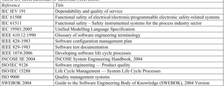
101
The standards listed in Table B1are referenced in this standard.
Table B1 International or national references
Reference Title
IEC IEV 191 Dependability and quality of service
IEC 61508 Functional safety of electrical/electronic/programmable electronic safety-related systems IEC 61511 Functional safety – Safety instrumented systems for the process industry sector
IEC 19501:2005 Unified Modelling Language Specification IEEE 610.12:1990 Glossary of software engineering terminology IEEE 828-1983 Software configuration management plan IEEE 829-1983 Software test documentation
IEEE 1074:2006 Developing software life cycle processes INCOSE SE 2004 INCOSE System Engineering Handbook, 2004 ISO/IEC 9126 Software engineering — Product quality
ISO/IEC 15288 Life Cycle Management — System Life Cycle Processes
ISO 9000 Quality management systems
B 200 DNV references
201
This standard is complimentary to the standards listed in Table B2 and B3.
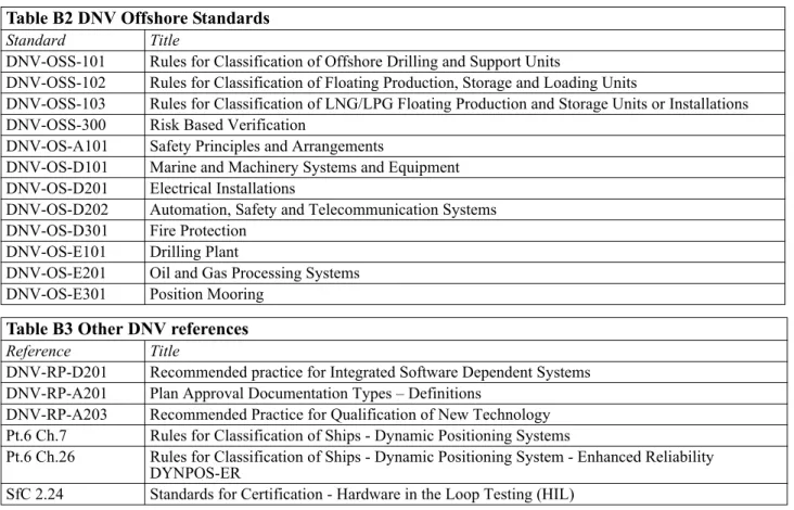
Table B2 DNV Offshore Standards
Standard Title
DNV-OSS-101 Rules for Classification of Offshore Drilling and Support Units
DNV-OSS-102 Rules for Classification of Floating Production, Storage and Loading Units
DNV-OSS-103 Rules for Classification of LNG/LPG Floating Production and Storage Units or Installations DNV-OSS-300 Risk Based Verification
DNV-OS-A101 Safety Principles and Arrangements
DNV-OS-D101 Marine and Machinery Systems and Equipment DNV-OS-D201 Electrical Installations
DNV-OS-D202 Automation, Safety and Telecommunication Systems DNV-OS-D301 Fire Protection
DNV-OS-E101 Drilling Plant
DNV-OS-E201 Oil and Gas Processing Systems DNV-OS-E301 Position Mooring
Table B3 Other DNV references
Reference Title
DNV-RP-D201 Recommended practice for Integrated Software Dependent Systems DNV-RP-A201 Plan Approval Documentation Types – Definitions
DNV-RP-A203 Recommended Practice for Qualification of New Technology Pt.6 Ch.7 Rules for Classification of Ships - Dynamic Positioning Systems
Pt.6 Ch.26 Rules for Classification of Ships - Dynamic Positioning System - Enhanced Reliability DYNPOS-ER
D
ET
N
ORSKE
V
ERITAS
AS
INTEGRATED SOFTWARE DEPENDENT SYSTEMS
CHAPTER 2
TECHNICAL PROVISIONS
CONTENTS
PAGE
Sec. 1
Principles... 11
Sec. 2
Confidence Levels ... 12
Sec. 3
Responsibilities ... 13
Sec. 4
Project Phases and Process Areas ... 15
Sec. 5
ISDS Requirements for Owners... 19
Sec. 6
ISDS Requirements for System Integrators... 22
Sec. 7
ISDS Requirements for Suppliers... 28
SECTION 1
PRINCIPLES
A. General
A 100 Process requirements
101
This standard provides requirements for a process. These requirements are formulated as a set of
activities that apply for specific roles during specific project phases and at specific confidence levels.
A 200 System hierarchy
201
In order to describe the different parts that make up Integrated Software Dependent Systems, this
standard uses the hierarchy defined in Fig.1.
Figure 1
SECTION 2
CONFIDENCE LEVELS
A. Confidence Levels
A 100 Definition of confidence levels
101
Confidence levels are assigned by the owner to a selection of the unit’s functions and systems, based on
evaluations of the importance of these functions in relation to reliability, availability, maintainability and
safety.
102
Confidence levels define the required level of trust that a given function (implemented by one or more
systems) will perform as expected. This standard defines the confidence levels 1 through 3 where the higher
confidence level will require a higher project ambition level with the aim of increasing the dependability of the
systems in scope. The higher confidence levels also include the activities required for the lower ones.
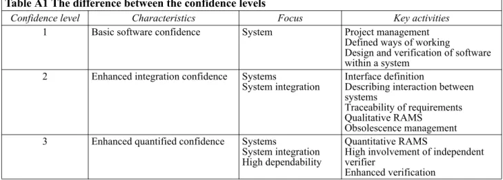
103
Table A1 shows the difference between confidence levels 1, 2 and 3.
104
Ch.3, Sec.1, B200 shows the recommended confidence levels for systems and components relevant for
selected unit types (drilling unit, FPSO etc.).
Guidance note:
See DNV-RP-D201 for general guidance on the principles of assigning confidence levels to functions and systems.
---e-n-d---of---G-u-i-d-a-n-c-e---n-o-t-e---Table A1 The difference between the confidence levels
Confidence level Characteristics Focus Key activities
1 Basic software confidence System Project management
Defined ways of working
Design and verification of software within a system
2 Enhanced integration confidence Systems
System integration Interface definitionDescribing interaction between systems
Traceability of requirements Qualitative RAMS
Obsolescence management 3 Enhanced quantified confidence Systems
System integration High dependability
Quantitative RAMS
High involvement of independent verifier
SECTION 3
RESPONSIBILITIES
A. Activities and Roles
A 100 Activities
101
Each requirement of this standard is formulated as an activity which is assigned to a role, a defined project
phase, and a confidence level. The activities are listed in Sec.5 to 7 and described in detail in Appendix B.
Guidance note:
Each required activity has a unique identifier. The identifier is structured in three parts: Z.YYY.NN. The first part (“Z”) of the activity identifier refers to the project phase. The second part (“YYY”) of the activity identifier refers to the process area. The third part (“NN”) of the activity identifier is a unique number for the activity. For example, A.REQ.2 is the identifier of the 2nd activity of the requirements process area for the basic engineering phase. Some activities are performed in 2 or several phases. In this case, the activity’s phase is described as an “X”. Each “X” activity describes in which phases it shall be performed.X.REQ.1 is the common activity no. 1 for the requirements process area for managing requirement changes in all phases.
---e-n-d---of---G-u-i-d-a-n-c-e---n-o-t-e---102
Several activities require communication between different roles to be carried out. For these activities
the contributing role(s) are specified, in addition to the responsible role. The expected contributions are
specified in this standard, and the contributing role shall provide the specified information to the responsible
role when requested.
Figure 1
A 200 Roles
201
This standard defines requirements on several organisations with responsibilities within the system life
cycle. Each role is assigned activities and has the responsibility to perform the activity with an outcome that
fulfils the specified criteria.
202
Each organisation is assigned one of four predefined roles. The four roles are:
— Owner (OW): In the context of this standard the owner is the organisation who decides to develop the unit
(ship, rig etc.), and provides funding. The operator of the system can be part of the owner's organisation,
or can be a subcontractor acting on behalf of the owner. For a definition of the term owner reference is also
made to DNV-OSS-101 Ch.1, Sec.1, B.
— System integrator (SI): Responsible for the integration of all systems included in the scope of this standard.
The system integrator is normally the shipyard, but parts of the integration may be delegated to other
parties. In such case this shall be clearly defined and documented.
— Supplier (SU): Responsible for the integration and delivery of one or more single systems (drilling control
system, power management system etc.). If the supplier purchases products and services from other
organisations, these are regarded as sub-suppliers, and are under the supplier's responsibility.
— Independent verifier (IV): An organisation that is mandated to independently verify that the system is
developed according to this standard. As part of the classification process for the ISDS notation, DNV shall
take the role of independent verifier.
SECTION 4
PROJECT PHASES AND PROCESS AREAS
A. Project phases
A 100 Introduction
101
All activities in this standard are mapped to the typical project life cycle, see Fig.1.
102
The transitions between the phases represent ISDS milestones. At each milestone the following
information shall be reported by the involved roles:
— status for the compliance to this standard,
— action plans for handling non-conformities,
— risk observations made by the independent verifier.
103
At each milestone a “milestone meeting” should be arranged. The system integrator is responsible for
arranging such meetings at all milestones, except M5 for which the owner is responsible.
104
An ISDS milestone is completed when the owner, the system integrator and the independent verifier
endorse the information presented at the milestone.
Figure 1
Process chart describing the relationship between project phases (A to E) and ISDS milestones (M1 to
M5). ISDS milestone M5 is only applicable for modifications made during the operation phase.
A 200 Basic engineering phase (A)
201
During this phase the technical specification and design of the unit are established, including RAMS
requirements. The main systems which will be included in the scope for ISDS requirements and their
confidence levels are identified. The contract between the owner and the system integrator is established during
this phase.
Guidance note:
The following activities normally take place before the contract between the owner and the system integrator is signed, depending on the confidence level for the different systems:
— Define mission, objectives and shared vision (A.REQ.1, CL1 and above).
— Define operational modes and scenarios to capture expected behaviour (A.REQ.3, CL2 and above). — Define RAM related requirements and objectives (A.RAMS.2, CL2 and above).
— Define procedures (owner) (A.PQA.1, CL1 and above).
---e-n-d---of---G-u-i-d-a-n-c-e---n-o-t-e---A 300 Engineering phase (B)
301
In this phase contracts are established with suppliers, and the suppliers are involved in setting up the
development/configuration of each system. The detailed design of the unit and systems is documented. The
verification, validation, testing and integration strategies, and major interfaces are established, and RAMS
analyses are carried out.
Guidance note:
The ISDS process is normally aligned with the overall building schedule so that steel cutting takes place towards the end of the ISDS engineering phase.
Normally, only one phase B activity takes place before the contracts between the system integrator and the suppliers are signed:
— Submit proposals to system integrator with compliance status (B.REQ.1, CL1 and above).
---e-n-d---of---G-u-i-d-a-n-c-e---n-o-t-e---A 400 Construction phase (C)
401
In this phase the construction and integration of the systems are carried out. Detailed software design,
coding and/or parameterization are performed. Systems and interfaces are tested, validated and verified as part
of this phase.
A 500 Acceptance phase (D)
501
In this phase, the functionality, performance, RAMS requirements and other aspects of the integrated
systems are validated, through commissioning activities, integration testing, and sea trials.
A 600 Operation phase (E)
601
In this phase the unit is in operation. Maintenance and small upgrades are performed as deemed
necessary by the owner.
602
Large upgrades should be managed as separate projects, following a distinct lifecycle based on this
standard.
Guidance note:
Any planned upgrade resulting in the shutdown of the unit or ship for any extended period of time should be regarded as a large upgrade.
---e-n-d---of---G-u-i-d-a-n-c-e---n-o-t-e---B. Process Areas
B 100 Introduction
101
Activities are logically grouped in process areas based on the typical engineering discipline they address.
Each process area spans multiple project phases.
B 200 Requirements engineering (REQ)
201
The requirements engineering process area covers the activities needed to define, document and manage
the requirements on the unit, the systems and the related software.
On CL1, the overall goal and vision for the unit are defined and the requirements on the unit and relevant
systems are specified. A dialogue between the owner/system integrator on one hand and the potential suppliers
on the other is expected to take place in order to align the requirements with the supplier’s systems. The
allocation of requirements to systems shall be documented. No specific methods or formats for the unit or
system requirements are expected.
On CL2, operational modes and scenarios are defined in order to put the requirements into an operational
context, and to detail the interaction between different systems. A trace from requirements to design and
verification shall be documented and maintained.
CL3 introduces additional independent verifier activities.
B 300 Design (DES)
301
The design process area consists of activities to establish a design on different levels. Together with the
interface related activities in the integration process area (INT), this creates the design basis from which the
systems and related software can be produced and verified.
On CL1, each system is designed with identification of major sub-systems and components. The external
interfaces shall be documented and coordinated with other relevant systems.
On CL2, the unit design is documented, maintained, and analysed with focus on integration of the systems. A
strategy for handling of current and future obsolescence is expected to be defined, and design guidelines to be
established. The architecture of relevant systems and software components is detailed and documented,
including new, reused, and parameterized software. The documentation related to any base-products shall be
kept up to date.
CL3 introduces additional independent verifier activities.
B 400 Implementation (IMP)
401
The implementation process area covers the coding and configuration activities needed to create and
customize software modules in order to fulfil the specified design. In addition, associated support
documentation shall be created.
On CL1, the software components are programmed, parameterized and tested based on a baselined design.
On CL2, implementation guidelines and methods are expected to be used as additional input to the
programming and parameterization, and support documentation like user manuals is produced.
B 500 Acquisition (ACQ)
501
The acquisition process area includes activities related to when a supplier uses sub-suppliers to develop
or deliver components/systems. It covers both the situation where configuration and development of the
software components is subcontracted and the situation where the supplier buys 'commercial off the shelf'
(COTS) systems.
On CL1, specific contracts between the supplier and the sub-supplier are established and followed-up. The
components or systems are verified at delivery and it shall be ensured that the delivered component/system can
be integrated into the system/unit in question.
On CL2, the COTS systems are selected based on defined criteria. Intermediate deliveries are reviewed, and
acquired components or systems are monitored with regards to obsolescence during the operation phase.
CL3 does not add any requirements.
B 600 Integration (INT)
601
The integration process area covers the assembly of the systems into the unit, and activities to coordinate
the interfaces between the systems.
On CL1, the responsibilities regarding each system and how it is to be integrated are defined.
On CL2, a specific integration plan is produced. Inter-system interfaces are coordinated and systems checked
against pre-defined criteria before the integration takes place.
CL3 introduces additional independent verifier activities.
B 700 Verification and Validation (VV)
701
The verification and validation process area addresses the quality assurance activities needed to ensure
that that each software component, each system and the integrated systems in concert perform as expected and
fulfil the needs of the intended use.
On CL1, the focus is on the individual systems. It is required that a verification strategy is defined, and that
basic verification activities like FAT, peer reviews, and qualification of reused software are prepared and
performed according to this strategy. It is also expected that the owner performs validation testing during the
acceptance phase, and when modifications and upgrades are performed during the operation phase.
On CL2 the focus is on the functionality and performance of the integrated systems working together, and on
early verification of the correctness and the completeness of requirements, interface specifications, user
interfaces, and design documentation. The verification and validation results are expected to be analysed and
compared with defined targets.
On CL3, the focus is on an elaborated system testing, and that an independent party performs testing on the
system(s). Additional independent verifier activities are also introduced.
B 800 Reliability, Availability, Maintainability and Safety (RAMS)
801
The reliability, availability, maintainability and safety (RAMS) process area gathers the activities
dealing with the definition, analysis and verification of the RAMS properties of the unit and specific systems.
Security aspects are also included.
On CL1, the focus is on the safety part, meaning that applicable laws and regulations regarding safety are
identified, and that software and software failures are taken into account when doing safety analysis. In the
operation phase a structured way of doing maintenance is required.
On CL 2, the focus is on the reliability, availability and maintainability (RAM) of the systems in question.
Goals regarding RAM are established, analysed and verified, but the goals can be qualitative in nature. Risks
and mitigations related to the RAMS aspects are managed. The activities related to handling of the RAMS
aspects are planned and followed-up during the project. Security aspects are dealt with by performing security
audits.
On CL3, the focus is on RAM objectives that are explicitly defined, analysed and proven fulfilled. In order to
achieve this, the RAM objectives need to be quantitative. Additional independent verifier activities are also
introduced.
B 900 Project Management (PM)
901
The project management process area covers the activities required to make sure that the project plans
for the different organizations involved are created, synchronized and followed-up.
On CL1, basic project management activities regarding project planning and tracking are required, and there
are no additional requirements at CL2 and CL3.
B 1000 Risk Management (RISK)
1001
The risk management process area covers activities related to identifying, mitigating and tracking
product and project risks related to systems and software. Based on the risks, the different systems are assigned
a confidence level.
On CL1, risks are identified, reviewed, tracked, and updated.
On CL2, also the risk mitigation actions shall be tracked to verify that they have the expected effect on the risk.
CL3 introduces additional independent verifier activities.
B 1100 Process and Quality Assurance (PQA)
1101
The process and quality assurance process area covers the activities needed to define and follow up the
way of working within the project. It also covers the activities needed to make sure that the involved
organizations fulfil the requirements in this standard.
On CL1, the applicable procedures for each organization are defined and when necessary coordinated with the
other roles. The adherence to the defined procedures is followed-up by each organization. DNV will follow-up
on the adherence to the requirements in this standard.
There are no additional requirements at CL2 and CL3.
B 1200 Configuration Management (CM)
1201
The configuration management area covers activities to make sure that changes to documents and
software are performed in a controlled way, and to ensure the integrity and consistency of the systems, their
configuration, and all related work products (requirements, design, interface specifications, specifications,
source code, documentation, etc.).
On CL1, the configuration management area includes all required activities, and there are no additional
requirements at CL2 and CL3.
SECTION 5
ISDS REQUIREMENTS FOR OWNERS
A. Owner requirements
A 100 Requirements under the owner’s responsibility
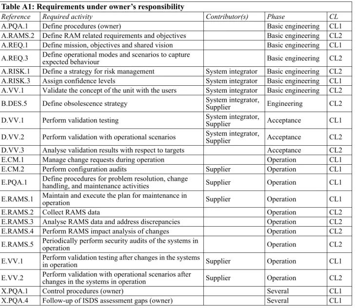
101
The following Table A1 lists the requirements under the owner’s responsibility. See also Table A2 for
the associated acceptance criteria and Table A3 for documentation criteria.
102
The owner shall also contribute to requirements that are under the responsibility of other roles.
103
Appendix B fully specifies the requirements for all roles.
Table A1: Requirements under owner’s responsibility
Reference Required activity Contributor(s) Phase CL
A.PQA.1 Define procedures (owner) Basic engineering CL1
A.RAMS.2 Define RAM related requirements and objectives Basic engineering CL2 A.REQ.1 Define mission, objectives and shared vision Basic engineering CL1 A.REQ.3 Define operational modes and scenarios to capture expected behaviour Basic engineering CL2 A.RISK.1 Define a strategy for risk management System integrator Basic engineering CL2 A.RISK.3 Assign confidence levels System integrator Basic engineering CL1 A.VV.1 Validate the concept of the unit with the users System integrator Basic engineering CL2 B.DES.5 Define obsolescence strategy System integrator,Supplier Engineering CL2 D.VV.1 Perform validation testing System integrator,Supplier Acceptance CL1 D.VV.2 Perform validation with operational scenarios System integrator,Supplier Acceptance CL2 D.VV.3 Analyse validation results with respect to targets Acceptance CL2
E.CM.1 Manage change requests during operation Operation CL1
E.CM.2 Perform configuration audits Supplier Operation CL1
E.PQA.1 Define procedures for problem resolution, change handling, and maintenance activities Supplier Operation CL1 E.RAMS.1 Maintain and execute the plan for maintenance in operation Supplier Operation CL1
E.RAMS.2 Collect RAMS data Operation CL2
E.RAMS.3 Analyse RAMS data and address discrepancies Operation CL2
E.RAMS.4 Perform RAMS impact analysis of changes Operation CL2
E.RAMS.5 Periodically perform security audits of the systems in operation Operation CL2 E.VV.1 Perform validation testing after changes in the systems in operation Supplier Operation CL1 E.VV.2 Perform validation with operational scenarios after changes in the systems in operation Supplier Operation CL2
X.PQA.1 Control procedures (owner) Several CL1
A 200 Acceptance criteria for owner assessments
201
The following Table A2 lists the acceptance criteria for assessments of the owner. The following
evidence shall be presented to the independent verifier during assessments to document that the required
activities have been performed.
202
See also Table A3 for the required documentation criteria.
Table A2: Acceptance criteria for assessments of owner
Reference Assessment criteria A.PQA.1
A quality system, documents, minutes of meetings, or other relevant information showing: A defined way of working for the major activities in the project, clear roles and responsibilities and defined ways of interaction between the different organizations (e.g. owner, system integrator, supplier, independent verifier, and others).
A.RAMS.2 Listing of RAM requirements.For CL2: qualitative requirements are acceptable.
For CL3: quantitative requirements (objectives) are required.
A.REQ.1 Unit design intention and philosophy: The vision of the unit/system, descriptions of the unit/systems overall behaviour and the expected business/safety/environmental performance. A.REQ.3 Vessel specification: description of the operational modes and corresponding key operational scenarios, detailed to the level of the different systems. A.RISK.1 Risk management procedure.Blank risk register.
A.RISK.3 Confidence level matrix for the relevant systems.
A.VV.1 Unit concept presentation: Simulations and Minutes of System Concept Review Meeting.FEED study.
B.DES.5 Obsolescence management plan: Authorised vendor list, Spare parts list (hardware & software), stock, alternate spare parts list, management of intellectual property. Obsolescence criteria for software. Manufacturer preferred equipment list.
D.VV.1 Test procedure: black box tests, boundary tests, software behaviour and parameterisation and calibration.Test reports: executed consistent with procedure. Test issue list: deviations (punches) and variations.
D.VV.2 Test procedure: operational scenarios.Test reports: tests performed in compliance with procedure and coverage of scenarios.
D.VV.3 Test procedure: quality criteria.Test reports: analysis of the results. Test issue list.
E.CM.1 Change requests Impact analysis Change orders Work orders Problem reports Release notes Maintenance logs
E.CM.2 Configuration audit reports.
E.PQA.1
Configuration management plan.
Configuration management procedure: migration issues and software obsolescence (ref E.ACQ.1). Maintenance procedures: procedures for the maintenance, software update, migration and retirement, backup and restore procedures and procedures for receiving, recording, resolving, tracking problems and modification requests.
Change management procedure. Issue tracking and resolution procedure.
E.RAMS.1
Maintenance plan: configuration items, audit activities, maintenance activities, expected software update, migration and retirement activities, maintenance intervals and tailored procedures for the maintenance in operation.
Malicious software scan log files records. Maintenance logs.
E.RAMS.2 RAMS data collection system.RAMS data collected. E.RAMS.3 RAMS analysis.
E.RAMS.4 Impact analysis showing RAMS evaluation. E.RAMS.5 Security audit report.
A 300 Documentation criteria for the owner
301
The table below lists all documents to be sent to the independent verifier and in which activities the
independent verifier is going to use the different documents.
302
When the independent verifier is expected to comment on the document, the word ‘reviewed’ is
employed. For documents which serve as background information to put the reviewed documents in a context,
the word ‘used’ is employed.
303
Most documents are provided for information (FI). The only document that is sent to the independent
verifier for approval (AP) is the corrective action plan.
E.VV.1 Test procedure: includes black box tests and includes boundary tests.Test reports: consistent with procedure.
E.VV.2 Test procedures: Covering relevant Operational scenarios.Test reports: tests performed in compliance with procedure and analysis of the results.
X.PQA.1 Proof that process adherence is being assessed: Quality control records, Project control records and Minutes of meetings, or other relevant information. X.PQA.4 Corrective action plan: Responsibility allocation for actions, Records of actions taken and Evidence of implementation of the actions.
Table A3: Documents required for review
Reference Documents
A.PQA.1 No documentation to be submitted to DNV for review.
A.RAMS.2
List of RAM requirements unit (FI): - reviewed in A.IV.2 and B.IV.4 at CL3 - used in D.IV.3 at CL3.
List of RAM requirements system (FI) used in C.IV.3 at CL3. A.REQ.1 Design Philosophy (FI) used in A.IV.1 at CL3.
A.REQ.3 Vessel specification (FI) reviewed in A.IV.1 at CL3. A.RISK.1 No documentation to be submitted to DNV for review. A.RISK.3 Vessel specification (confidence levels) (FI):- reviewed in A.IV.1 at CL3
- used in A.IV.2 and B.IV.4 at CL3.
A.VV.1 No documentation to be submitted to DNV for review. B.DES.5 No documentation to be submitted to DNV for review.
D.VV.1 Test procedure for quay and sea trials (FI) and Report from quay and sea trials (FI) reviewed in D.IV.1 at CL2 and CL3. Report from quay and sea trials (FI) used in D.IV.2 at CL3.
D.VV.2 Test procedure (FI) and Test report (FI) reviewed in D.IV.1 at CL2 and CL3.Test report (FI) used in D.IV.2 at CL3. D.VV.3 Verification analysis report (FI) reviewed in D.IV.2 at CL3.
E.CM.1 No documentation to be submitted to DNV for review. E.CM.2 No documentation to be submitted to DNV for review. E.PQA.1 No documentation to be submitted to DNV for review. E.RAMS.1 No documentation to be submitted to DNV for review. E.RAMS.2 No documentation to be submitted to DNV for review. E.RAMS.3 No documentation to be submitted to DNV for review. E.RAMS.4 No documentation to be submitted to DNV for review. E.RAMS.5 No documentation to be submitted to DNV for review.
E.VV.1 Test procedure (FI) and Test report (FI) reviewed in E.IV.1 at CL3. E.VV.2 Test procedure (FI) and Test report (FI) reviewed in E.IV.1 at CL3. X.PQA.1 No documentation to be submitted to DNV for review.
X.PQA.4 Corrective action plan (AP) reviewed and approved in X.IV.1.
Table A2: Acceptance criteria for assessments of owner (Continued)
SECTION 6
ISDS REQUIREMENTS FOR SYSTEM INTEGRATORS
A. System integrator requirements
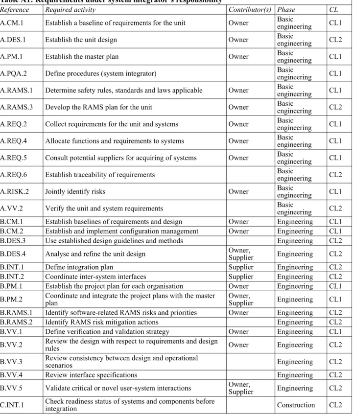
A 100 Requirements under the system integrator’s responsibility
101
The following Table A1 lists the requirements under the system integrator’s responsibility. See also
Table A2 for the associated acceptance criteria and Table A3 for documentation criteria.
102
The system integrator shall also contribute to requirements that are under the responsibility of other roles.
103
Appendix B fully specifies the requirements for all roles.
Table A1: Requirements under system integrator’s responsibility
Reference Required activity Contributor(s) Phase CL
A.CM.1 Establish a baseline of requirements for the unit Owner Basic engineering CL1
A.DES.1 Establish the unit design Owner Basic engineering CL2
A.PM.1 Establish the master plan Owner Basic engineering CL1
A.PQA.2 Define procedures (system integrator) Basic engineering CL1
A.RAMS.1 Determine safety rules, standards and laws applicable Owner Basic engineering CL1 A.RAMS.3 Develop the RAMS plan for the unit Owner Basic engineering CL2 A.REQ.2 Collect requirements for the unit and systems Owner Basic engineering CL1 A.REQ.4 Allocate functions and requirements to systems Owner Basic engineering CL1 A.REQ.5 Consult potential suppliers for acquiring of systems Owner Basic engineering CL1
A.REQ.6 Establish traceability of requirements Basic engineering CL2
A.RISK.2 Jointly identify risks Owner Basic engineering CL1
A.VV.2 Verify the unit and system requirements Basic engineering CL2
B.CM.1 Establish baselines of requirements and design Owner Engineering CL1 B.CM.2 Establish and implement configuration management Owner Engineering CL1
B.DES.3 Use established design guidelines and methods Engineering CL2
B.DES.4 Analyse and refine the unit design Owner,Supplier Engineering CL2
B.INT.1 Define integration plan Supplier Engineering CL2
B.INT.2 Coordinate inter-system interfaces Supplier Engineering CL2
B.PM.1 Establish the project plan for each organisation Owner Engineering CL1 B.PM.2 Coordinate and integrate the project plans with the master plan Owner,Supplier Engineering CL1 B.RAMS.1 Identify software-related RAMS risks and priorities Owner Engineering CL2
B.RAMS.2 Identify RAMS risk mitigation actions Engineering CL2
B.VV.1 Define verification and validation strategy Owner Engineering CL1 B.VV.2 Review the design with respect to requirements and design rules Owner Engineering CL2 B.VV.3 Review consistency between design and operational scenarios Engineering CL2
B.VV.4 Review interface specifications Engineering CL2
B.VV.5 Validate critical or novel user-system interactions Owner,Supplier Engineering CL2 C.INT.1 Check readiness status of systems and components before integration Construction CL2
A 200 Acceptance criteria for system integrator assessments
201
The following Table A2 lists the acceptance criteria for assessments of the system integrator. The
following evidence shall be presented to the independent verifier during assessments to document that the
required activities have been performed.
202
See also Table A3 for the required documentation criteria.
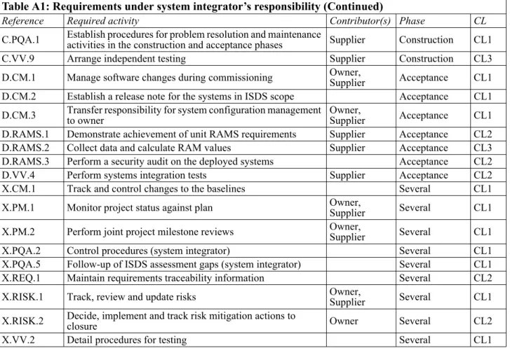
C.PQA.1 Establish procedures for problem resolution and maintenance activities in the construction and acceptance phases Supplier Construction CL1
C.VV.9 Arrange independent testing Supplier Construction CL3
D.CM.1 Manage software changes during commissioning Owner,Supplier Acceptance CL1 D.CM.2 Establish a release note for the systems in ISDS scope Acceptance CL1 D.CM.3 Transfer responsibility for system configuration management to owner Owner,Supplier Acceptance CL1 D.RAMS.1 Demonstrate achievement of unit RAMS requirements Supplier Acceptance CL2
D.RAMS.2 Collect data and calculate RAM values Supplier Acceptance CL3
D.RAMS.3 Perform a security audit on the deployed systems Acceptance CL2
D.VV.4 Perform systems integration tests Supplier Acceptance CL2
X.CM.1 Track and control changes to the baselines Several CL1
X.PM.1 Monitor project status against plan Owner,Supplier Several CL1
X.PM.2 Perform joint project milestone reviews Owner,Supplier Several CL1
X.PQA.2 Control procedures (system integrator) Several CL1
X.PQA.5 Follow-up of ISDS assessment gaps (system integrator) Several CL1
X.REQ.1 Maintain requirements traceability information Several CL2
X.RISK.1 Track, review and update risks Owner,Supplier Several CL1
X.RISK.2 Decide, implement and track risk mitigation actions to closure Owner Several CL2
X.VV.2 Detail procedures for testing Several CL1
Table A2: Acceptance criteria for assessments of system integrator
Reference Assessment criteria
A.CM.1 Approved and controlled unit requirements document.Revision history of unit requirements document.
A.DES.1 Unit design: unit design specifications, systems/network topology and functional descriptions. A.PM.1 Master plan: Activities, work breakdown structure (WBS), schedule, and milestones.
A.PQA.2
A quality system, documents, minutes of meetings, or other relevant information showing: A defined way of working for the major activities in the project, clear roles and responsibilities and defined ways of interaction between the different organizations (e.g. owner, system integrator, supplier, independent verifier, and others).
A.RAMS.1 Listing of regulatory requirements that apply regarding safety.Resolution of conflicting rules. Application guidelines.
A.RAMS.3
Plan(s) showing the methods, tools, and procedures to be used for RAMS activities. Schedule of RAMS activities.
Expectations on the suppliers’ RAMS plan. RAM data to be collected (CL3).
A.REQ.2 Vessel specification: operational requirements, functional requirements, non-functional requirements and technical constraints. A.REQ.4 Design specification (or requirements) for the relevant systems.
A.REQ.5 System request for proposal (RfP): functional specifications, generic system requirements and obsolescence information. Requirements compliance information (on CL2 and above).
A.REQ.6 Traceability information between requirements on unit level and requirements on the different systems.Defined mechanisms and ambition-level regarding requirements traceability. A.RISK.2 Project risk list: risk list with risks related to e.g. requirements, schedule, effort, quality, performance, consistency and obsolescence (for both hardware and software).
Table A1: Requirements under system integrator’s responsibility (Continued)
A.VV.2 Review records of the unit requirements.Review records for the system requirements.
B.CM.1
Baseline repositories. Identification of baselines.
Approved and controlled documents (baselines) for: unit specifications, unit design, system requirements, system design, interface specifications and base products.
B.CM.2
Configuration management plan: Definition of a Change Control Board (CCB) process or similar, identification of required baselines, required baseline content, change request forms.
Change requests and change decisions. Version history information of baselines.
Defined rules and mechanisms for version control. Effective implementation of version control mechanisms. B.DES.3 System design guidelines: including RAMS related aspects.Unit design guidelines: including RAMS related aspects.
B.DES.4 Updated unit design documentation: unit design specifications, systems/network topology with software components, interface specifications, and functional descriptions.
B.INT.1
Plan for integration of systems into unit: The responsibilities of the different organizations, dependencies among systems, sequence for integration, integration environment, tests and integration readiness criteria.
Plan for integration of sub-systems and components into systems (when required): Dependencies among systems, sub-systems and components, sequence for integration, integration environment, tests and integration readiness criteria.
B.INT.2
Interface overview/matrix information with assigned responsibilities.
Agreed inter-system interface specifications containing: protocol selected, definition of commands, messages, data and alarms to be communicated and specifications of message formats.
Interface definition and verification status.
B.PM.1
Schedule.
Project plan: WBS, technical attributes used for estimating, effort and costs estimates, deliverables and milestones, configuration management plan.
Resource allocation. B.PM.2 Master plan.Project plans.
B.RAMS.1 RAMS hazard and risk list showing consideration of software risks.Defined risk identification and analysis methods. Relevant risks are communicated to other roles.
B.RAMS.2 RAMS hazard and risk mitigation list showing mitigation actions for software risks.Relevant mitigation actions are communicated to other roles
B.VV.1
Verification strategy: which part to verify: unit, system, sub-system, component, module, design documents.
Method specification documents, etc.: which methods to use for this verification: testing, inspection, code analysis, simulation, prototyping, peer review techniques, quality criteria and targets, which test types to use: functional, performance, regression, user interface, negative, what environment to use for verification and identification of the test stages (e.g. sea trials, integration tests, commissioning, FAT, internal testing, component testing) to be used for the verification and the schedule for those tests. Validation strategy: products to be validated, validation criteria, operational scenarios, methods and environments.
B.VV.2 Documented design review records addressing: requirements verification, design rules and verification of uncertainties. B.VV.3 Minutes from review: review results considering consistency of interface/function/component/scenarios. B.VV.4 Interface specification reviews addressing at least: consistency between input and output signals, frequency and scan rates, deadlocks, propagation of failures from one part to another, engineering units,
network domination.
B.VV.5 Validation records including: workshop minutes, user representative’s participation and comments and agreed action lists. C.INT.1 Integration readiness criteria fulfilled per component and per system.
C.PQA.1
Agreed maintenance procedures: Procedures for general system maintenance activities and procedures for software update, backup and roll-back.
Agreed problem resolution procedures: Procedures for receiving, recording, resolving, tracking problems (punches) and modification requests.
C.VV.9 Test procedure: covering the system and its interfaces.Test report.
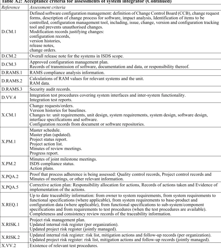
Table A2: Acceptance criteria for assessments of system integrator (Continued)
D.CM.1
Defined software configuration management: definition of Change Control Board (CCB), change request forms, description of change process for software, impact analysis, Identification of items to be controlled, configuration management tool, including, issue, change, version and configuration tracking tool and prevents unauthorised changes.
Modification records justifying changes: configuration records,
version histories, release notes, change orders.
D.CM.2 Overall release note for the systems in ISDS scope.
D.CM.3 Approved configuration management plan.Records of transmission of software, documentation and data, or responsibility thereof. D.RAMS.1 RAMS compliance analysis information.
D.RAMS.2 Calculations of RAM values for relevant systems and the unit.RAM data. D.RAMS.3 Security audit records.
D.VV.4 Integration test procedures covering system interfaces and inter-system functionality.Integration test reports.
X.CM.1
Change requests/orders. Version histories for baselines.
Changes to: unit requirements, unit design, system requirements, system design, software design, interface specifications and software.
Configuration records from document or software repositories.
X.PM.1
Master schedule. Master plan (updated). Project status report. Project action list.
Minutes of review meetings. Progress report.
X.PM.2 Minutes of joint milestone meetings.ISDS compliance status. Action plans.
X.PQA.2 Proof that process adherence is being assessed: Quality control records, Project control records and Minutes of meetings, or other relevant information. X.PQA.5 Corrective action plan: Responsibility allocation for actions, Records of actions taken and Evidence of implementation of the actions.
X.REQ.1
Up to date traceability information: from owner to system requirements, from system requirements to functional specifications (where applicable), from system requirements to base-product and
configuration data (where applicable), from functional specifications to sub-system/component specifications and from requirements to test procedures (when the test procedures are available). Completeness and consistency review records of the traceability information.
X.RISK.1 Project risk management plan.Updated internal risk register (per organization). Updated project risk register (jointly managed).
X.RISK.2 Updated internal risk register: risk list, mitigation actions and follow-up records (per organization).Updated project risk register: risk list, mitigation actions and follow-up records (jointly managed). X.VV.2 Existence of relevant test procedures.
Table A2: Acceptance criteria for assessments of system integrator (Continued)
A 300 Documentation criteria for the system integrator
301
The table below lists all documents to be sent to the independent verifier and in which activities the
independent verifier is going to use the different documents.
302
When the independent verifier is expected to comment on the document, the word ‘reviewed’ is
employed. For documents which serve as background information to put the reviewed documents in a context,
the word ‘used’ is employed.
303
Most documents are provided for information (FI). The only document that is sent to the independent
verifier for approval (AP) is the corrective action plan.
Table A3: Documents required for review
Reference Documents
A.CM.1 No documentation to be submitted to DNV for review. A.DES.1 No documentation to be submitted to DNV for review. A.PM.1 No documentation to be submitted to DNV for review. A.PQA.2 No documentation to be submitted to DNV for review.
A.RAMS.1
List of regulatory requirements unit (FI): - reviewed in A.IV.2 at CL3
- used in B.IV.4 and D.IV.3 at CL3.
List of regulatory requirements system (FI) used in C.IV.3 at CL3. A.RAMS.3 Plan for handling of RAMS (FI):- reviewed in A.IV.2 at CL3
- used in B.IV.4 at CL3.
A.REQ.2 Vessel specification (FI) reviewed in A.IV.1 at CL3. A.REQ.4 Specification (FI) reviewed in A.IV.1 at CL3.
A.REQ.5 No documentation to be submitted to DNV for review. A.REQ.6 Traceability matrices (FI) used in A.IV.1 at CL3. A.RISK.2 No documentation to be submitted to DNV for review. A.VV.2 No documentation to be submitted to DNV for review. B.CM.1 No documentation to be submitted to DNV for review. B.CM.2 No documentation to be submitted to DNV for review.
B.DES.3 RAMS design guidelines and methods for the vessel (FI) used in B.IV.1 at CL3.RAMS design guidelines and methods for the system (FI) used in B.IV.1 at CL3.
B.DES.4
Interface description (FI) reviewed in B.IV.1 at CL3, Functional description (FI) reviewed in B.IV.1 at CL3, Block (topology) diagram (FI):
- reviewed in B.IV.1 at CL3 - used in B.IV.2 at CL2 and CL3. B.INT.1 Integration plan (FI):- reviewed in B.IV.2 at CL2 and CL3
- used in C.IV.1 at CL3.
B.INT.2 Interface description (FI) used in B.IV.2 at CL2 and CL3. B.PM.1 No documentation to be submitted to DNV for review. B.PM.2 No documentation to be submitted to DNV for review.
B.RAMS.1 RAMS risk register (FI) and RAMS risk analysis documentation (FI) reviewed in B.IV.3 at CL3. B.RAMS.2 RAMS risk register (FI):- reviewed in B.IV.3 at CL3
- used in C.IV.3 and D.IV.3 at CL3. B.VV.1 Verification and validation strategy (FI):- reviewed in B.IV.2, at CL2 and CL3
- used in C.IV.1 at CL3, and C.IV.2 and D.IV.1 at CL2 and CL3. B.VV.2 No documentation to be submitted to DNV for review.
B.VV.3 No documentation to be submitted to DNV for review. B.VV.4 No documentation to be submitted to DNV for review. B.VV.5 No documentation to be submitted to DNV for review. C.INT.1 No documentation to be submitted to DNV for review. C.PQA.1 No documentation to be submitted to DNV for review.
C.VV.9 Independent test procedure (FI) and Independent test report (FI) reviewed in D.IV.1 at CL3.Independent test report (FI) used in D.IV.2 at CL3. D.CM.1 No documentation to be submitted to DNV for review.
D.CM.3 No documentation to be submitted to DNV for review. D.RAMS.1 RAMS compliance report (FI) reviewed in D.IV.3 at CL3. D.RAMS.2 RAM report (FI) unit reviewed in D.IV.3.RAM report (FI) system used in D.IV.3.
D.RAMS.3 Security audit report (FI) used in D.IV.3 at CL3.
D.VV.4 Test procedure (FI) and Test report (FI) reviewed in D.IV.1 at CL2 and CL3.Test report (FI) used in D.IV.2 at CL3. X.CM.1 No documentation to be submitted to DNV for review.
X.PM.1 No documentation to be submitted to DNV for review. X.PM.2 No documentation to be submitted to DNV for review. X.PQA.2 No documentation to be submitted to DNV for review. X.PQA.5 Corrective action plan (AP) reviewed and approved in X.IV.1.
X.REQ.1 Traceability matrices (FI) used in B.IV.1 and C.IV.1 at CL3, and in C.IV.2 at CL2 and CL3. X.RISK.1 No documentation to be submitted to DNV for review.
X.RISK.2 No documentation to be submitted to DNV for review. X.VV.2 No documentation to be submitted to DNV for review.
Table A3: Documents required for review (Continued)
SECTION 7
ISDS REQUIREMENTS FOR SUPPLIERS
A. Supplier requirements
A 100 Requirements under the supplier’s responsibility
101
The following Table A1 lists the requirements under the supplier’s responsibility. See also Table A2 for
the associated acceptance criteria and Table A3 for documentation criteria.
102
The supplier shall also contribute to requirements that are under the responsibility of other roles.
103
Appendix B fully specifies the requirements for all roles.
Table A1: Requirements under supplier’s responsibility
Reference Required activity Contributor(s) Phase CL
B.ACQ.1 Select COTS products based on defined criteria Engineering CL2
B.ACQ.2 Establish contract with sub-suppliers Engineering CL1
B.CM.1 Establish baselines of requirements and design Owner Engineering CL1 B.CM.2 Establish and implement configuration management Owner Engineering CL1
B.DES.1 Design the system System integrator Engineering CL1
B.DES.2 Design each software component Engineering CL2
B.DES.3 Use established design guidelines and methods Engineering CL2
B.DES.5 Define obsolescence strategy System integrator,Supplier Engineering CL2
B.INT.1 Define integration plan Supplier Engineering CL2
B.PM.1 Establish the project plan for each organisation Owner Engineering CL1
B.PQA.1 Define procedures (supplier) Engineering CL1
B.RAMS.1 Identify software-related RAMS risks and priorities Owner Engineering CL2
B.RAMS.2 Identify RAMS risk mitigation actions Engineering CL2
B.RAMS.3 Consider software failure modes in safety analysis activities Engineering CL1 B.RAMS.4 Develop the RAMS plan for the system System integrator Engineering CL2 B.REQ.1 Submit proposals to system integrator with compliance status Engineering CL1 B.REQ.2 Refine system requirements into software component requirements Engineering CL2
B.REQ.3 Detail operational scenarios Engineering CL2
B.VV.1 Define verification and validation strategy Owner Engineering CL1 B.VV.2 Review the design with respect to requirements and design rules Owner Engineering CL2 B.VV.3 Review consistency between design and operational scenarios Engineering CL2
B.VV.4 Review interface specifications Engineering CL2
C.ACQ.1 Accept deliverables Construction CL1
C.ACQ.2 Ensure transition and integration of the delivered product Construction CL1 C.IMP.1 Develop and configure the software components from design Construction CL1 C.IMP.2 Develop support documentation Owner,System integrator Construction CL2
C.IMP.3 Perform software component testing Construction CL1
C.IMP.4 Use established software implementation guidelines and methods Construction CL2 C.INT.1 Check readiness status of systems and components before integration Construction CL2 C.RAMS.1 Demonstrate achievement of system RAMS requirements Construction CL2 C.RAMS.2 Evaluate software systems and software components against RAM objectives Construction CL3 C.RAMS.3 Prepare a plan for system maintenance during operation Owner Construction CL1
A 200 Acceptance criteria for supplier assessments
201
The following Table A2 lists the acceptance criteria for assessments of the supplier. The following
evidence shall be presented to the independent verifier during assessments to document that the required
activities have been performed.
202
See also Table A3 for the required documentation criteria.
C.VV.2 Review software parameterisation data System integrator Construction CL1
C.VV.3 Perform internal testing System integrator Construction CL2
C.VV.4 Perform high integrity internal testing System integrator Construction CL3 C.VV.5 Perform code analysis on new and modified software Construction CL2 C.VV.6 Analyse verification results with respect to targets System integrator Construction CL2
C.VV.7 Qualify reused software Construction CL1
C.VV.8 Perform Factory Acceptance Tests (FAT) Owner,System integrator Construction CL1
E.ACQ.1 Manage and monitor obsolescence Operation CL2
E.CM.1 Manage change requests during operation Operation CL1
E.RAMS.3 Analyse RAMS data and address discrepancies Operation CL2
E.RAMS.4 Perform RAMS impact analysis of changes Operation CL2
X.ACQ.1 Monitor contract execution and changes Several CL1
X.ACQ.2 Review intermediate deliverables Several CL2
X.CM.1 Track and control changes to the baselines Several CL1
X.CM.2 Establish a release note for the delivered system Several CL1
X.DES.1 Update the base-product design documentation Several CL2
X.PM.1 Monitor project status against plan Owner,Supplier Several CL1
X.PQA.3 Control procedures (supplier) Several CL1
X.PQA.6 Follow-up of ISDS assessment gaps (supplier) Several CL1
X.REQ.1 Maintain requirements traceability information Several CL2
X.RISK.1 Track, review and update risks Owner,Supplier Several CL1
X.RISK.2 Decide, implement and track risk mitigation actions to closure Owner Several CL2 X.VV.1 Perform verification and validation on added and modified software components Owner Several CL1
X.VV.2 Detail procedures for testing Several CL1
Table A2: Acceptance criteria for assessments of supplier
Reference Assessment criteria
B.ACQ.1 COTS product selection procedure: obsolescence management.COTS product selection matrix: rationale for selection, selection criteria, evaluations and selection. B.ACQ.2 Supplier agreement: product or component specifications, functional specifications, technical acceptance criteria, ownership transfer conditions, delivery strategy, provisions for review of intermediate deliveries.
B.CM.1
Baseline repositories. Identification of baselines.
Approved and controlled documents (baselines) for: unit specifications, unit design, system requirements, system design, interface specifications and base products.
B.CM.2
Configuration management plan: Definition of a Change Control Board (CCB) process or similar, identification of required baselines, required baseline content, change request forms.
Change requests and change decisions. Version history information of baselines.
Defined rules and mechanisms for version control. Effective implementation of version control mechanisms.
B.DES.1 Design for system (hardware & software): functional description, user interface descriptions, block/topology diagrams with software components, external interface descriptions and internal interface descriptions.
B.DES.2
Component design for each software component, in sufficient detail so as to proceed to the making of the software: structural description, functional description, behaviour description, parameters (default, intervals, as-designed), interfaces description, allocation of software to hardware and assumptions and known limitations of the design.
Table A1: Requirements under supplier’s responsibility (Continued)
B.DES.3 System design guidelines: including RAMS related aspects.Unit design guidelines: including RAMS related aspects.
B.DES.5 Obsolescence management plan: Authorised vendor list, Spare parts list (hardware & software), stock, alternate spare parts list, management of intellectual property. Obsolescence criteria for software. Manufacturer preferred equipment list.
B.INT.1
Plan for integration of systems into unit: The responsibilities of the different organizations, dependencies among systems, sequence for integration, integration environment, tests and integration readiness criteria. Plan for integration of sub-systems and components into systems (when required): Dependencies among systems, sub-systems and components, sequence for integration, integration environment, tests and integration readiness criteria.
B.PM.1
Schedule.
Project plan: WBS, technical attributes used for estimating, effort and costs estimates, deliverables and milestones, configuration management plan.
Resource allocation.
B.PQA.1
A quality system, documents, minutes of meetings, or other relevant information showing: A defined way of working for the major activities in the project, Clear roles and responsibilities and Defined ways of interaction between the different organizations (e.g. owner, system integrator, supplier, independent verifier, and others).
B.RAMS.1 RAMS hazard and risk list showing consideration of software risks.Defined risk identification and analysis methods. Relevant risks are communicated to other roles.
B.RAMS.2 RAMS hazard and risk mitigation list showing mitigation actions for software risks.Relevant mitigation actions are communicated to other roles B.RAMS.3 Safety analysis showing consideration of software failure modes.
B.RAMS.4
Plan showing objectives, methods, tools, and procedures to be used, consistent with the RAMS plan for the unit.
Schedule of RAMS activities. RAM data to be collected (CL3).
B.REQ.1 Submitted technical proposal for the system: system breakdown, alternatives and options, description of customisation or parameterisation of existing products (including software), requirements compliance matrix and software lifecycle information (including licensing, ownership and obsolescence).
B.REQ.2 Refined component requirements and specification.Requirement allocation matrix.
B.REQ.3 System/component behaviour and interaction specification and descriptions: use cases, sequences (including signal usage), state diagrams, interlocks, degraded sequences, performance targets and constraints and limitations.
B.VV.1
Verification strategy: which part to verify: unit, system, sub-system, component, module, design documents.
Method specification documents, etc.: which methods to use for this verification: testing, inspection, code analysis, simulation, prototyping, peer review techniques, quality criteria and targets, which test types to use: functional, performance, regression, user interface, negative, what environment to use for verification and identification of the test stages (e.g. sea trials, integration tests, commissioning, FAT, internal testing, component testing) to be used for the verification and the schedule for those tests.
Validation strategy: products to be validated, validation criteria, operational scenarios, methods and environments.
B.VV.2 Documented design review records addressing: requirements verification, design rules and verification of uncertainties. B.VV.3 Minutes from review: review results considering consistency of interf