Argon ion laser-induced fluorescence with diode lasers
G. D. Severn,a)D. A. Edrich, and R. McWilliams
Department of Physics & Astronomy, University of California, Irvine, Irvine, California 92627
~Received 8 August 1997; accepted for publication 20 October 1997!
Diode lasers have been used for ion temperature measurements in ArII plasmas by finding new
laser-induced fluorescence~LIF!schemes suited to the present range of available wavelengths. The
new LIF schemes require excitation at 664, 669, and 689 nm, all near industry-standard wavelengths. Conventional LIF measurements performed by dye lasers in ArII use 611.66 nm in vacuum, shorter than any commercially available red diode laser line, and depend on the population of the 3d
8
2G9/2metastable state. The metastable state density of the conventional LIF scheme wasfound to be larger than the populations of the other metastable states by an order of magnitude or less. A master oscillator power amplifier diode laser was used both in a Littman–Metcalf cavity and as an optical amplifier for a low power diode laser which was in a Littman–Metcalf cavity. Both systems provided intensity of up to 500 mW, continuously tunable over 10 nm centered at 666 nm,
and were used to obtain high resolution ion velocity distribution functions. © 1998 American
Institute of Physics.@S0034-6748~98!04201-4#
I. INTRODUCTION
Diode laser technology has advanced to the point of be-ing useful for basic plasma dynamics research in noble gas discharge plasmas. Already diode lasers are used extensively for atomic and molecular spectroscopy, and recent reviews
document their virtues1–4 in that regard. The use of diode
lasers specifically for plasma physics has been slower to de-velop, even though they have been used for spectroscopic studies in plasmas for years. While quantum physics issues have been the primary reason for those studies, they have nevertheless shown the usefulness of diode lasers for mea-suring the sort of physical quantities relevant to plasma dy-namics, such as number density of a given atom or molecule, and its velocity space distribution functions, as shown by
Uzelac5 in an Ar discharge. Typically the atoms so
diag-nosed have been neutral, but the laser induced fluorescence
~LIF! measurement technique is independent of the of the
charge state of the analyte atom.
LIF techniques have been used for plasma physics
mea-surements for over twenty five years,6,7and were made
pos-sible by the advent of high power tunable single mode dye lasers, and applied first to Q-machine plasmas with rare earth ions with well populated metastables states easily accessible with various dyes. Suitable LIF schemes found in noble gas discharges have been exploited for plasma dynamics mea-surements for over a decade.8But before dye lasers, the most common instrument used to obtain ion velocity distribution functions~ivdfs!was the gridded energy analyzer.9Goeckner
et al.10used a dye laser to measure the ion temperature in a
hot filament discharge plasma ~ArII! and compared it with
the results from gridded energy analyzers available in the literature. The analyzers always gave anomalously high val-ues, and Goekner’s work confirmed that indeed the ion tem-perature in those devices was essentially room temtem-perature and that the energy resolution of the analyzers were of order
0.1 eV, much too large to measure room temperature ions
~.025 eV! accurately. The speed resolution of the gridded
energy analyzer, for argon ions, is approximately 103 m/s.
The velocity resolution of cw dye laser systems and diode laser systems can achieve sub-Doppler resolution, approach-ing the ultimate limit imposed by the natural linewidth of the excitation transition.
The point of this work is to compare the usefulness of the diode laser with that of the dye laser for making LIF measurements of ivdfs in argon plasma discharges. Diode lasers have linewidths which are 10–100 times sharper than that of dye lasers, and are cheaper and easier to use. For ArII discharges, the Doppler width, Dnd5n0
A
(8kT ln 2)/mc2,varies from 0.9 to 5.5 GHz as the ion temperature varies from 0.025 to 1 eV. For dye lasers and diode lasers, the laser linewidth is orders of magnitude smaller than the Doppler width. The difference in velocity resolution between diode and dye laser systems is insignificant if their linewidths are much smaller than the natural linewidth of the excitation transition. The true velocity resolution of a laser system ul-timately depends on the convolution of the laser line and the spectral line associated with the excitation transition of the LIF scheme one is interested in. In order to make our parison definite, we have in mind a diode laser system
com-posed of a low power ( P,10 mW) extended cavity diode
laser, optical isolators, polarization rotator, and a tapered chip optical amplifier; this is a system without active
fre-quency stabilization. A comparable dye laser system,11 for
example, a tunable ring dye laser, also without active fre-quency stabilization, has a linewidth about the same as many natural linewidths, between 10 and 20 MHz. This is the range of natural linewidths involved in the LIF scheme in ArII that we examine in this article. Because of the narrower diode laser linewidth, the velocity resolution of the diode laser system is about a factor of two sharper than the dye system. A dye laser with active frequency stabilization will have velocity resolution comparable to the diode laser sys-tem.
Dye laser systems exceed the cost of comparable diode a!Permanent address: Dept. of Physics, University of San Diego, San Diego,
laser systems by a factor of 5.11Diode laser systems simply plug into the wall in any random laboratory room, and are air or thermoelectrically cooled. Of course, the coarse tuning range of diode laser systems cannot compare with dye laser systems. The primary limitation of diode lasers systems is that there are gaps in the spectrum of available wavelengths. But this is a limitation only if the spectral line~s!of interest happens to fall in one of those gaps. Happily, the gaps are shrinking. As late as the last decade, visible laser diodes were not available. Though much of the visible spectrum remains inaccessible, red diode lasers are available from
roughly 630 nm to the infrared.12 The interests of the
spec-troscopy community is of very little moment to diode laser manufacturers who respond primarily to the needs of larger industries~e.g., fiber optics communications, laser pumping, printers and data storage, remote sensing and interferometry,
HeNe laser replacement!. One is best served by looking for
useful spectral lines in the range of available wavelengths. Available power is then an issue, since in discharge plasmas commonly used in basic plasma physics research, there is a fair amount of background light. Even then one must be sure that lasing modes can be tuned across the spectral line of choice and that mode hops do not prohibit the diode laser from reaching the target wavelength. This problem can be eliminated by placing the diode laser, if one or more facets have been AR coated, in a simple external optical
cavity.2,13,14The minimum power requirements, typically on
the order of tens of mW, can be met by use of tapered optical
amplifiers.15 One still needs to find a useful line, and the
target wavelength depends upon the choice of working gas. We describe the ArII LIF schemes relevant for commer-cially available diode laser systems in Sec. II A. The plasma confinement device used for the experiments is discussed in Sec. II B along with the diode laser systems LIF measure-ments. We present the ivdfs obtained with diode lasers in Sec. III. In an era of diminishing research support, it is handy to find a more cost effective diagnostic tool than the conven-tional one. Since the new tool is also simpler to use, we hope that a wider number of researchers will be attracted to its use.
II. EXPERIMENTAL SYSTEM DESCRIPTION A. LIF schemes for ArII
A partial energy level diagram for ArII, shown in Fig. 1, depicts the commonly used LIF scheme. The laser induced
excitation is from the 3d
8
2G9/2 metastable state to the4 p
8
2F7/20 and requires a photon of vacuum wavelength611.66 nm. The observed fluorescent photon at 461.08 nm signals the atomic transition to the 4s
8
2D5/2 state and thento the ground state. The plasma is immersed in a magnetic field in the experiments reported here and the lines exhibit weak field Zeeman splitting. They are also Doppler broad-ened. For perspective, the maximum wavelength detuning,
for this LIF scheme, between the farthest s lines is
617 GHz/T, which in a field of 1 kG corresponds to a width
of 1.7 GHz~or 1.231023 nm!, and is similar to the Doppler width of each ArII line at a temperature of 0.1 eV.
One of the ways that diode lasers systems are becoming cheaper is by limiting the tunability and providing a user
specified center wavelength as NEW FOCUS has done. The tuning range, 100 GHz, specified by NEW FOCUS is smaller than the 120 GHz difference between the air and vacuum wavelengths ~668.61vacnm, 668.43airnm! for the transition 3d 4F7/2–4 p 4D5/2
0
, part of an important LIF scheme in ArII. Clearly this difference must be taken into consideration in purchasing such a system. Further, the air wavelength of the same transition varies between that measured in San Diego, CA and Boulder, CO by 20 GHz, a significant fraction of the proposed tuning interval. Argon plasma LIF is done in vacuum. Specifying the vacuum wavelengths removes these potential difficulties, and we adopt this convention in this article. Of course, specifying the wavelengths at STP works as well. Our point really is that users and vendors of these sorts of diode laser systems must be careful about specifying the desired wavelength.
In any case, the 611.66 nm LIF scheme has three strong merits. First, for a variety of different plasma discharges
such as microwave induced plasmas,16 ohmic discharges,17
and thermionic filament discharges,10,18the scheme is found
to provide an adequate LIF signal. These different discharges represent ion temperatures in the range of 0.025–5 eV, elec-tron temperatures from 1 to 20 eV, ion densities of 109– 1012 cm23, for which the LIF signal is sufficient to de-termine ion temperatures and measure ion diffusion coeffi-cients. Second, the wavelength for the excitation, 611.66 nm, is accessible at high power in single mode in dye lasers with a very long lived dye: Rhodamine 6G. This minimizes main-tenance. Third, many photomultiplier tubes have their maxi-mum sensitivity and minimaxi-mum equivalent noise intensity be-tween 400 and 500 nm. Apart from the high cost in terms of
FIG. 1. A partial Grotrian diagram for singly ionized Ar, depicting the LIF schemes 1–3 in Table I.
both money and time in maintaining a dye laser system, it is an excellent LIF scheme.
A number of alternative LIF schemes19,20are presented
in Table I, along with the usual scheme for comparison. The schemes with excitation wavelengths near the diode laser industry standard wavelengths of 660, 670, and 685 nm jump
off the page ~schemes 2–4!. Not every conceivable scheme
has been included in the list, only those for which the fluo-rescent transition has the maximum branching ratio of all the allowed transitions. Fortunately, those listed all have fluores-cent wavelengths between 400 and 500 nm and are charac-terized by branching ratios equal to or greater than that of the most commonly used scheme. The remaining concerns for making use of these alternative schemes for use with diode lasers are:~1!the population density of the alternative meta-stable states and,~2!the background light generated by the plasma close to the wavelength of the LIF emission lines. The amount of diode laser power required depends on these critical magnitudes.
The metastable state, 3d
8
2G9/2, some 34 eV above theground state of the argon neutral atom is thought10 to be
populated primarily by a single ionization event with an en-ergetic electron,
Ar1e→Ar1*12e,
because the metastable state density has been found to be proportional to the discharge current. A two step process, such as described by Cherrington as dominant in the relevant excitation processes in Ar1cw lasers21would scale quadrati-cally with the discharge current, since this quantity enters into the independent probabilities of ionization and excita-tion. The observed linear scaling with discharge current is consistent with single step creation of even higher excited states followed by radiative decays into the metastable state. This process is especially relevant for the background signal, where, for example, the cross section for excitation of the 4 p
8
2F7/20 , scheme 1, shows evidence22 of strong radiative cascade contributions. It is difficult to perform an ab initio calculation to assess the relative densities of the alternative metastable states compared with the 3d8
2G9/2state since theinternal states of the ions are not in thermal equilibrium with plasma. That equilibrium is radically disturbed by the non-thermal energetic electron beam which creates the plasma.
These primary electrons are accelerated through a potential difference of 300 V in our experiment, roughly ten times the threshold potential for producing argon ions in the 3d
8
2G9/2state. Given this amount of energy in excess of the required amount, it seems unlikely that the alternative metastables would have very different densities since they are energeti-cally so close together. In any case, the means of plasma production is one particular aspect of the experimental appa-ratus, and to its detail we now turn.
B. Experimental apparatus
The experiments reported here were performed in the
Irvine Torus,23a plasma discharge device with a thermionic
emission plasma source. Argon was the neutral chosen for the experiments described here and the typical operating
pressure was 131024 Torr. Typical plasma parameters were
as follows: plasma density, ne<131011 cm23, electron and
ion temperatures, Te<5 eV, 0.1,Ti,2 eV. The discharge
was maintained usually with a 16 ml filament biased 300 V
below~vacuum chamber!ground, with 100 mA of emission
current.
Our wavelength and power requirements led us to try two related diode laser systems using a tapered amplifier,
currently available from SDL ~SDL 8630!. The diode laser
system functions in the fashion typical of diode laser chips, as the gain element bounding an extended cavity arrayed in a Littman–Metcalf geometry. It serves as a laser source
ca-pable of the highest cw power commercially available ~0–
500 mW!, an order of magnitude higher than the extended
cavity visible diode laser systems currently on the market, and is continuously tunable over a 10 nm bandwidth with a center wavelength specifiable between 665 and 675 nm. Such high power chips at visible wavelengths currently rep-resent the state of the art of solid state fabrication technol-ogy. This system has the capability of lasing in a single longitudinal mode but this was difficult to realize in practice. The spectra is broadband, which is to say multiline,
consist-ing of lasconsist-ing cavity modes;1.7 GHz apart modulated by the
broad gain envelope of the diffraction grating, and the etalon formed by the chip facets giving a 17 GHz modulation. We shall call this laser system B.
Another useful feature of the tapered amplifier is that it
TABLE I. Summary of LIF schemes in ArII. For comparison, the standard scheme is included. This list of course is not exhaustive; only the schemes with the highest transition probabilities from the excited states have been included. The metastable state is state 1 in the three level LIF scheme. The fluorescence transition connects the excited state ~state 2! with the state to which it decays ~state 3!. The absolute spontaneous transmission probabilities(A12,A23) and the branching ratio (b23) for the fluorescence transition are also given.
The last column gives the minimum velocity resolution (Dv) of that scheme. All wavelengths are given for vacuum conditions. Scheme No. Metastable state Fluorescence transition l12 ~nm! l23 ~nm! A12 (108s21) A23 (108s21) b 23 Dv ~m/s! 1 3d82G 9/2 4 p82F7/2 0 24s82D 5/2 611.66 461.08 0.200 0.789 0.665 12.2 2 3d4F 7/2 4 p4D5/2 0 24s4P 3/2 668.61 442.72 0.107 0.817 0.616 7.2 3 3d4F 9/2 4 p4D7/2 0 2 4s4P5/2 664.55 434.93 0.147 1.171 0.810 9.8 4 3d4F7/2 4 p4D7/2 0 24s4P 5/2 688.85 434.93 0.009 1.171 0.810 0.6 5 3d82G 7/2 4 p82F7/2 0 24s82D 5/2 612.51 461.08 0.009 0.789 0.665 0.5 6 3d4D 7/2 4 p 4P5/2 0 24s4P 5/2 440.22 480.74 0.304 0.780 0.574 13.4
can be injection locked to the output of a lower power diode laser which can operate with a single longitudinal mode, in a
master oscillator power amplifier ~MOPA! configuration.
Marquardt et al.15have in this way obtained gains as high as 100 while leaving the linewidth of the seed, or master oscil-lator, laser unchanged. The SDL 8630 can be easily modified to operate in this configuration by simply removing the grat-ing and drillgrat-ing a hole in the rf enclosure protectgrat-ing the tapered amplifier chip~also called the MOPA chip!, optical cavity, and output optics train.
Diode lasers are famous for extreme sensitivity to stray optical feedback and the MOPA chip is no different in this regard. Optical isolators capable of 30 dB of isolation are necessary for the system to operate safely and stably. We used a low power extended cavity diode laser system from NEW FOCUS as the seed laser. We will call this configura-tion system C, and the convenconfigura-tional dye laser arrangement is called system A. All three systems schematics are shown in
Fig. 2. The beam passed through an I2gas cell before
enter-ing the plasma, and a LIF spectrum of I2was obtained as the
laser was tuned. The I2 fluorescence was collected with a
NTE3032 photodiode. The collection optics for the fluores-cence from the plasma was the same for each system, con-sisting of imaging lenses, IF filter, and photomultiplier tube ~PMT!. This is described elsewhere in this journal.18
III. RESULTS AND DISCUSSION
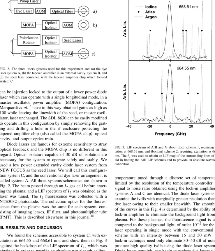
We found the schemes accessible to system C, with ex-citation at 664.55 and 668.61 nm, and show them in Fig. 3
against the backdrop of the LIF spectrum of I2, which was
obtained in order to provide an absolute wavelength
calibra-tion. We were happy to find that LIF I2spectrum had a much
higher signal to noise ratio than that available in a commonly
used atlas of I2 obtained by absorption spectroscopy,24
al-though the regions surrounding 668.61 and 664.55 nm have relatively few identified absorption lines. The diode laser system C performed just as well as the dye laser system for the plasmas in our experiment. Ion velocity space distribu-tion funcdistribu-tions obtained for each system are compared in Fig. 4. Both the dye laser and the diode seed laser were continu-ously tuned while the stand alone tapered amplifier chip was
temperature tuned through a discrete set of temperatures, limited by the resolution of the temperature controller. The signal to noise ratio obtained using the lock-in amplifier for systems A and C are identical. The diode laser systems can examine the ivdfs with marginally greater resolution than the dye laser owing to their smaller linewidth. The smoothness of the curves in this Fig. 4 is determined by the ability of the lock-in amplifier to eliminate the background light from the plasma. For these plasmas, the fluorescence signal is small
compared to the background light, of order 1022for the dye
laser operating in single mode with the conventional LIF scheme with an intensity between 15 and 30 mW. The lock-in technique need only eliminate 30–40 dB of noise to produce high quality ivdfs using the diode laser system C. Diode lasers certainly can begin to replace dye lasers where suitable absorption lines exist in the analyte ion.
The distribution function as produced by system B is inferior to the other two systems. This does not have any-thing to do with the linewidth of lasing modes, which are also very narrow for the MOPA acting as a stand alone diode laser, but stems from the multimode output of the laser. It was difficult to obtain a stable mode structure as the laser tuned. There was a fair amount of mode hopping. In Fig. 5, the mode spectra of the diode laser systems are compared. The modulation of the cavity modes due to the finite width of
FIG. 2. The three lasers systems used for this experiment are:~a!the dye laser system A,~b!the tapered amplifier in an external cavity, system B, and
~c!the seed laser combined with the tapered amplifier chip which formed system C.
FIG. 3. LIF spectrum of ArII and I2about~top!scheme 1, requiring
exci-tation at 668.61 nm, and~bottom!scheme 2, requiring excitation at 664.55 nm. The I2was used to obtain an LIF map of the surrounding lines of I2to
aid in finding the ArII LIF schemes and to provide an absolute wavelength calibration.
the chip serve to reduce the number modes to actually pro-duce fluorescence to just a few for system B, but there is a significant amount of power in laser lines detuned from the target line. Using the tapered amplifier chip injection locked to a low power, single mode seed laser gave the highest quality results of the two diode laser systems.
Tuning the seed laser was accomplished by ramping the
voltage of a PZT wafer, controlled with~GPIB!. A complete
scan for the LIF schemes 2 and 3 can be accomplished by tuning through 80 GHz, which corresponds to roughly 15 ion temperatures at 1 eV, and could be done in about 5 s. A family of ivdfs obtained in this fashion is shown in Fig. 6. Each curve corresponds to a different incident laser intensity spanning the range from 5 to 100 mW for this particular data set. We varied the forward current through the tapered am-plifier chip rather than the power of the seed laser. The seed
laser wavelength tunes slightly when its power is changed, a
common feature of diode lasers. Marquardt15has shown that
this particular tapered amplifier chip saturates at about 500 mW for an input seed laser intensity between 2 and 3 mW when the forward current through the chip is near its maxi-mum value of 2.2 A. Once one tunes to the line, obtaining ivdfs is a turn-key operation. One can shut the laser off and come back the next day and find the laser still tuned to the line! There is no need to rehearse what is true of dye laser systems. Tuning the diode laser, however, can lead to un-wanted shifts in the output intensity if the seed laser tunes through a maximum of a chip mode of the MOPA laser. But this is a problem only if the MOPA is operated near its power limit, otherwise the constant power feature of the MOPA current controller works well.
We found that the LIF signal strength varied quadrati-cally with input laser power at 668.61 nm, with system C, as
shown in Fig. 7~a!. This is as expected when the incident
intensity is such that the stimulated emission is significant compared with optical pumping, or the total spontaneous emission rate to the other states. The saturation intensity as given by Isat58phc 2 l21 5 (jA2 j A2 j dl,
is about 0.1 mW/mm2at 668 nm and a linewidth of 100 kHz
well below the spectral intensities used in our experiments with laser system C, and thus consistent with our results. We observe that the power broadening of the ivdf, shown in Fig. 7~b!, is still fairly weak. There are therefore competing ef-fects evidenced here. The relatively narrow linewidth avail-able in diode laser systems serve to modestly increase veloc-ity space resolution, while the need for reasonable signal to noise ratio implies a modest power broadening, and therefore a modestly reduced velocity space resolution.
Given that the LIF signal is proportional to the meta-stable state density
Ilif}n Pll3A23b
E
g~n!dn⇒n}Vac
Pll3A23b
,
FIG. 4. A comparison of ivdfs obtained by ~top!our dye laser system, system A,~center!system B, and~bottom!system C, the diode laser sys-tems. For system B, tuning was accomplished by changing the temperature of the chip, which had a resolution of 0.1 °C.
FIG. 5. A comparison of the mode structure of the diode laser systems: the top curve is the broadband MOPA chip output, system B, and the bottom curve is the seed laser plus MOPA chip, system C.
FIG. 6. A family of ivdfs obtain from system C by varying the output intensity; the values of which were in ascending order: 5.55, 11.13, 16.74, 33.18, 44.46, 67.92, 81.24, and 108.6 mW, respectively.
where the Vacis the voltage measured using a lock-in
ampli-fier, the light signal in phase with a 50% duty cycle
modu-lation of the beam, A23, and b are the atomic transition
probability of the fluorescent transition and the branching
ratio, respectively, and Pl is the input laser intensity, we
found that nF7/2/nG9/2'0.1, and nF7/2/nF9/2'1. The first
ra-tio gives the rara-tio of the metastable state populara-tion of an
alternative LIF scheme~664.55 nm excitation!to the
meta-stable state population of the commonly used one ~611.66
nm excitation!. This ratio involves LIF measurements with
different interference filters and thus the inference is indirect. We believe that the alternative metastable state is less well populated than the standard one in the UCI plasma, but the gap is not very wide, perhaps one order of magnitude differ-ence or less. The second ratio given above shows that the metastable state densities for alternative schemes 2 and 3 are essentially unity, and the inference is direct, since the optics train for the fluorescence measurement is identical for both measurements.
ACKNOWLEDGMENTS
This work was supported by NSF Grant No. 94-19192,
and one of the authors ~G.D.S.! wishes to acknowledge a
Faculty Research Grant from the University of San Diego.
1J. Camparo, Contemp. Phys. 26, 443~1985!. 2
C. Wieman and L. Hollberg, Rev. Sci. Instrum. 62, 1~1991!.
3
R. Fox, C. Weimer, L. Hollberg, and G. Turk, Spectrochimica Acta Rev. 15, 291~1993!.
4J. Franzke, A. Schnell, and K. Niemax, Spectrochimica Acta Rev. 15, 379 ~1993!.
5N. Uzelac and F. Leis, Spectrochimica Acta 47, 877~1992!. 6
R. Stern and J. Johnson, Phys. Rev. Lett. 34, 1548~1975!.
7D. Hill, S. Fornaca, and M. Wickham, Rev. Sci. Instrum. 54, 309~1983!. 8F. Anderegg et al., Phys. Rev. Lett. 57, 329~1986!.
9I. Hutchinson, Principles of Plasma Diagnostics~Cambridge University
Press, Cambridge, 1987!, p. 79ff.
10
M. Goeckner, J. Goree, and T. Sheridan, Phys. Fluids B 3, 2913~1991!.
11
The comparison we are thinking of is between two systems that can be tuned with an external voltage ramp, that do not make use of external reference cavities. The diode laser system~tunable low power diode laser system, e.g., NEW FOCUS Vortex 6000 at $8000, MOPA laser, SDL 8630 at $18 000, Newport MOPA controller, Model 6000, at $5000, and two Optical Isolators, NEW FOCUS Model 5568 at $6000!is nominally $37 000. The dye laser system ~tunable ring dye laser, e.g., Coherent 899-05 at $76 000, ion argon pump laser, Coherent Innova TSM 15 at $80 000,!costs nominally $156 000, a factor of 4.2 greater. In addition, for the dye laser system, one must arrange for a heat exchanger and substantial electrical power which may increase that factor by quite a bit.
12
See diode laser reference guide on the web page of Thor Labs, Inc., http://www.thorlab.com/. Industry standard wavelengths in the red are 635, 650, 670, 675, 680, 685, and 690 nm. These are solitary diode lasers. Tuneable systems made from these fill in the gaps in this range.
13
R. Ludeke and E. Harris, Appl. Phys. Lett. 20, 499~1972!.
14
R. Fox, A. Zirbrov, and L. Hollberg, ‘‘Semiconductor Diode Lasers,’’ Vol. III of Methods of Experimental Physics, Atomic, Molecular, and
Optical Physics~Academic, New York, 1995!.
15
J. H. Marquardt, F. C. Cruz, M. Stephens, C. W. Oates, L. W. Hollberg, J. C. Bergquist, D. F. Welch, D. Mehuys, and S. Sanders, in Proceedings of
SPIE~Pergamon, New York, 1996!, Vol. 2834, p. 34.
16
J. Curry and F. Skiff, Phys. Rev. Lett. 74, 1767~1995!.
17J. McChesney, P. Bellan, and R. Stern, Phys. Fluids B 3, 3363~1991!. 18D. Edrich, R. McWilliams, and N. Wolf, Rev. Sci. Instrum. 72, 3460
~1996!.
19V. Vujnovic´ and W. L. Wiese, J. Phys. Ref. Data 21, 919~1992!. 20G. Norle´n, Phys. Scr. 8, 249~1973!.
21
B. E. Cherrington, Gaseous Electronics and Gas Lasers~Pergamon, New York, 1979!, p. 204.
22W. R. Bennet, Jr., P. K. G. N. Mercer, B. Wexler, and H. Hyman, Phys.
Rev. Lett. 17, 987~1966!.
23R. McWilliams and R. Platt, Phys. Rev. Lett. 56, 835~1986!.
24S. Gerstenkorn and P. Luc, Atlas Du Spectre D’absorption De La Mol-ecule D’iode~Editions Du Centre National De La Recherche Scientifique, Anatole, France, 1978!, pp. 10–16.
FIG. 7. The LIF signal depended quadratically on the incident laser intensity for system C~top!, consistent with our estimate of the saturation intensity of 668.61 nm. The ion temperature~bottom!shows the slight effects of power broadening. The ion temperature is from a Gaussian fit to the ivdf and is uncorrected for Zeeman splitting.