Selection and Sizing of Pressure Relief Valves
Copyright © 2005, 2008Randall W. Whitesides, P.E.
Outline/Scope/Introduction
Course Outline
1. Codes and Standards 2. Equation Nomenclature 3. Selection and Sizing 4. Summary
5. Additional Resources
6. Glossary* (see note on page 2) 7. References
Scope
There are numerous types of pressure relieving devices and systems, both re-closing and non re-closing (rupture discs). This course contains technical information limited to pressure relief valves. The primary purpose of a pressure relief valve is protection of life and property by venting fluid from pressurized equipment. Information contained in this course applies to the over-pressurization protection of pressure vessels, lines and systems. Rupture discs are covered in PDH-center course number M113.
The basic formulae and capacity correction factors contained in this course have been, for the most part, empirically developed over time within the valve industry. The material presented re-flects current and generally accepted engineering practice. Formulations in this course are consis-tent with the requirements of ASME Section VIII, Division 1, and API Recommended Practice 520.
Introduction
The function of a pressure relief valve is to protect pressure vessels, piping systems, and other equipment from pressures exceeding their design pressure by more than a fixed, predeter-mined amount. The permissible amount of accumulation is covered by various codes and is a func-tion of the type of equipment and the condifunc-tions causing the accumulafunc-tion.
*
It is not the purpose of a pressure relief valve to control or regulate the pressure in the vessel or system that the valve protects, and it does not take the place of a control or regulating valve.
The aim of safety systems in processing plants is to prevent damage to equipment, avoid in-jury to personnel and to eliminate any risks of compromising the welfare of the community at large and the environment. Proper sizing, selection, manufacture, assembly, test, installation, and mainte-nance of a pressure relief valve are critical to obtaining maximum protection.
Types, Design, and Construction
A pressure relief valve must be capable of operating at all times, especially during a period of power failure; therefore, the sole source of power for the pressure relief valve is the process fluid.
The pressure relief valve must open at a predetermined set pressure, flow a rated capacity at a specified overpressure, and close when the system pressure has returned to a safe level. Pressure relief valves must be designed with materials compatible with many process fluids from simple air and water to the most corrosive media. They must also be designed to operate in a consistently smooth manner on a variety of fluids and fluid phases. These design parameters lead to the wide ar-ray ar-ray of pressure relief valve products available in the market today.
NOTE:
For ease of learning, the student is encouraged to print the glossary near the end of the course and while studying, refer to the definitions of bold italicized words or phrases when they are first encountered.
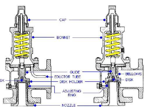
FIGURE 1 – TWO TYPES OF RELIEF VALVES
The standard design safety relief valve is spring loaded with an adjusting ring for obtaining the proper blowdown and is available with many optional accessories and design features. Refer to Figure 1 for cross-sectional views of typical valves. The bellows and balanced bellows design iso-late the process fluid from the bonnet, the spring, the stem, and the stem bushing with a bellows ele-ment. Jacketed valve bodies are available for applications requiring steam or heat transfer mediums to maintain viscosity or prevent freezing. Pilot-operated valves are available with the set pressure and blowdown control located in a separate control pilot. This type of valve uses the line pressure through the control pilot to the piston in the main relief valve and thereby maintains a high degree of tightness, especially as the set pressure is being approached. Another feature of the pilot-operat-ed valve is that it will permit a blowdown as low as 2 percent. The disadvantage of this type of valve is its vulnerability to contamination from foreign matter in the fluid stream.
Codes and Standards
Introduction
Since pressure relief valves are safety devices, there are many Codes and Standards in place to control their design and application. The purpose of this section of the course is to familiarize the student with and provide a brief introduction to some of the Codes and Standards which govern the design and use of pressure relief valves. While this course scope is limited to ASME Section VIII, Division 1, the other Sections of the Code that have specific pressure relief valve requirements are listed below. The portions of the Code that are within the scope of this course are indicated in red:
List of Code Sections Pertaining to Pressure Relief Valves
Section I Power Boilers
Section III, Division 1 Nuclear Power Plant Components
Section IV Heating Boilers
Section VI Recommended Rules for the Care and Operation of Heating Boilers Section VII Recommended Rules for the Care of Power Boilers
Section VIII, Division 1 Pressure Vessels
Appendix 11 Capacity Conversions for Safety Valves Appendix M Installation and Operation
Section VIII, Division 2 Pressure Vessels - Alternative Rules B31.3, Chapter II, Part 3 Power Piping - Safety and Relief Valves B31.3, Chapter II, Part 6 Power Piping - Pressure Relief Piping
ASME specifically states in Section VIII, Division 1, paragraph UG-125 (a):
“All pressure vessels within the scope of this division, irrespective of size or pressure, shall be provided with pressure relief devices in accordance with the requirements of UG-125 through UG-137.”
Reference is made to the ASME Boiler and Pressure Vessel Code, Section VIII, Division 1. The in-formation in this course is NOT to be used for the application of overpressurization protection to power boilers and nuclear power plant components that are addressed in the Code in Section I and Section III respectively. The student should understand that the standards listed here are not all in-clusive and that there exists specific standards for the storage of chlorine, ammonia, compressed gas cylinders, and the operation of refrigeration units, among probable others.
A Brief History of the ASME Code
Many states began to enact rules and regulations re-garding the construction of steam boilers and pressure vessels following several catastrophic accidents that occurred at the turn of the twentieth century that resulted in large loss of life. By 1911 it was apparent to manufacturers and users of boilers and pressure vessels that the lack of uniformity in these regula-tions between states made it difficult to construct vessels for interstate commerce. A group of these interested parties ap-pealed to the Council of the American Society of Mechanical Engineers to assist in the formulation of standard specifications for steam boilers and pressure vessels. (The American Society of Mechanical Engineers was organized in 1880 as an
educa-tional and technical society of Mechanical Engineers). After years of development and public com-ment the first edition of the code, ASME Rules of Construction of Stationary Boilers and for Allow-able Working Pressures, was published in 1914 and formally adopted in the spring of 1915. From this simple beginning the code has now evolved into the present eleven section document, with mul-tiple subdivisions, parts, subsections, and mandatory and non-mandatory appendices.
The ASME Code Symbol Stamp and the letters “UV” on a pressure relief valve in-dicate that the valve has been manufactured in accordance with a controlled quality assurance program, and that the relieving capacity has been certified by a designat-ed agency, such as the National Board of Boiler and Pressure Vessel Inspectors. The Code stamp shown is copyright The American Society of Mechanical Engineers.
The Universal Acceptance of the ASME Code
The ASME Boiler and Pressure Vessel Code enjoys widespread acceptance and is by adop-tion, to varying degrees, a legal document in all national and many international jurisdictions. The student should consult with local regulatory authorities, e.g. state agencies, to determine any spe-cialized jurisdictional requirements for pressure relief valves that may be applicable.
Equation Nomenclature
Unless otherwise noted, all symbols used in this course are defined as follows: A = Valve effective orifice area, in².
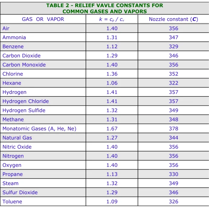
C = Flow constant determined by the ratio of specific heats (k), see Table 2 on page 20 (use C = 315 if k is unknown).
G = Specific gravity referred to water = 1.0 at 70° F
K = Coefficient of discharge obtainable from valve manufacturer (K = 0.975 for many nozzle-type valves)
Kb = Correction factor due to back pressure. This is valve specific; refer to manufacturer’s literature.
Kn = Correction factor for saturated steam at set pressures > 1,500 psia, see Equation 6 Kp = Correction factor for relieving capacity verses. lift for relief valves in liquid service, see Equations 1 and 2
Ksh = Correction factor due to the degree of superheat in steam (Ksh = 1.0 for saturated steam) Kv = Correction factor for viscosity, see Equations 8 & 9 (use Kv = 1.0 for all but highly viscous liquids)
Kw = Correction factor due to back pressure for use with balanced bellows valves M = Molecular weight
NRe = Reynolds number
P1 = Upstream pressure, psia (set pressure + overpressure + atmospheric pressure). (Sometimes referred to as actual relieving pressure)
ΔP = Differential pressure (set pressure minus back pressure, psig) Q = Flow, gpm
T = Inlet vapor temperature, °R (°F + 460) W = Flow, lb/hr
Z = Compressibility factor (use Z = 1 for ideal gas) µ = Liquid dynamic (absolute) viscosity, centipoise
Selection and Sizing
Introduction
Pressure relief valves must be selected by those who have complete knowledge of the pres-sure relieving requirements of the system to be protected and the environmental conditions particu-lar to that installation. Too often pressure relief valve sizes are determined by merely matching the size of an existing available vessel nozzle, or the size of an existing pipe line connection.
Correct and comprehensive pressure relief valve sizing is a complex multi-step process that should follow the following stepwise approach:
1. Each piece of equipment in a process should be evaluated for potential overpressurization scenarios.
2. An appropriate design basis must be established for each vessel. Choosing a design basis re-quires assessing alternative scenarios to find the credible worst case scenario.
3. The design basis is then used to calculate the required pressure relief valve size. If possible, the sizing calculations should use the most current methodologies incorporating such consid-erations as two-phase flow and exothermic reaction heat sources.
This course addresses pressure relief valves as individual components. Therefore, detailed design aspects pertaining to ancillary piping systems are not covered. Ancillary components are clearly noted in the course. These design issues can be addressed by piping analysis using standard accept-ed engineering principles; these are not within the scope of this course. Where relief device inlet and outlet piping are subject to important guidance by the ASME Code, it is so noted.
In order to properly select and size a pressure relief valve, the following information should be as-certained for each vessel or group of vessels which may be isolated by control or other valves. The data required to properly perform pressure relief valve sizing calculations is quite extensive.
1. The equipment dimensions and physical properties must be as-sembled. Modeling heat flow across the equipment surface re-quires knowledge of the vessel material’s heat capacity, thermal conductivity, and density (if vessel mass is determined indirectly from vessel dimensions and wall thickness).
2. The vessel geometry – vertical or horizontal cylinder, spherical, etc. – is a necessary parameter for calculating the wetted surface area, where the vessel contents contact vessel walls.
3. The properties of the vessel contents must be quantified. This in-cludes density, heat capacity, viscosity, and thermal conductivity. Values of each parameter are required for both liquid and vapor phases. Boiling points, vapor pressure, and volumetric thermal expansion coefficient values
NOTE:
A detailed example of analysis and selection methods of relief valve discharge pipe size based on pressure drop for two-phase flow can be found in PDHcenter.com course number M270, Selecting the Optimum Pipes Size.
also are required. Ideally, the properties will be expressed as functions of temperature, pres-sure, and compositions of the fluid.
Determination of the Worst-Case, Controlling Scenario
The most difficult aspect of the design and sizing of pressure relief valves is ascertaining the controlling cause of overpressurization. This is sometimes referred to as the worst case scenario. Overpressurization of equipment may result from a number of causes or combination of causes. Each cause must be investigated for its
magnitude and for the probability if its oc-currence with other events. The objective is to document which particular design ba-sis is the correct choice. The question that is begged: which scenario is the credible worst case? Among the techniques avail-able to solve this problem is fault-tree anal-ysis. A fault tree is a graphical representa-tion of the logical connecrepresenta-tions between ba-sic events (such as a pipe rupture or the failure of a pump or valve) and resulting events (such as an explosion, the liberation
of toxic chemicals, or over-pressurization in a process tank). A complete treatment of fault-tree the-ory and analysis is beyond the scope of this course.
Common Potential Overpressurization Scenarios
The usual causes of overpressurization and ways of translating their effects into pressure re-lief valve requirements are given in the following summarization. In most cases, the controlling overpressurization will be that resulting from external fire.
COMMON POTENTIAL OVERPRESSURIZATION SCENARIOS
1. External fire; 2. Blocked outlets
a. Blocked liquid outlet; b. Blocked vapor outlet; 3. Utility failures, including: a. General power failure; b. Partial power failure; c. Loss of instrument air; d. Loss of cooling water; e. Loss of steam;
f. Loss of fuel gas or fuel oil. 4. Loss of cooling duty, caused by: a. Loss of quenching medium; b. Air cooled exchanger failure; c. Loss of cold feed;
d. Loss of top or intermediate reflux. 5. Thermal expansion;
6. Abnormal heat input; 7. Abnormal vapor input; 8. Loss of absorbent flow; 9. Entrance of volatile material; 10. Accumulation of non-condensables; 11. Valve malfunction, such as;
a. Check valve malfunction;
b. Inadvertent valve operation (open/close/bypass); c. Control valve failure fully open;
d. Control valve failure fully closed. 12. Process control failure;
13. Mechanical equipment failure; 14. Exchanger tube rupture; 15. Upstream pressure relief; 16. Runaway chemical reaction; 17. Human error.
Pressure relief valves must have sufficient capacity when fully opened to limit the maximum pressure within the vessel to 110% of the maximum allowable working pressure (MAWP). This incremental pres-sure increase is called the prespres-sure accumulation. However, if the overpressurization is caused by fire or other external heat, the accumulation must not exceed 21% of the MAWP. Section VIII does not outline a detailed method to determine required relieving
ca-pacity in the case of external fire. Appendix M-14 of the Code recommends that the methods out-lined in API Recommended Practice 520 (Reference 3) be employed. The student is directed to Reference 7 for an excellent treatment, including examples, of the methodology of Reference 3.
Selecting the Set Point Pressure
Process equipment should be designed for pressures sufficiently higher than the actual work-ing pressure to allow for pressure fluctuations and normal operatwork-ing pressure peaks. In order that process equipment is not damaged or ruptured by pressures in excess of the design pressure, pres-sure relief valves are installed to protect the equipment. The design prespres-sure of a prespres-sure vessel is the value obtained after adding a margin to the most severe pressure expected during the normal op-eration at a coincident temperature. Depending on the situation, this margin might typically be the maximum of 25 psig or 10%.
The set point of a pressure relief valve is typically determined by the MAWP. The set point of the relief device should be set at or below this point. When the pressure relief valve to be used has a set pressure below 30 psig, the ASME Code specifies a maximum allowable overpressure of 3 psi. Pressure relief valves must start to open at or below the maximum allowable working pressure of the equipment. When multiple pressure relief valves are used in parallel, one valve shall be set at or below the MAWP and the remaining valve(s) may be set up to 5% over the MAWP. When sizing for multiple valve applications, the total required relief area is calculated on an overpressure of 16% or 4 psi, whichever is greater.
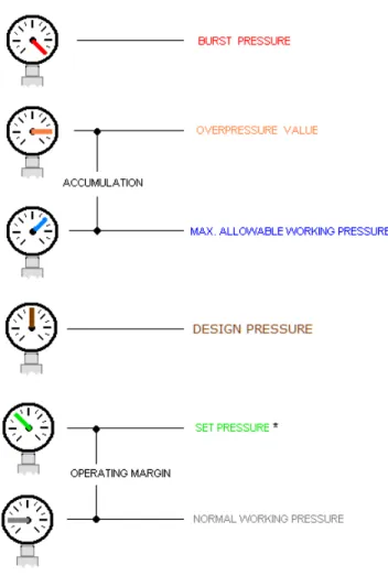
FIGURE 2 – HIERARCHY OF PRESSURE VALUES POINT OF CLARIFICATION
Much confusion often prevails because there are so many possible pressure values that simultaneously exist for a given process and pressure relief valve application. It may help to view these values graphically. Look at the illustration below. The pressures are arranged in ascending value from bottom to top.
Back Pressure Considerations
Back pressure in the downstream piping affects the standard type of pressure relief valve. Variable built-up back pressure should not be permitted to exceed 10% of the valve set pressure. This variable back-pressure exerts its force on the topside of the disc holder over an area approxi-mately equal to the seat area. This force plus the force of the valve spring, when greater that the ki-netic force of the discharge flow, will cause the valve to close. The valve then pops open as the static pressure increases, only to close again. As this cycle is repeated, severe chattering may re-sult, with consequent damage to the valve.
Conventional pressure relief valves are used when the back pressure is less than 10%. When it is known that the superimposed back pressure will be constant, a conventional valve may be used. If the back pressure percentage is between 10 to 40, a balanced bellow safety valve is used. Pilot operated pressure relief valves are normally used when the back pressure is more than 40% of the set pressure or the operating pressure is close to the pressure relief valve set pressure.
If back pressure on valves in gas and vapor service exceeds the critical flow pressure value of,
the flow correction factorKb must be applied. If the back pressure is less than the critical flow pres-sure, no correction factor is generally required.
IMPORTANT CONSIDERATION
Static pressure in the relief valve discharge line must be taken into consideration when determining the set pressure. If a constant static back-pressure is greater than atmospheric, the set back-pressure of the back-pressure relief valve should be equal to the process theoretical set pressure minus the static pressure in the discharge piping.
1 / 1 1 2 k k k P
%overpressure
0.073
%overpressure
0.016 0014 . 0 2 p KImpact of Overpressure in Liquid Service
The back pressure correction factor Kb just cited should not be confused with the correction factor Kp that accounts for the variation in relieving capacity of relief valves in liquid service that occurs with the change in the amount of overpressure. Typical values of Kp range from 0.3 for an overpressure of 0%, 1.0 for 25%, and up to 1.1 for an overpressure of 50%. A regression analysis by Whitesides on a typical manufacturer’s performance data produced the following correlation equations for Kp: For % overpressure < 25, [1] For % overpressure 25 → 50,
Kp 0 00335. %overpressure 0 918. [2]Finding the Effective Orifice Area
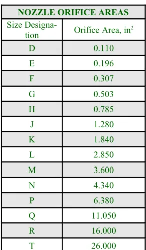
Once the pressure and rate of relief have been established for a particular vessel or pipeline, the required size of the pressure relief valve orifice, or the effective area, can be determined. Sizing formulae in this course can be used to calculate the required effective area of a pressure relief valve that will flow the required volume of system fluid at anticipated relieving conditions. The appropri-ate valve size and style may then be selected having an actual discharge area equal to or greappropri-ater that the calculated required effective area. The industry has standardized on valve orifice sizes and has identified them with letters from D through T having areas of 0.110 in2 through 26.0 in2 respec-tively. The standard nozzle orifice designations and their corresponding discharge areas are given in Table 1.
NOZZLE ORIFICE AREAS Size
Designa-tion Orifice Area, in2
D 0.110 E 0.196 F 0.307 G 0.503 H 0.785 J 1.280 K 1.840 L 2.850 M 3.600 N 4.340 P 6.380 Q 11.050 R 16.000 T 26.000
TABLE 1 – STANDARD NOZZLE ORIFICE DATA
There are a number of alternative methods to arrive at the proper size. If the process fluid application is steam, air, or water and the pressure relief valve discharges to atmosphere, manufac-turer’s literature can be consulted. These publications contain capacity tables for the manufacturer’-s varioumanufacturer’-s valvemanufacturer’-s for the fluidmanufacturer’-s jumanufacturer’-st mentioned at limanufacturer’-sted manufacturer’-set premanufacturer’-smanufacturer’-suremanufacturer’-s plumanufacturer’-s manufacturer’-several overpremanufacturer’-smanufacturer’-sure valuemanufacturer’-s. Given the large quantity of tables usually presented, caution must be exercised to use the proper ta-ble. With careful consideration, the tables’ usefulness can be expanded by making the proper ad-justments via correction factors for specific heat ratio, temperature, molecular weight, specific grav-ity, inlet and outlet piping frictional pressure losses, and fluid viscosity. This extrapolation of the standard tables is not recommended by this writer.
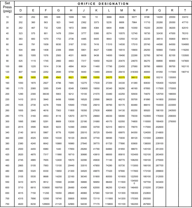
EXAMPLE 1 Steam Application Given:
Fluid: Saturated steam
Required Capacity: 40,000 lb/hr
Set Pressure: 140 psig
Overpressure: 10% (or 14 psig)
Back Pressure: Atmospheric
Inlet relieving Temperature: Saturation temperature
Molecular Weight: 18
Find: XYZ Valve Company’s standard orifice for this application.
Solution: Refer to Figure 3 on page 17 and find that a “P” orifice is required, which will have a ca-pacity of 53,820 lb/hr.
Most major pressure relief valve manufacturers also offer sizing software. While not an en-dorsement, two such products are SizeMaster Mark IV by Farris Engineering and Safety Size 2004 by Tyco Flow Control Americas. Pressure relief valve sizing software is unlimited in its capability to accept wide variability in fluid properties and is therefore extremely versatile.
When standard tables are not applicable or software is not available, the Engineer is relegat-ed to manual calculation to determine size. The requirrelegat-ed orifice size (effective area) may be calcu-lated with the following formulas:
Vapor or gases, A W T Z CK P Kb M 1 [3] Steam, A W P K K Kn sh 515. 1 [4]
FIGURE 3 – TYPICAL CAPACITY TABLE FROM THE XYZ RELIEF VALVE COMPANY
Capacity in Pounds per Hour of Saturated Steam at Set Pressure Plus 10% Overpressure
Set Press (psig) O R I F I C E D E S I G N A T I O N D E F G H J K L M N P Q R T 10 141 252 395 646 1009 165 10 3666 4626 5577 8198 14200 20550 33410 20 202 360 563 923 1440 2362 3373 5235 6606 7964 11710 20280 29350 47710 30 262 467 732 1200 1872 3069 4384 6804 8586 10350 15220 26350 38200 62010 40 323 575 901 1476 2304 3777 5395 8374 10570 12740 18730 32430 47000 76310 50 383 683 1070 1753 2736 4485 6405 9943 12550 15120 22230 38510 55800 90610 60 444 791 1939 9030 3167 5193 7416 11510 14530 17510 25740 44590 64550 104900 70 504 899 1408 2306 3599 5901 8427 13080 16510 19900 29250 50660 73400 119200 80 565 1005 1576 2583 4031 6609 9438 14650 18490 22290 32760 56740 82100 133500 90 625 1115 1745 2860 4463 7317 10450 16220 20470 24670 36270 69890 90900 147800 100 686 1220 1914 3136 4894 8024 11460 17790 22450 27060 39780 68900 99700 162110 120 807 1440 2252 2690 5758 9440 13480 20930 26410 318300 46800 81050 117000 190710 140 998 1655 2590 4943 6621 10860 15550 24070 30370 36610 53290 93210 135000 160 1050 1870 2927 4796 7485 12270 17530 27200 34330 41380 60830 105400 152500 180 1170 2085 3265 5349 8348 136900 19550 30340 38290 46160 67850 117500 170000 200 1290 2300 36030 5903 9212 15100 21570 33480 42250 50930 74870 129700 188000 220 1410 2515 3940 6456 10080 16520 23590 36620 46210 55700 81890 141800 205500 240 1535 2730 4278 7009 10940 17930 25610 39760 50170 60480 88910 154000 223000 260 1655 2945 4616 7563 11800 19350 27630 49890 54130 65250 95920 166100 240500 280 1775 3160 4953 8116 12670 20770 29660 46030 58090 70030 102900 178300 258000 300 1895 3380 5291 8669 13530 22180 31680 49170 62050 74800 110000 190400 276000 320 2015 3595 5629 9223 14390 23600 33700 52310 66010 79570 117000 202600 340 2140 3810 5967 9776 15260 25010 35720 55450 69970 84350 124000 214800 360 2260 4025 6304 10330 16120 26430 37740 58590 73930 89120 131000 226900 380 2380 4240 6642 10880 16980 27840 39770 61720 77890 93900 138000 239100 400 2500 4455 6980 1440 17850 29260 41790 64860 81850 98670 145100 251200 420 2620 4670 7317 11990 18710 30680 43810 68000 85810 103400 152100 263400 440 2745 4885 7655 12400 19570 32090 45830 71140 89770 108200 159100 275500 460 2865 5105 7993 13100 20440 33510 47850 74280 93730 113000 166100 287700 480 2985 5320 8330 13650 21300 34920 49870 77420 97690 117800 173100 299800 500 3105 5535 8668 14200 22160 36340 51900 80550 101600 122500 180100 312000 550 3410 6075 9512 15590 24390 39880 56950 88400 111500 1345000 197700 343400 600 3710 6610 103600 169700 26480 43490 62000 96250 121400 146400 215200 372800 650 4015 7150 11200 18350 28640 46960 67060 104100 131300 158300 232800 700 4315 7690 12050 19740 30800 50500 72110 111900 141200 170300 250300 750 4620 8230 128900 21120 32960 54030 77170 119800 151100 182200 267900
Liquids,
A Q G
K K Kp w v P
27 2. [5]
Manufacturer’s customized versions of Equation 5 should be used when available. These typically modify the equation presented to reflect actual coefficients of discharge (Kd) based on re-quired ASME capacity certification testing. In some cases, the variable Kp may be absent. The gas and vapor formula presented as Equation 3 is based on perfect gas laws. Many real gases and va-pors, however, deviate from a perfect gas. The compressibility factor Z is used to compensate for the deviations of real gases from the ideal gas. In the event the compressibility factor for a gas or vapor cannot be determined, a conservative value of Z = 1 is commonly used. Values of Z based on temperature and pressure considerations are available in the open literature.
The standard equations listed above may not fully take into consideration the effect of back pressure on the valve capacity. As previously stated, the capacity of pressure relief valves of con-ventional design will be markedly reduced if the back pressure is greater than 10% of the set pres-sure. For example, a back pressure of 15% of the set pressure may reduce the capacity as much as 40%. The capacities of bellows valves with balanced discs are not affected by back pressure until it reaches 40 to 50% of the set pressure.
Equation 4 is based on the empirical Napier formula for steam flow. Correction factors are included to account for the effects of superheat, back pressure and sub-critical flow. An additional correction factor Knis required by ASME when relieving pressure (P1) is above 1,500 psia:
K P P n 01906 1000 0 2292 1061 1 1 . . [6]
EXAMPLE 2 Manual Calculation Verification of Example 1 Steam Application Given: Same conditions and fluid properties as Example 1
Find: The correct standard orifice size to meet the given requirements.
Solution:
Because the steam is saturated and the set pressure < 1,500 psia, Ksh = 1.0 and Kn = 1.0
Calculate an orifice effective area using Equation 4:
A W P K K Kn sh 515 40 000 515 140 14 14 7 0 975 10 10 4 72 1 . , . . . in 2
From Table 1 on page 15 find the smallest standard orifice designation that has an area equal to or greater than A.
Select a “P” orifice with an actual area equal to 6.38 in2.EXAMPLE 3 Gas/Vapor Application (see Table 2 on page 20)
Given:
Fluid: Saturated ammonia vapor (NH3)
Required Capacity: 15,000 lb/hr
Set Pressure: 325 psig (constant back pressure of 15 psig deducted)
Overpressure: 10%
Back Pressure: 15 psig (constant)
Inlet relieving Temperature: NH3 saturation temperature @ P1 (138F)
Molecular Weight: 17
Find: The correct standard orifice size to meet the given requirements.
Solution:
EXAMPLE 3 Gas/Vapor Application (continued from page 19)
Because the back pressure is < 40% of set pressure, assume Kb = 1.0
Assume that NH3 is an ideal gas, Z = 1.0
Since a coefficient of discharge is not given, assume K = 0.975TABLE 2 - RELIEF VAVLE CONSTANTS FOR COMMON GASES AND VAPORS
GAS OR VAPOR k = cp / cv Nozzle constant (C)
Air 1.40 356 Ammonia 1.31 347 Benzene 1.12 329 Carbon Dioxide 1.29 346 Carbon Monoxide 1.40 356 Chlorine 1.36 352 Hexane 1.06 322 Hydrogen 1.41 357 Hydrogen Chloride 1.41 357 Hydrogen Sulfide 1.32 349 Methane 1.31 348
Monatomic Gases (A, He, Ne) 1.67 378
Natural Gas 1.27 344 Nitric Oxide 1.40 356 Nitrogen 1.40 356 Oxygen 1.40 356 Propane 1.13 330 Steam 1.32 349 Sulfur Dioxide 1.29 346 Toluene 1.09 326
Calculate an orifice effective area using Equation 3:
A W T Z CK P Kb M 1 15 000 138 460 10 347 0 975 325 32 5 14 7 10 17 0 707 , . . . . in 2
From Table 1 on page 15 find the smallest standard orifice designation that is equal to or greater than A.
Select an “H” orifice with an actual area equal to 0.785 in2.Inlet and Outlet Piping Considerations
While the detailed design or stress analysis of the inlet and outlet piping of pressure relief valves is not within the scope of this course, some important considerations are worth mentioning:
Satisfactory operation of a pressure relief valve requires that it be mounted vertically, prefer-ably on a nozzle at the top of a vessel or on a tee connection on top of a pipeline. The minimum in-let piping size should be equal in size to the pressure relief valve; the length should be minimized to reduce pressure drop and bending moments resulting from the reaction thrust developed from the discharging fluid. A rule of thumb is to design the inlet piping such that the total pressure drop in the inlet piping does not exceed 3% of the valve set pressure. When a single pressure relief valve is installed to protect several vessels, the connecting piping between these vessels should be adequate in size to keep the pressure drop within these limits.
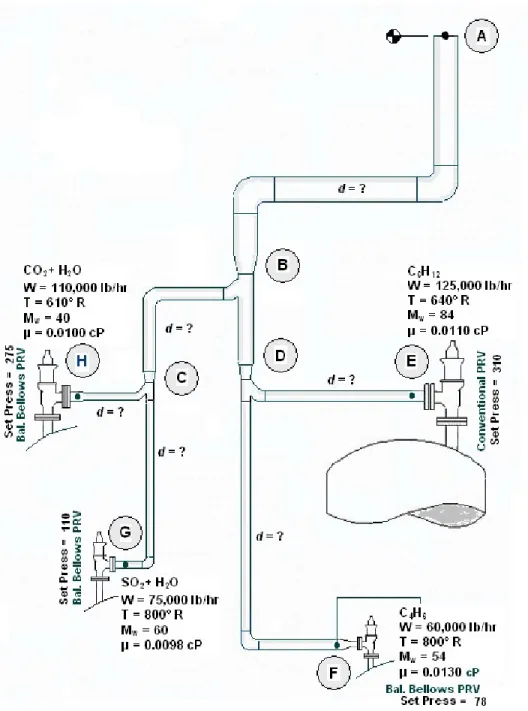
The type of discharge piping selected will depend largely on the hazardous nature of the ser-vice and on the value of the material that might be lost through a discharge event. For air or non-hazardous gas service, the discharge piping is normally directed vertically and extended such that it does not present a safety concern. Discharge elbows fitted with drain lines are normally used on steam and vapor services. The vapor discharge from these elbows is directed into a larger diameter riser pipe that is independently supported. The discharge piping should be extended vertically downward to a suitable drain for non-hazardous liquid service. A closed discharge piping system is required for hazardous services, or for services involving expensive chemicals. Collection systems for these categories of fluids may consist of a considerable quantity of piping with numerous pres-sure relief valves discharging into a common manifold (see Figure 4 below). The prespres-sure drop through this type of piping system must be calculated accurately, taking into consideration the fact
FIGURE 4 – TYPICAL RELIEF PIPING MANIFOLD
(Source: Fig.14a, page 63, PDHcenter.com course number M270)
The classical methods for pressure drop determination can be employed for both inlet and outlet piping arrangements. Values for the density, velocity, and viscosity of the discharging fluid should be based on the average pressure and temperature of the respective pipe component. The formation of hydrates, polymerization, and fluid solidification in pressure relief valve piping might
be an additional concern. A rule of thumb is to design the discharge piping such that the total pres-sure drop in the outlet piping does not exceed 10% of the valve set prespres-sure.
Supports for pressure relief valve piping should be designed to minimize the transference of pipe loads to the valve body. Allowance shall be made for piping expansion in cases of high tem-perature service; valve displacement due to thermal expansion may cause valve leakage or faulty operation. The internal pressure, dead loads, thermal expansions, reaction thrust, resulting dynamic forces, and resulting bending stresses due to discharging fluid will be exerted on the pressure relief valve inlet and outlet bends and elbows.
Additional considerations are:
1. Design discharge piping with clean-outs to preclude internal obstructions;
2. Test the piping hydrostatically to 150% of the maximum anticipated pressure of the dis-charge system;
3. Provide covers or caps to prevent the intrusion and accumulation of rain or the entrance of birds or rodents;
4. Design piping to be self-draining.
Viscous Fluid Considerations
The procedure to follow to correct for a viscous fluid, i.e. a fluid whose viscosity is greater than 150 centipoise (cP) is to:
1. Determine an initial trial required pressure relief valve orifice size (effective area) discount-ing any effects for viscosity. This is done by usdiscount-ing the standard liquid sizdiscount-ing formula and setting the viscosity correction factor Kv = 1.0. Select the standard orifice size letter
desig-nation that has an actual area equal to or greater than this effective area.
2. Use the actual area of the viscous trial size orifice selected in Step 1 to calculate a Reynolds number (NRe) using the following formula:
N G Q A
Re 2800
[7]
3. Use the Reynolds number calculated in Step 2 to calculate a viscosity correction factor Kv from the following equations:
For NRe < 200, Kv 0 27. lnNRe0 65. [8] For NRe 200 → 10,000
Kv 0 00777. lnNRe 2 0165. lnNRe 0128. [9]4. Determine a corrected required effective area of the pressure relief valve orifice using the standard liquid sizing formula and the value of Kv determined in Step 3.
5. Compare the corrected effective area determined in Step 4 with the chosen actual orifice area in Step 1. If the corrected effective area is less than the actual trial area assumed in Step 1, then the initial viscous trial size assumed in Step 1 is acceptable. Repeat this itera-tive process until an acceptable size is found.
EXAMPLE 4 Viscous Liquid Application Given:
Fluid: No. 6 Fuel Oil
Required Capacity: 1,200 gal/min
Set Pressure: 150 psig
Overpressure: 10%
Back Pressure: Atmospheric
Inlet relieving Temperature: 60° F Dynamic Viscosity: 850 cP Specific Gravity: 0.993
Solution:
Since the overpressure is < 25%, determine the correction factor Kp from Equation 1:
61 . 0 016 . 0 10 073 . 0 10 0014 . 0 016 . 0 re overpressu % 073 . 0 re overpressu % 0014 . 0 2 2 p p p K K K
Select an initial orifice size by setting Kv = 1.0 and using Equation 5. Since the back pressure = 0then Kw = 1.0:
A Q G K K Kp w v P 27 2 1 200 0 993 27 2 0 61 10 10 150 0 589 . , . . . . . . in 2
From Table 1 on page 15 it can be seen that an orifice size designation “P” with an actual area of 6.38 in2 must be used.
Using the trial “P” orifice area, calculate the Reynolds number using Equation 7:
N G Q A Re . . 2800 2800 0 993 1200 850 6 38 615
Since NRe > 200, use Equation 9 and compute a viscosity correction factor Kv:
K N N K K v v v 0 00777 0165 0128 0 00777 6 422 0165 6 422 0128 0 87 2 2 . ln . ln . . . . . . . Re Re
Compute a corrected orifice effective area based on the now known value of Kv:
A Q G K K Kp w v P 27 2 1 200 0 993 27 2 0 61 10 0 87 150 0 6 76 . , . . . . . . in 2
Since the corrected orifice effective area (6.76 in2) is greater than the selected trial orifice area (6.38 in2), the “P” orifice is unacceptable. Select the next larger size orifice (Q) with an area of 11.05 in2 for this viscous application.Two-Phase Flow Ramifications
In recent years, methodologies originally used to determine pressure relief valve orifice ar-eas have come under incrar-easing scrutiny. Research into current design codes and practices for pres-sure relief valves has shown that the commonly applied calculations methods may underestimate re-lief capacity. Newer more theoretically sound models are now being developed. Because flash-ing-liquid (two-phase) flow is so commonplace in the chemical process industries, this subject is at the forefront of the developmental effort.
The flow occurring in a pressure relief valve is complex. In order to select an appropriate model a number of factors such as flow patterns, phase distribution, flow conditions and fluid properties must be considered with respect to the nature of the fluid. There are a wide variety of theoreti-cal models which apply to two-phase flow. Each model has limitations and while a particular model may work well under certain conditions, it may not be applicable in others. In some special processes, it has even been determined that some two-phase flow is actually three phase, i.e. sol-id, liquid and gas, flow.
Because two phase flow generally has a decreased flow capacity compared to single phase flow, greater relief orifice area often is required for two-phase flow. Sizing technology that is no longer considered adequate or appropriate can be problematic. Oversizing can be as detrimental as undersizing. Oversizing a pressure relief valve with two-phase flow can have dangerous consequences. Excessive fluid flashing on the downstream side of an oversized pressure relief valve can cause the back pressure buildup to the point that the relief device function is impaired. The result could be a catastrophic vessel failure.
Recent research conducted by AIChE’s Design Institute for Emergency Relief Systems (DIERS) has indicated that the API method of sizing pressure relief valves for two-phase flow leads to undersized valves in comparison with homogenous equilibrium models (HEM) under certain conditions. The HEM treats the flashing two phase flow mixture much like a classical compressible
gas while undergoing an adiabatic expansion with thermodynamic equilibrium in both phases. The HEM yields conservative estimates of the flow capacity in a pressure relief valve.
Summary
The adequacy of any safety relief system is subject to certain conditions that are the princi-ple basis for the design. Determination of correct required relieving capacity is often times the most obtuse step in the design process. For this reason, knowledge of sophisticated failure probability and evaluation techniques such as fault-tree analysis are important in making correct decisions re-garding process upset severity. While the tired and true methods for
pressure relief valve sizing are probably adequate, and generally pro-duce conservative results, increased knowledge in the field of two phase hydraulics, highlighted by test work and information published by groups such as AIChE’s DIERS, should be considered in any de-sign of a pressure relief system.
Pressure relief valves should be designed to passively protect against a predetermined set of “worst case” conditions and should be installed to react to these conditions regardless of daily operation ac-tivities.
For each piece of equipment requiring overpressurization pro-tection, a credible worst-case scenario should be defined. For a given
vessel, several plausible scenarios may exist – from external fire to various operating contingencies, such as overfill or vessel swell conditions. System overpressurization is assumed to be caused by the controlling scenario. Most controlling scenarios are loaded with conservative assumptions that are never achieved in actual operating conditions. It is the controlling scenario relieving rate that dictates the pressure relief valve size. If sized correctly, the pressure relief valve should have enough discharge capacity to prevent the pressure in the pressure vessel rising 10% above its maxi-mum allowable working pressure.
In addition to liquids, the scope of this course has been limited to all vapor flow. It is appli-cable when it is known that only vapor will be present or when the liquid portion is assumed to completely flash. Where mixed flow is present, and the total mass quantity (flow rate) is known, an
all vapor model should yield conservative results. It may be prudent to be conservative given the uncertainly of two-phase prediction models.
Additional Resources
The student should read/review Reference 2 paragraphs UG-125 through UG-137 when de-signing pressure relief systems and selecting and sizing pressure relief valves.
The American Society of Mechanical Engineers American Petroleum Institute
Three Park Avenue 1220 L Street NW
New York, NY 10016-5990 Washington, DC 2005-4070
800-843-2763 (U.S/Canada) 202-682-8000
Email: CustomerCare@asme.org Website: www.api.org
Glossary
This section contains common and standard definitions related to pressure relief valves. It is in accordance with generally accepted terminology.
accumulation – a pressure increase over the maximum allowable working pressure (MAWP) of the equipment being protected, during discharge through the pressure relief valve, usually expressed as a percentage of MAWP. Compare with overpressure.
actual discharge area – the net area of a selected orifice which dictates the pressure relief valve re-lieving capacity.
back pressure – the static pressure existing at the outlet of a pressure relief valve due to pressure in the discharge system.
balanced safety relief valve – a pressure relief valve which incorporates means of minimizing the effect of back pressure on the operational characteristics (opening pressure, closing pressure, and re-lieving capacity).
blowdown – the difference between actual lifting pressure of a pressure relief valve and actual re-seating pressure expressed as a percentage of set pressure.
blowdown pressure – the value of decreasing inlet static pressure at which no further discharge is detected at the outlet of a pressure relief valve after the valve has been subjected to a pressure equal to or above the lifting pressure.
built-up back pressure – pressure existing at the outlet of a pressure relief valve caused by the flow through that particular valve into a discharge system.
chatter – abnormal rapid reciprocating motion of the movable parts of a pressure relief valve in which the disc contacts the seat.
closing pressure – the value of decreasing inlet static pressure at which the valve disc reestablishes contact with the seat or at which lift become zero.
coefficient of discharge – the ratio of the measured relieving capacity to the theoretical relieving capacity.
constant back pressure – a superimposed back pressure which is constant with time.
conventional safety relief valve – a pressure relief valve which has its spring housing vented to the discharge side of the valve. The operational characteristics (opening pressure, closing pressure, and relieving capacity) are directly affected by changes in the back pressure on the valve.
design pressure – the value selected for the design of equipment for the most severe condition of coincident pressure and temperature expected in normal operation, with provision for a suitable margin above these operating conditions to allow for operation of the pressure relief valve. The de-sign pressure usually becomes the maximum allowable working pressure.
discharge area – see actual discharge area.
effective discharge area – a computed area of flow through a pressure relief valve, contrasted to ac-tual discharge area. For use in recognized flow formulas to determine the required capacity of a pressure relief valve.
flow capacity – see rated relieving capacity.
flow-rating pressure – the inlet static pressure at which the relieving capacity of a pressure relief valve is measured.
inlet size – the nominal pipe size of the inlet of a pressure relief valve, unless otherwise designated.
maximum allowable working pressure – (1) the pressure determined by employing the allowable stress values of the materials used in the construction of the equipment. It is the least value of al-lowable pressure value found for any component part of a piece of equipment for a given tempera-ture. The equipment may not be operated above this pressure and consequently, it is the highest pressure at which the primary pressure relief valve is set to open. (2) the maximum gage pressure permissible at the top of a pressure vessel in its normal operating position at the designated coinci-dent temperature specified for that pressure.
nozzle constant, nozzle coefficient - a variable (C ) in the standard gas and vapor sizing formula which is dependent on the specific heat ratio of the fluid. See equation 3 and Table 2.
operating pressure – the service pressure to which a piece of equipment is usually subjected.
orifice area – see actual discharge area
outlet size – the nominal pipe size of the outlet of a pressure relief valve, unless otherwise designat-ed.
overpressure – a pressure increase over the set pressure of a pressure relief valve, usually expressed a percentage of set pressure. Compare with accumulation.
pilot-operated pressure relief valve – a pressure relief valve in which the major relieving device is combined with and is controlled by a self-actuated pressure relief valve.
pressure relief valve – a generic term for a re-closing spring loaded pressure relief device which is designed to open to relieve excess pressure until normal conditions have been restored.
rated relieving capacity – that portion of the measured relieving capacity permitted by the applica-ble code of regulation to be used as a basis for the application of a pressure relief valve.
relief valve – a pressure relief valve actuated by inlet static pressure and having a gradual lift gener-ally proportional to the increase in pressure over opening pressure. It is primarily used for liquid service.
relieving pressure – set pressure plus overpressure.
safety valve – a pressure relief valve actuated by inlet static pressure and characterized by rapid opening or pop action. It is normally used for steam and air service.
safety relief valve – a pressure relief valve characterized by rapid opening or pop action, or by opening in proportion to the increase in pressure over the opening pressure, depending on the appli-cation. It may be used in either liquid or compressible fluid applications based on configuration.
set pressure – the value of increasing inlet static pressure at which a pressure relief valve begins to open.
superimposed back pressure – the static pressure existing at the outlet of a pressure relief valve at the time the valve is required to operate. It is the result of pressure in the discharge system from other sources.
References
1. Department of Labor, Occupational Safety and Health Administration, Process Safety Management of Highly Hazardous Chemicals, 29 CFR 1910.119, February 24, 1992. 2. American Society of Mechanical Engineers, ASME Boiler and Pressure Vessel Code,
Section VIII, Pressure Vessels, Division 1, ASME, New York, 2001 plus addenda. 3. American Petroleum Institute, API Recommended Practice 520, Sizing, Selection, and
Installation of Pressure-Relieving Devices in Refineries, Part I, Sizing and Selection, API, Washington D.C., 2000.
4. Fisher, H.G., et al., Emergency Relief System Design Using DIERS Technology, AIChE’s Design Institute for Emergency Relief Systems, DIERS, AIChE, New York, 1992.
5. Quoc-Khanh, Tran and Reynolds, Melissa, Sizing of Relief Valves for Two-Phase Flow in the Bayer Process, Kaiser Engineers PTY Limited, Perth, Western Australia, 2002.
6. Hauptmanns, Ulrich and Yllera, Javier, Fault-tree Evaluation by Monte Carlo Simulation, Chemical Engineering magazine, January 10, 1983.
7. Crosby® Engineering Handbook Technical Publication No. TP-V300, Pressure Relief Valve Engineering Handbook, Crosby Valve Incorporated, Wrentham, MA, 1997.
8. The Crane Company Technical Paper No. 410, Flow of Fluids through Valves, Fittings, and Pipe, 25th printing, 1991.
9. Blackwell, Wayne W., Calculating Two-phase Pressure Drop, Chemical Engineering magazine, September 7, 1981, pp. 121-125.
10. Whitesides, Randall W., Selecting the Optimum Pipe Size, course number M270, PDHcenter.com, Herndon, VA., © 2008.