HAL Id: hal-02280474
https://hal-univ-rennes1.archives-ouvertes.fr/hal-02280474
Submitted on 14 Nov 2019HAL is a multi-disciplinary open access archive for the deposit and dissemination of sci-entific research documents, whether they are pub-lished or not. The documents may come from teaching and research institutions in France or abroad, or from public or private research centers.
L’archive ouverte pluridisciplinaire HAL, est destinée au dépôt et à la diffusion de documents scientifiques de niveau recherche, publiés ou non, émanant des établissements d’enseignement et de recherche français ou étrangers, des laboratoires publics ou privés.
Interfacial phenomena in optical fibre embedded systems
Irina Severin, Mihai Caramihai, Rochdi El Abdi, Marcel Poulain
To cite this version:
Irina Severin, Mihai Caramihai, Rochdi El Abdi, Marcel Poulain. Interfacial phenomena in optical fibre embedded systems. Composite Structures, Elsevier, 2019, 224, pp.111029. �10.1016/j.compstruct.2019.111029�. �hal-02280474�
Interfacial phenomena in optical fibre embedded systems
Irina SEVERIN
11, Mihai CARAMIHAI
1, Rochdi EL ABDI
2, Marcel POULAIN
3 1 University Politehnica of Bucharest, 313 Splaiul Independentei, 060042 Bucharest, Romania;[email protected]; [email protected]
2 University of Rennes 1, Campus Beaulieu, 35042 Rennes Cedex, France 3 Photonic Material Laboratory, University of Rennes 1, 35045 Rennes Cedex, France
Abstract: The reliability and the expected lifetime of optical fibres used in different structural applications, including composites are closely related to the chemical environment action on the silica cladding. To ensure the long-term mechanical strength of the optical fibres, a polymer coating was applied onto the fibre surface during fabrication. The aging mechanism is assumed to enlarge or to extend the "Griffith flaws" which are spread at the fibre surface. Systematic experiments have been carried out to assess different reagents’ effect on the fibre mechanical strength, such as fluorinated vapors, acetylene, ammonia and organic compounds. Different types of fibres, including hermetically coated ones, have been aged and subjected to mechanical tests under dynamic conditions. The Weibull statistical study allows to evaluate the flaws’ dispersion along the fibre surface. SEM observations evidenced several failure mechanisms.
Keywords
:
cladding-polymer coating interface, hermetical coating, dynamic testing, failure mechanismsINTRODUCTION
In numerous structural applications, optical fibre embedded composites based on polymeric matrices with glass or carbon reinforcements [1, 2] are recommended for structural health monitoring. Monitoring in real time the structural integrity using optical fibre sensors is linked with the strength transfer at the interface between the composite structure and the optical fibre [3, 4]. Despite the significant progress in fabrication technology, reliability of optical fibres for sensors and smart structures still appears as a major factor [5, 6]. As sensors based on optical fibres developed for working in different environments (spectroscopic gas sensors, analysis of smells, environmental evaluation, nuclear applications etc.) [7-14], studying the mechanical reliability in harsh chemical aging conditions appears relevant. In other applications, based on optical fibres embedded in composite systems, the optical surface integrity appears essential due to the potential damage during fabrication or in use.
This experimental investigation is aimed to compare the chemical reliability of silica optical fibres to a series of aggressive reagents in gaseous and liquid phase, such as fluorinated vapours, acetylene, ammonia (gaseous reagents) and dimethyl-sulfoxide (liquid reagent). Secondly, the study is aimed to
assess the effectiveness of the hermetical coating in-line deposition in terms of mechanical and chemical reliability.
EXPERIMENTAL PROCEDURE
Different types of silica optical fibers (SOF) are used for testing, as given in table 1. The difference lies in cost and performance. Based on previous experience, Verrillon fibers were used for investigating the chemical reliability to different reagents, while iX fiber and Alcatel (cheaper fibers) were tested mainly in order to be embedded in composites (glass fiber and epoxy matrix). The hermetically coated fibers (H SOF) were fabricated by Verrillon, Boston USA.
Table 1 Tested optical fibres Fiber Special treatment Cladding diameter, µm Coating diameter, µm
SOF Verrillon, Boston MA - 125 250 (Fig. 1)
SOF Verrillon, Boston MA carbon in line deposition (H SOF)
125 250
iX Fiber, Lannion, France
-80 80
172 101.8 (Fig. 2)
SOF Alcatel, France - 125 250
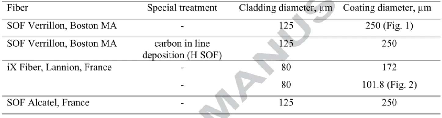
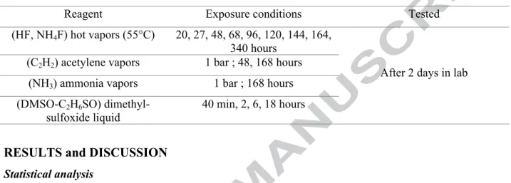
The silica cladding of 125 µm in diameter is protected with two layer epoxy-acrylate polymer coating of 250 µm in diameter (Fig. 1). Other fibers consist of silica cladding of 80 µm in diameter protected with one layer acrylate polymer of 101.8 µm in diameter (Fig. 2) or two layers of 172 µm in diameter. In order to protect the sensitive glass surface, the inner layer coating is soft, allowing to glue in some way the micro-cracks, to inhibit their evolution and to prevent water molecule reaction. In order to protect the fiber against external aggression, the external coating is hard, thus manipulation for testing or cabling is facilitated. Despite the balanced ratio of low cost and the good performance, the main limitation of the epoxy-acrylate coating (Mid-Term Dual Acrylate Enhanced Performance) lies in the high sensitivity to chemical reagents, including humidity. That’s why for specific applications, hermetic carbon coating (in our experimental campaign H SOF Verrillon) or inorganic ones may be applied acting as an efficient barrier against corrosive reagents.
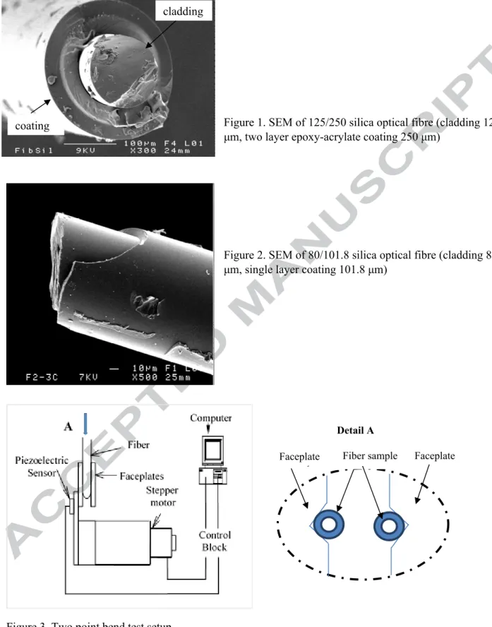
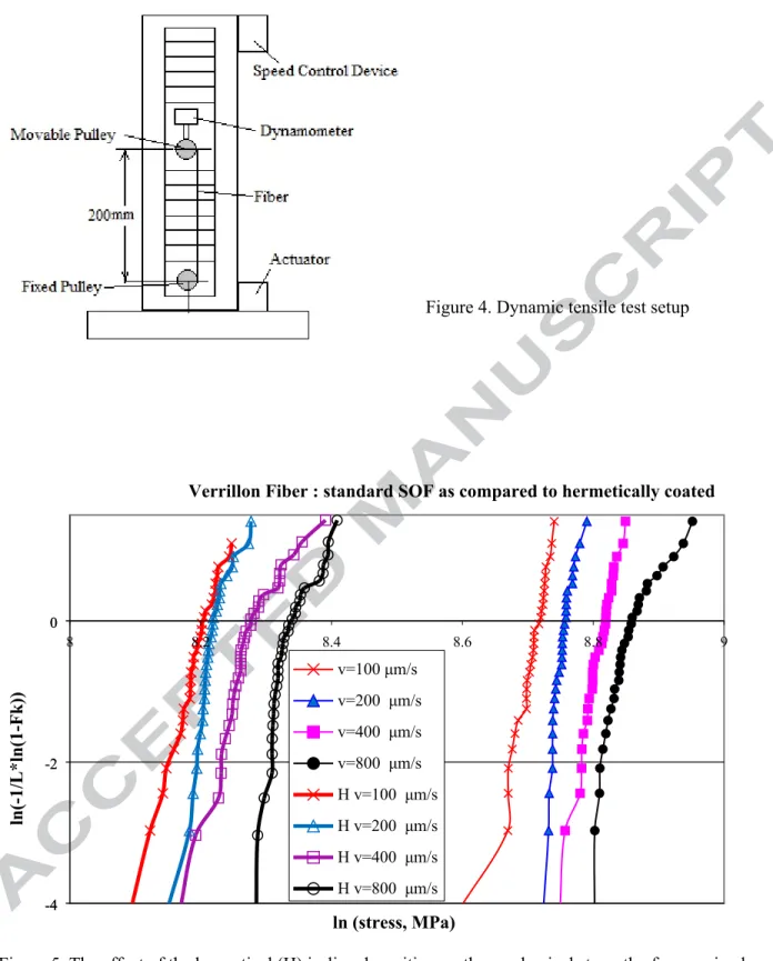
In line with the International Standard [15], dynamic testing was performed in controlled environment at 18°C (±2°C) temperature and 45% (±5%) relative humidity, using two different procedures: two point bending testing experimental bench (Fig. 3) and tensile testing bench Lloyds LR 50K (Fig. 4). Testing samples geometry is given in table 2. In both dynamic testing procedures, four different strain rates were applied and for each testing conditions series of 30 samples were registered. Then the Weibull plots were traced and, in several cases, the stress corrosion factor nd was calculated, too.
Table 2 Sample’s length
Two point bending testing Tensile testing
Optical fiber testing length 100 mm centrally placed between the faceplates
Optical fiber free testing length 200 mm
Fiber samples were subjected to harsh chemical environment, as given in table 3, then dynamically tested. Finally, their behavior was compared based on the mechanical testing results and the SEM investigations.
Table 3 Testing conditions
Reagent Exposure conditions Tested
(HF, NH4F) hot vapors (55°C) 20, 27, 48, 68, 96, 120, 144, 164, 340 hours
(C2H2) acetylene vapors 1 bar ; 48, 168 hours (NH3) ammonia vapors 1 bar ; 168 hours (DMSO-C2H6SO)
dimethyl-sulfoxide liquid
40 min, 2, 6, 18 hours
After 2 days in lab
RESULTS and DISCUSSION
Statistical analysisPrevious experiments [16] have revealed the polymer coating permeability and the subsequent aging sensitivity of the silica optical fibre. In order avoid hydrogen diffusion through the silica cladding surface, in the fabrication process, a thin layer of few hundred Å in thickness of diamond like carbon may be in-line deposited, followed by the subsequent polymer coating rapidly performed UV-polymerisation. The hermetical coating allows fibre reliability improvement.
The two point bending testing doesn’t replace the tensile testing as fiber strength measurement ; due to the small length fiber sample (10 cm) placed between the grooved faceplates (Fig. 3 detail A) and the short time necessary for testing manipulations, too, valuable information has been provided to compare defect size distribution and micro-cracks evolution [17].
The stress to fracture σ (in GPa) was calculated from the distance separating the faceplates at the fracture moment, using the Proctor and Mallinder relation, improved by Griffoen [18], as follows:
(1) 𝜎=𝐸.𝜀
(
1 +𝛼.𝜀2)
where E (=72 GPa) the silica Young modulus, α (=4.75) non-linearity elastic parameter, ɛ the strain in the fibre depending on the optical fibre geometry, given by the relation [18]:
(2) 𝜀= 1,198 𝑑𝑓
(
𝑑 ‒ 𝑑𝑐+ 2𝑑𝑔)
where df the fibre diameter (=250 μm), dcthe cladding diameter (=125 μm), d the distance between the faceplates at the fracture moment measured by the sensor, dgthe grooves depth (=0.2 mm).
The failure stress was registered for each sample, and then the results were statistically treated. In the case of brittle materials, such as silica optical fibers, the mechanical strength, determined from the fracture of the most critical flaw on fiber’s surface, presents a significant scattering. The statistical Weibull treatment is considered relevant [19, 20]. The Weibull law gives a relationship between the cumulative probability
FK (%) of fibre failure and the corresponding applied stress. The Weibull plot is given by the evolution of the logarithmic function of probability
(3) 𝑙𝑛
[
‒1 𝐿 ∗ 𝑙𝑛(
1‒ 𝐹𝐾)
]
where L is the sample length, according to the logarithmic function of the fracture stress (4) 𝑙𝑛[𝑠𝑡𝑟𝑒𝑠𝑠, 𝑀𝑃𝑎]
For each series of experiments (30 samples), the fracture stress is registered, the cumulative probability to fracture is calculated and the Weibull plot is traced. Interpolating the testing results, the linear distribution slope allows to evaluate the flaws size dispersion. Depending on these slopes, one or more defect populations are present. Usually, at low strain rates bi or multi modal Weibull distribution may be noticed, meaning that both extrinsic and intrinsic micro-cracks characterize the fiber failure. At high strain rates, usually a mono-modal distribution is expected, with a high slope, meaning that a single defect population initiated failure, respectively the intrinsic micro-cracks. Dust in fiber drawing tower or foreign particles in the coating material may be the origin of these intrinsic micro-flaws.
Effect of hermetic deposition
Presenting on the same graph the Weibull diagrams for Verrillon standard optical fibers (SOF) as compared to the Verrillon fiber with the hermetic in-line deposition (H SOF) (Fig. 5), following the improved fabrication technology, one may notice the similar behavior in terms of flaw size dispersion (Weibull plots with the similar slope), but a significant decrease of the mean stress. The results dispersion is broader for the extreme strain rates (100 and 800 μm/s) and slightly steeper for the median ones (200 and 400 μm/s). The median failure stress (the stress corresponding to the 50% failure probability FK) varied between 6 and 7 GPa for the standard SOF. In the case of non-aged (as-received) hermetical coated H SOF, the median failure stress decreased to 3.6 and 4.1 GPa.
The aging treatment in fluorinated vapors has revealed significant improvement following the carbon coating onto the silica surface. Two series of samples were prepared simultaneously. In a cylinder disposal, the samples were placed parallel to the cylinder height. The series placed in the disposal far from the vapor release were noted f and the second ones, placed close, were noted c. The exposure duration of vapor release varied from 20 hours to 14 days.
The fluorinated environment is very aggressive for silica. The Weibull diagrams for the standard silica optical fibers reveal the significant decrease of the fiber strength, losing up to ¾ of the as-received
strength (Fig. 6) together with a broader distribution (as compared to the as-received fibers), indicating the extension of extrinsic flaws. The standard SOF damaged extensively after 12 days of exposure with a difference of about 1 GPa between the two series, depending on the fibers’ position (f, c) in the cylinder disposal during the chemical aging.
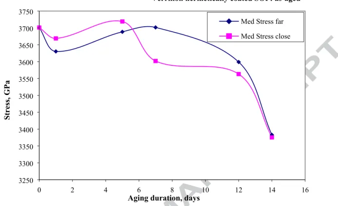
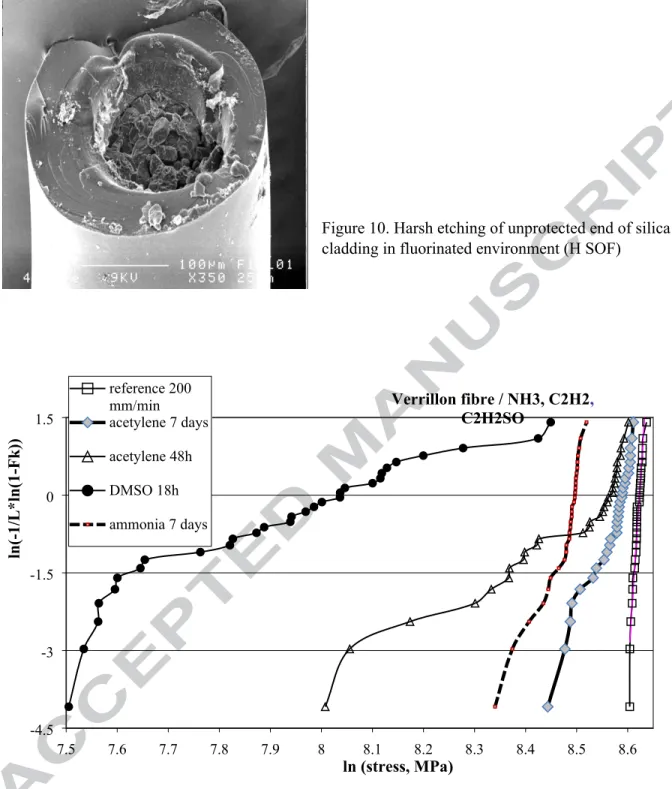
The SEM indicated numerous crystal deposits along the fiber independent of the sample position in the disposal (Fig. 7). The chemical analysis of crystal deposition revealed fluoride presence, but silicon too, concluding that silicon diffused from silica cladding and segregated in a solid phase generated from Si4F. Contrary to the lower mechanical strength of the as-received H SOF compared to the SOF, the hermetic deposition leads to an improved behaviour to the fluorinated environment, with a steady state until 12 days of exposure and starting to decrease from 14 days (Fig. 8). Even in these conditions the decrease is less than 10% of the initial strength, so as the hermetic deposition leads to resistance to chemical reagents. In Fig. 9, the Weibull diagrams are compared for the four strain rates corresponding to H SOF as-aged for long duration (14 days). One may suppose that the environment is saturated as the fiber’s mechanical behavior does not depend on the vapor release position. Unfortunately, the silica end exhibited catastrophic damage (Fig. 10) attributed to continuous etching. Once the process is initiated, the silica structure has been continuously destroyed. The carbon protection appears quite effective at the interface silica cladding – polymer coating, but if the reagent reaches the unprotected silica, the process appears irreversible and highly reactive.
Influence of chemical reagents
As-aged standard SOF behavior was investigated subjecting the fiber to gaseous reagents (C2H2, respectively NH3, both at 1 bar pressure); other series subjected the fiber soaking in liquid reagent C2H6SO, known as DMSO.
The aged samples were dynamically tensile tested, the stress to fracture was registered and Weibull plots were produced as previously discussed (Fig. 11).
Comparing the results distribution of the reference fiber (as-received) with the as-aged ones in different reagents, the effect appears obvious with a transition from steeper (as received) to broader (as-aged) aspect; the mechanical strength decreases, too.
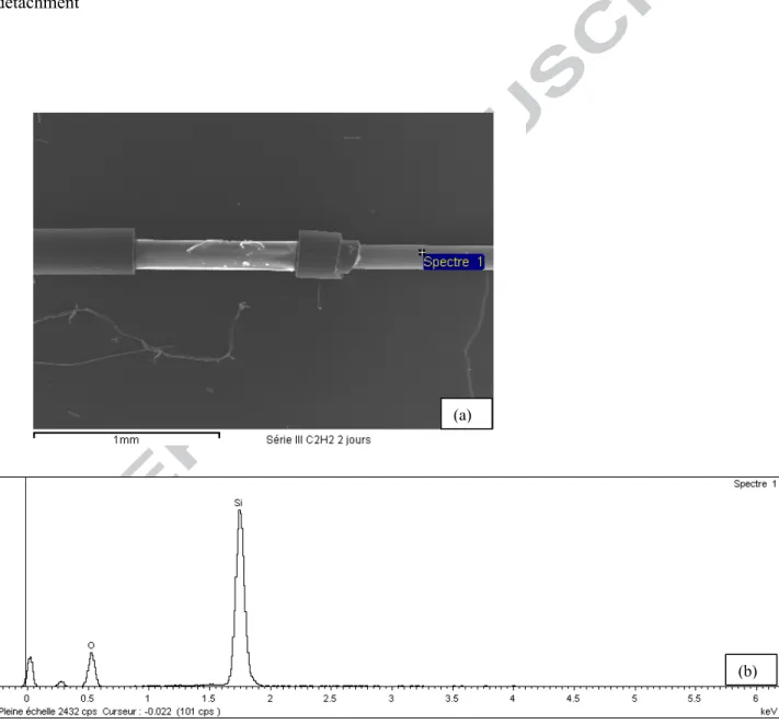
Exposure to ammonia reagent led to the strength decrease, the Weibull plot presenting a mono-modal distribution, similar to the reference (non-aged SOF). A similar distribution was registered following exposure to acetylene for the same duration (7 days), but the decrease was less severe. The most aggressive reagent was DMSO in liquid phase, an organo-sulphur compound and universal solvent capable to stabilize cell membranes under rapidly changing conditions. The broader scattering, attributed to multimodal distribution, and the significant loss in mechanical resistance were noticed for an exposure
of 18 hours. For short exposure duration (40 min), the effect was less obvious in terms of strength decrease and extrinsic flaws broadening, too.
In acetylene an interesting opposite effect was identified. For short exposure duration (48 hours), the acetylene affects progressively leading to the strength decrease and broader distribution. For long exposure duration (7 days), the strength decrease was less severe. This interesting behavior appears similar to the structural relaxation phenomenon, noticed in humid environment [16], so a similar hypothesis may be considered. It might be supposed that partial polymerization at the interface level is responsible for the less severe decrease of the mechanical strength and less broad distribution of extrinsic flaws.
Finally, relevant samples of etched fibres were investigated by scanning electron microscopy (SEM) and subjected to chemical analysis using a JEOL JSM-6301F scanning microscope. The polymer coating appears detached from the silica subsequent aging in DMSO (Fig. 12-a and 13-a) and acetylene (Fig. 14-a). The silica core appears peeled-off, while the two layer polymer coating may be seen from the diameter difference. Filaments of the soft inner layer (Fig. 12-a) exhibit the structure difference. The chemical analysis was performed pointing the layers similar to that presented in Figures 12 – 14 (b). As noticed in the chemical analysis, the silica cladding is indicated by Si and O peaks.
Considering these observations, in applications highly demanding chemical reliability, hermetical coated optical fibres might be advisable [21], realising a balance of cost and required performance.
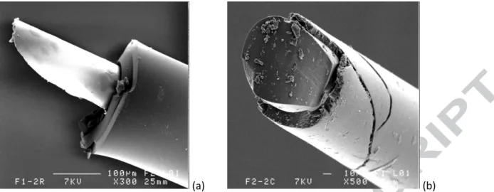
In particular structures, with SOF embedded in composite systems, detailed testing of SOF to components reactivity is needed. As previously presented [22] better coherence and adhesion at the OF/composite interface has been reported for the single polymer layer SOF 80/101.8. The polymer may be fractured (Fig. 15), but internal stresses seem more significant due to the polymerisation cycle of the composite resin in the case of the standard epoxy-acrylate SOF. The soft polymer layer appeared retracted or in other cases the silica cladding was stripped (Fig. 15-a); that’s why the single layer optical fibre (Fig. 15-b) appear more adapted in these applications.
Conclusion
Silica optical fibers extend their use for sensing and structures monitoring in real time. The selection is given by the balance between performance and cost. Based on previous experimental studies, polymeric coatings appear effective in reducing surface flaws at the silica cladding.
For tested fibre length and testing time economy reasons, dynamic testing appears more effective. The standard silica optical fiber with double epoxy-acrylate coating, tested in accordance with the International standard [15], has good mechanical strength ranging up to 7 GPa, as given by the Weibull
statistical analysis (Fig. 5). These optical fibers present aging sensitivity to chemical reagents due to polymer permeability and cladding-polymer interface reactivity.
In order to improve the fibre reliability, hydrogen diffusion through the silica cladding surface should be avoided. In-line deposition of a thin layer of diamond like carbon, followed by the subsequent polymer coating polymerisation, may improve the fabrication process. The hermetic coated fibres present lower mechanical strength ranging between 3.6 to 4.1 GPa (Fig. 5), but subjected to fluorinated vapours, known as critical for silica [7], the carbon protection appeared quite effective. Extensive exposure (12 days) of the hermetic coated fibres leads to a decrease of less than 10 % of the initial strength (Fig. 8).
Comparing other reactive reagents effect, such as organic compound (dimethyl-sulfoxide), acetylene and ammonia, the harshest action is attributed to the organic reagent DMSO (liquid reagent); in this case, the polymer coating detached rapidly through peeling-off after 40 min of soaking. SEM (a) and chemical analysis (b) confirmed the mechanical testing investigation (Fig. 12-14). The silica cladding is indicated by Si and O peaks, while the polymer coating layers (evidenced, but not included) are indicated by C (majority) and few O.
In ammonia exposure (vapour reagent), the polymer coating fractured, but in acetylene (vapour reagent) an opposite effect was noticed with less aggressive influence for longer exposure. The effect may be similar to the structural relaxation phenomenon evidenced in long term aging in humid environment [16]. Less severe decrease of the mechanical strength in certain conditions of exposure to acetylene may be explained by partial polymerization at the interface level that may be responsible for less broad distribution of extrinsic flaws.
In order to improve chemical reliability, the hermetic deposition may be applied, but the ends should be carefully protected, too. The relaxation phenomenon, with a benefit effect at interface level, may be initiated in certain conditions to be experimentally determined and controlled.
When embedding silica optical fibers in epoxy glass composite, the interface coherence at silica cladding / polymer coating appears critical. Previous testing [22] revealed that silica optical fibers with single layer polymer coating (80/101.8) exhibited better interfacial adhesion strength than classical double coating SOF. The inner soft polymer layer detached from the cladding, affecting the interface coherence.
For dedicated applications with embedded optical fibres, a controlled selection of the optical fibres geometry and manufacturing technology, linked to the cost, should be carefully considered. In this selection, the chemical reactivity to different components should be in advance investigated, as each factor (such as chemical reactivity, temperature, exposure time, applied stress) may influence differently with certain potential mutual compensation. Partial polymerization at interface level may be benefit, as identified in humid environment, too, but parameters to control the process should be again experimentally determined.
Acknowledgements
The authors express their gratitude to Verrillon, Inc. (North Grafton, MA), DFC-DCP (Creil, France), iXFiber S.A.S. (Lannion, France) for technical assistance and for material support. A special remark for M. Joseph le Lannic from C.M.E.B.A. for SEM observations and fruitful comments.
This research did not receive any specific grant from funding agencies in the public, commercial or non-for-profit sector.
References
[1] Davidson, R.; Roberts, S. Optical Fiber Sensor Compatibility and Integration in Composite Materials. In Comprehensive Composite Materials; Elsevier: Amsterdam, the Netherland, 2000; Volume 5, pp. 591–606.
[2] Luyckx G., Voet E., Lammens N., Degrieck J., Strain Measurements of Composite Laminates with Embedded Fibre Bragg Gratings: Criticism and Opportunities for Research, Sensors, MDPI, 2011, Vol. 11, pp. 384-408. [3] Zhou, G.; Sim, L.M. Evaluating damage in smart composite laminates using embedded EFPI strain sensors. Opt. Lasers Eng. 2009, 47, 1063–1068.
[4]. Bettini, P.; di Landro, L.; Airoldi, A.; Baldi, A.; Sala, G. Characterization of the interface between composites and embedded fiber optic sensors or NiTiNOL wires. Procedia Eng. 2011, 10, 3490–3496.
[5] Wang C. H., Soufiane A., Majid I., Wei R. Drenzek G., 17th International Conference on Optical Fibres Sensors. Proc. SPIE, Vol. 5855, pp. 563- 568, 2005.
[6]. Kukureka S. N., Miao P., Metje N. , Chapman D. N., Rogers C. D.F, Henderson P. R., 17th International Conference on Optical Fibres Sensors, Proc. SPIE, Vol. 5855, pp. 1052-1057, 2005
[7] Mathewson, M.J., Kurkjian, C.R., Hamblin, J.R., J. Lightwave Technol. 15 (3) pp. 490-496, 1997
[8] Wade, S.A., Wallbrink, C.D., McAdam, G a.o, A fibre optic corrosion fuse sensor using stressed metal-coated fibres, Sensors and Actuators B 131, pp. 602-608, 2008
[9] Benounis, M., Jaffrezic-Renault, N., Elaboration of an optical fibre corrosion sensor for aircraft applications, Sensors and Actuators B 100, pp. 1-8, 2004
[10] Aleixandre, M., Corredera, P., Hernanz, M.L., Gutierrez-Montreal, J., Development of fibre optic hydrogen sensors for testing nuclear waste repositories, Sensors and Actuators B 107, pp. 113-120, 2005
[11] Elosua, C., Bariain, C., Matias, I., Arregui F. a.o Optical fiber sensing devices based on organic vapor indicators towards sensor array implementation, Sensors and Actuators B 137, pp. 139-146, 2009
[12] Austin, E. van Brakel, A, Petrovich, M., Richardson, D. Fibre optical sensors for C2H2 gas using-filled photonic bandgap fibre reference cell, Sensors and Actuators B 139, pp. 30-34, 2009
[13] Ding, H., Liang, J., Cui, J., Wu, X., A novel fiber Fabry-Perot filter based mixed-gas system, Sensors and Actuators B 138, pp. 154-159, 2009
[14] Fleetwood, D.M., Rodgers, M. P., Tsetseris, L., Zhou, X.J., a.o, Microelectronics reliability 47, pp. 1075-1085, 2007
[16] ElAbdi R., Dumitrache - Rujinski A., Poulain M., Severin I., Damage of Optical Fibres under Wet Environments, Experimental Mechanics, 50, pp. 1225–1234, 2010
[17] Kukureka S. N., Cairns D. R., Statistical analysis for strength distribution in optical fibres, Proc. SPIE Conf. on Optical Fibre Reliability and Testing, Vol. 3848, Boston, pp. 17-27, 1999.
[18] Griffioen W., Optical Fibre Reliability, Thesis edited by Royal PTT, The Netherlands NV, PTT Research, Leidschendam, 1994.
[19]. Weibull W., The Phenomenon of Rupture in Solids, Vol.153, pp.1-55, Igeniors Vetenskaps, Akademiens, Handlingar, 1939.
[20]. Weibull W., J. Appl. Mech., 18, pp. 293-298, 1951.
[21]. Shiue S.T, Hsiao H.H., Shen T.Y., Lin H.C., Lin K.M., Mechanical strength and thermally induced stress voids of carbon-coated optical fibres prepared by plasma enhanced chemical vapour deposition method with different hydrogen/methane ratio, Thin Solid Films 483, pp. 140-146, 2005
[22]. Severin I., ElAbdi R., Corvec G., Caramihai M., Optical Fiber Embedded in Epoxy Glass Unidirectional Fiber Composite System, Materials, MDPI, Vol. 7, pp. 44-57, 2014
10
Figure 1. SEM of 125/250 silica optical fibre (cladding 125 μm, two layer epoxy-acrylate coating 250 μm)
Figure 2. SEM of 80/101.8 silica optical fibre (cladding 80 μm, single layer coating 101.8 μm)
Figure 3. Two point bend test setup
Fiber Faceplates Control Block Piezoelectric Sensor Stepper motor Computer
A
FiberFi ber FaceplatesFa ceplates Control BlockCo Piezoelectric SensorPiezoelec tricSensor motorSteStepper pper motor ComputerCom puter
A
A
Fiber sample Faceplate sample Faceplate Detail A Fiber Faceplates Control Block Piezoelectric Sensor Stepper motor ComputerA
Fiber Faceplates Control Block Piezoelectric Sensor Stepper motor ComputerA
Fiber sample Faceplate sample Faceplate Detail A Fiber Faceplates Control Block Piezoelectric Sensor Stepper motor ComputerA
cladding coatingFigure 4. Dynamic tensile test setup
8 8.2 8.4 8.6 8.8 9 -4 -4 -2 -2 00 v=100 μm/s v=200 μm/s v=400 μm/s v=800 μm/s H v=100 μm/s H v=200 μm/s H v=400 μm/s H v=800 μm/s
Verrillon Fiber : standard SOF as compared to hermetically coated
ln (stress, MPa)
ln(-1/L*ln(1-Fk))
Figure 5. The effect of the hermetical (H) in-line deposition on the mechanical strength of as-received SOF for different strain rates (in μm/s)
7.4 7.9 8.4 -4 -4 -2 -2 00 reference 20 h-f 20 h-c 27 h-f 27 h-c 48 h-f 48 h-c 68 h-f 68 h-c 96 h-f 96 h-c 120 h-f 120 h-c 144 h-f 144 h-c 164 h-f 164 h-c Verrillon SOF: as aged at 55°C (strain rate 200 μm/s)
ln (stress, MPa)
ln(-1/L*ln(1-Fk))
Figure 6. Fibre strength decrease following exposure to fluorinated reagents (in legend the aging duration, in hours; f far from vapours release, c close to vapours release)
0 2 4 6 8 10 12 14 16 3250 3300 3350 3400 3450 3500 3550 3600 3650 3700 3750
Med Stress far Med Stress close
Verrillon hermetically coated SOF: as-aged
Aging duration, days
Stress, GPa
Figure 8. Influence of hermetical protection of silica cladding in aging conditions in fluorinated environment at 55°C 8 8.05 8.1 8.15 8.2 8.25 8.3 8.35 -4 -2.5 -1 0.5 v=100 μm/s far v=100 μm/s close v=200 μm/s far v=200 μm/s close v=400 μm/s far v=400 μm/s close v=800 μm/s far v=800 μm/s close v=200 μm/s reference
Verrillon hermetically coated SOF: aged 14 days
ln (stress, MPa)
ln(-1/L*ln(1-Fk))
Figure 10. Harsh etching of unprotected end of silica cladding in fluorinated environment (H SOF)
7.5 7.6 7.7 7.8 7.9 8 8.1 8.2 8.3 8.4 8.5 8.6 -4.5 -3 -1.5 0 1.5 reference 200 mm/min acetylene 7 days acetylene 48h DMSO 18h ammonia 7 days Verrillon fibre / NH3, C2H2, C2H2SO ln (stress, MPa) ln(-1/L*ln(1-Fk))
Figure 12. SEM (a) and chemical analysis (b) of DMSO aged SOF for 40 minutes: polymer coating peeling-off
(a)
(b)
Figure 13. SEM (a) and chemical analysis (b) of DMSO aged SOF for 18 hours: polymer coating detachment
Figure 14. SEM (a) and chemical analysis (b) of SOF aged in acetylene for 48 hours: polymer coating peeling-off
(a)
(b) (b)
(a) (b)
Figure 15. Optical fibre embedded in epoxy glass unidirectional composite system: polymer damage (a – double polymer coating; b- single polymer coating)