OIF-SMI-01.0
September 4, 2003
Implementation Agreement Created and Approved by the Optical Internetworking Forum
www.oiforum.com
Security for Management Interfaces to
Network Elements
Working Group: OAM&P
TITLE: Security for Management Interfaces to Network Elements
DATE: September 4, 2003
SOURCE: Renée Esposito, Booz Allen Hamilton, [email protected] Richard Graveman, Department of Defense, [email protected]
Brian Hazzard, PhotonEx, [email protected]
Document Status: Approved IA
Project Name: Security for Management Interfaces to Network Elements and Auditing & Logging for Network Elements
Project Number: oif2002.346.06
ABSTRACT: This Implementation Agreement lists objectives for securing OAM&P interfaces to a Network Element and then specifies ways of using security systems (e.g., IPsec or TLS) for securing these interfaces. It summarizes how well each of the systems, used as specified, satisfies the objectives.
Notice: This implementation agreement document has been created by the Optical Internetworking Forum (OIF). This document is offered to the OIF Membership solely as a basis for agreement and is not a binding proposal on the companies listed as resources above. The OIF reserves the rights to at any time to add, amend, or withdraw statements contained herein. Nothing in this document is in any way binding on the OIF or any of its members.
The user’s attention is called to the possibility that implementation of the OIF implementation agreement contained herein may require the use of inventions covered by the patent rights held by third parties. By publication of this OIF implementation agreement, the OIF makes no representation or warranty whatsoever, whether expressed or implied, that implementation of the specification will not infringe any third party rights, nor does the OIF make any representation or warranty whatsoever, whether expressed or implied, with respect to any claim that has been or may be asserted by any third party, the validity of any patent rights related to any such claim, or the extent to which a license to use any such rights may or may not be available or the terms hereof.
For additional information contact:
The Optical Internetworking Forum, 39355 California Street, Suite 307, Fremont, CA 94538 510-608-5928 phone Φ [email protected]
Copyright (C) The Optical Internetworking Forum (OIF) (2001). All Rights Reserved.
This document and translations of it may be copied and furnished to others, and derivative works that comment on or otherwise explain it or assist in its implementation may be prepared, copied, published and distributed, in whole or in part, without restriction other than the following, (1) the above copyright notice and this paragraph must be included on all such copies and derivative works, and (2) this document itself may not be modified in any way, such as by removing the copyright notice or references to the OIF, except as needed for the purpose of developing OIF Implementation Agreements.
By downloading, copying, or using this document in any manner, the user consents to the terms and conditions of this notice. Unless the terms and conditions of this notice are breached by the user, the
limited permissions granted above are perpetual and will not be revoked by the OIF or its successors or assigns.
This document and the information contained herein is provided on an “AS IS” basis and THE OIF DISCLAIMS ALL WARRANTIES, EXPRESS OR IMPLIED, INCLUDING BUT NOT LIMITED TO ANY WARRANTY THAT THE USE OF THE INFORMATION HEREIN WILL NOT INFRINGE ANY RIGHTS OR ANY IMPLIED WARRANTIES OF MERCHANTABILITY, TITLE OR FITNESS FOR A PARTICULAR PURPOSE.
List of Contributors
Gary Buda, Booz Allen Hamilton [email protected]
Renée Esposito, Booz Allen Hamilton [email protected]
Richard Graveman, Telcordia and Department of Defense [email protected]
Brian Hazzard, PhotonEx [email protected]
Scott McNown, Department of Defense [email protected]
John Naegle, Department of Defense [email protected]
Dimitrios Pendarakis, Tellium [email protected]
Tom Tarman, Sandia National Labs [email protected]
TABLE OF CONTENTS 1 DOCUMENT SUMMARY ... 1 1.1 WORKING GROUP... 1 1.2 PROBLEM STATEMENT... 1 1.3 SCOPE... 2 1.4 EXPECTED OUTCOME... 3 1.5 VALUE TO OIF... 4
1.6 RELATIONSHIP TO OTHER STANDARDS BODIES... 4
1.7 VIEWPOINT... 4
1.8 ACKNOWLEDGEMENT... 4
2 INTRODUCTION ... 5
2.1 OUTLINE OF THE IMPLEMENTATION AGREEMENT... 5
2.2 HOW TO USE THIS IMPLEMENTATION AGREEMENT... 5
2.3 DOCUMENT ORGANIZATION... 5
2.4 KEYWORDS... 6
3 TERMINOLOGY AND ACRONYMS ... 6
3.1 TERMINOLOGY... 6
3.2 ACRONYMS... 7
4 THREATS AND SECURITY OBJECTIVES... 8
4.1 CONFIDENTIALITY... 9
4.2 DATA INTEGRITY... 9
4.3 KEY MANAGEMENT... 10
4.4 AUTHENTICATION... 10
4.5 NEGOTIATION AND POLICY ENFORCEMENT... 11
4.6 NON-REPUDIATION... 11
4.7 ACCESS CONTROL... 11
4.8 AUDIT AND EVENT LOGGING... 12
4.9 DENIAL OF SERVICE... 12
4.10 TRAFFIC ANALYSIS... 12
5 MANAGEMENT INTERFACES AND PROTOCOL STACKS ... 13
5.1 PROTOCOL STACKS AND SECURITY... 13
5.2 PROTOCOL STACKS AND VPNS... 14
5.3 MANAGEMENT INTERFACES AND SECURITY PROTOCOLS... 15
6 SECURITY SYSTEMS AND SPECIFICATIONS ... 16
6.1 IPSEC... 16
6.1.1 IPsec Description ... 16
6.1.2 Specifications for Using IPsec... 18
6.2 SSL AND TLS ... 20
6.2.1 SSL and TLS Description... 20
6.2.2 Specifications for Using SSL and TLS ... 20
6.3 SNMPV3 ... 22
6.3.1 SNMPv3 over Different Transport Layers... 22
6.3.2 SNMPv3 Description ... 22
6.3.3 Specifications for Using MIB-Based Management–SNMPv3... 23
6.4 SECURE SHELL (SSH) ... 24
6.4.1 SSH Description ... 24
6.5 KERBEROS... 26
6.5.1 Description of Kerberos ... 26
6.5.2 Specifications for Using Kerberos... 26
6.6 OTHER PROTOCOLS SUPPORTING SECURITY... 27
6.6.1 RADIUS ... 27
6.6.2 S/MIME... 28
7.0 OBJECTIVES SATISFIED BY SECURITY SYSTEMS ... 28
8.0 REFERENCES ... 30
8.1 NORMATIVE REFERENCES... 30
8.2 INFORMATIVE REFERENCES... 32
LIST OF TABLES TABLE 1:APPLICABILITY OF SECURITY SOLUTIONS TO DIFFERENT INTERFACES………...16
TABLE 2:REQUIREMENTS CONFORMANCE MAPPING………..…..28-29 LIST OF FIGURES FIGURE 1:NETWORK MANAGEMENT SECURITY REFERENCE MODEL………...3
FIGURE 2:TYPICAL PROTOCOL STACKS FOR MANAGEMENT INTERFACES………..13
FIGURE 3:PROTOCOL STACKS INCLUDING SECURITY……….14
FIGURE 4:PROTOCOLS STACKS INCLUDING A VPN………...………..15
FIGURE 5A:AH IN TRANSPORT MODE………..………..………17
FIGURE 5B:ESP IN TRANSPORT MODE…………...……….………17
FIGURE 6A:AH IN TUNNEL MODE………..17
Security for Management Interfaces to Network
Elements
1
Document Summary
This Implementation Agreement (IA) consists of two main parts. The first (Section 4) lists objectives for securing the protocols used over OAM&P interfaces to a Network Element (NE). The second (Sections 5–7) presents a model for securing these protocols at different layers, describes systems that are well-suited to secure these interfaces at
various protocol layers, gives specifications for using these security systems
appropriately, and summarizes how such security systems achieve the objectives in the first part. The term objectives is used in Section 4 because not all of these items are
requirements for all users. Users are advised to decide which objectives are requirements
for them and choose a solution specified in Section 6 that best meets the objectives they consider requirements. Each security system provides multiple security services, e.g., authentication, integrity, and confidentiality. A major goal of this IA is to define interoperable and high-quality security solutions for these OAM&P interfaces. This is accomplished by specifying how to use these security systems simply and effectively to achieve as many of the listed security objectives as possible.
1.1 Working
Group
OAM&P Working Group.1.2 Problem
Statement
The OIF has addressed security in its UNI and NNI specifications, which describe how NEs use various control protocols for signaling, routing, and discovery. NEs, however, typically have one or more (in some cases many) OAM&P interfaces used for network management, billing and accounting, configuration, maintenance, and other
administrative activities. Remote access to a NE through these OAM&P interfaces is frequently a requirement. Securing the control protocols while leaving these OAM&P interfaces unprotected opens up a huge security vulnerability. NEs are an attractive target for hackers who want to disrupt or gain free access to telecommunications facilities, and much has been written about this subject since the 1980s. A magazine, 2600, is devoted to such activities. At one time, careful access controls and password management were a sufficient defense, but no longer. Networks using the TCP/IP protocol suite are
vulnerable to, among other things, forged source addresses, recording and later replay, packet sniffers picking up passwords, re-routing of traffic to facilitate eavesdropping or tampering, active hijacking attacks on TCP connections, and a variety of denial of service attacks. In the 1990s, telecommunications facilities were identified in the U.S. as part of the “critical infrastructure,” and increased emphasis was placed on thwarting such attacks from a wider range of potentially well-funded and determined adversaries. The ease of forging TCP/IP packets is the main reason network management protocols lacking strong security have not been used to configure NEs (e.g., with the SNMP SET command). Readily available hacking tools exist that let an eavesdropper on a LAN take over one
end of any TCP connection, so that the legitimate party is cut off. In addition, some Enterprises and Carriers in some jurisdictions need to safeguard data about their users and network configurations from prying. An attacker could eavesdrop and observe traffic to analyze traffic usage patterns and map a network configuration; an attacker could also gain access to systems and manipulate configuration data or send malicious commands. Therefore, in addition to authenticating the human user (see [T1M1]), more sophisticated protocol security is needed for OAM&P interfaces, especially when they are configured over TCP/IP stacks. Finally, relying on a perimeter defense, such as firewalls, is
insufficient protection against “insider attacks,” or penetrations that compromise a system inside the firewall as a launching pad to attack NEs.
1.3 Scope
The scope of this IA is to define security objectives for OAM&P access to NEs and to specify how to use different security systems, depending on the OAM&P protocol and security requirements, to achieve these objectives.
The emphasis in this IA is on protocol security between a Management System and NE. This IA does not differentiate strongly among security attributes associated with a human user, process, application, and system. In many cases, there may be no direct human user involved an operation, and many NEs and OAM&P systems do not distinguish different “user-IDs” or applications. However, in addition to using the protocol security methods in this IA, additional methods may be used to enforce access controls based on such distinctions.
System security of the NEs, Network Management Systems (NMS), and Element Management Systems (EMS) are out of scope, although some remarks in this IA may address the need to safeguard the cryptographic protocol protections themselves. System security for network elements is addressed elsewhere. For more on information
assurance requirements, system security requirements, and security-related functional requirements to which products can be developed please refer to [Tel1], [Tel2], and [IATF].
The threats identified in the Problem Statement emphasize the vulnerabilities of running OAM&P interfaces over TCP/IP protocol stacks, so this IA addresses protocol security for TCP/IP-based OAM&P interfaces. Other types of OAM&P interfaces exist, from sophisticated ones such as the data communications channels over SONET described in [ANSI95] to a simple hard-wired RS-232 connection. In addition, [ITUDCN] describes hybrid networks that use IPv4 as well as other network layer protocols over a variety of layer 2 infrastructures. It also describes encapsulation or tunneling methods. Some of the methods in this IA can possibly be applied to such configurations. For example, protocols tunneled over IPv4 can be protected with IPsec. However, protocols other than those running over TCP/IP stacks are, in general, out of scope for this document.
The rationale for this IA is that NEs using the OIF’s Security Extension for UNI and NNI
[Gra03] have strong security for their optical signaling protocols, but security on these NEs may be weakened or compromised by not having comparable protection for their OAM&P interfaces. Therefore, the immediate scope of this IA is NEs that run the OIF’s UNI or NNI signaling protocols. However, most, perhaps all, of the material in this IA is not particular to optical network elements but is applicable to any network element (NE)
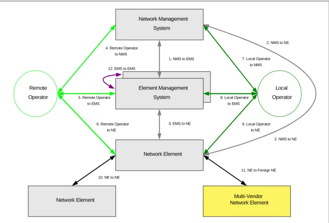
and its Management Systems. This interface is shown as number 3 in Figure 1 (or as number 1 for the case in which the EMS and NE are packaged as a single entity). (Figure 1 is taken from [T1M1].) In fact, many NEs switch or route traffic over other types of networks besides optical. These NEs are usually managed by a single set of OAM&P protocols running over a set of OAM&P interfaces. In these cases, the security measures described in this IA may be applied to all such OAM&P interfaces.
NEs, in the larger sense, may be “distributed systems” that are divided, for example, into control and transport components or that have proxy components to carry out certain functions. Multiple components may also exist for redundancy or load balancing. Each such component that has its own OAM&P interface(s) is regarded as a NE in this IA. Section 3.2 of [Gra03] describes different Service Invocation Configurations and Signaling Transport Configurations. Again, the primary intention is to protect NEs running the OIF’s signaling protocols, but wider applicability is not precluded. For descriptions of such configurations, see also [ANSI95] and [ITUDCN].
Network Management System Network Element Remote Operator Local Operator
Network Element Network ElementMulti-Vendor
2. NMS to NE 1. NMS to EMS 3. EMS to NE 4. Remote Operator to NMS 5. Remote Operator to EMS 6. Remote Operator to NE 7. Local Operator to NMS 9. Local Operator to NE 8. Local Operator to EMS 10. NE to NE 11. NE to Foreign NE 2. NMS to NE Element Management System Element Management System 12. EMS to EMS
Figure 1. Network Management Security Reference Model (T1M1).
1.4 Expected
Outcome
The goal of this work is to complement the efforts to secure the control protocols in the UNI and NNI with a corresponding level of security for OAM&P protocols to achieve appropriate levels of interoperable security in both the control and management planes.
1.5 Value to OIF
This IA helps vendors (of both NEs and Management Systems), service providers, and enterprises achieve a uniform level of security across all of the protocols used for OAM&P access to NEs. Achieving a uniform level of security is important, because experience has shown that attacks are usually directed at the weakest point.
1.6 Relationship to Other Standards Bodies
• The ATM Forum has published a specification on securely managing ATM network elements [ATMF02]. This IA is patterned after the ATM Forum’s document; certain aspects of the two documents are quite similar, other aspects are substantially
different.
• This IA uses the RFCs written by the IETF as normative references to almost all of the security systems described herein: Kerberos, SSH, TLS, SNMPv3, IPsec, Radius, and S/MIME. The only exception is SSL.
• T1M1 has written security requirements for the management plane [T1M1]. That document addresses security of the management plane for the public switched network, and this document is aligned with the terminology and reference diagram used by T1M1. Note that [T1M1] places requirements on NEs for security, defines administrative roles, places requirements on end systems, and also addresses physical security; this document does not. This document, written to be consistent with the requirements specified in [T1M1], provides narrow guidance for selecting,
implementing, and deploying protocol security systems to protect TCP/IP-based management interfaces to NEs.
1.7 Viewpoint
This document defines no new protocols. It consolidates, profiles, and applies many aspects of work done at other standards bodies, particularly the IETF.
1.8 Acknowledgements
Much of the text in Sections 3–7 of this document was adapted from the ATM Forum’s
Methods for Securely Managing ATM Network Elements— Implementation Agreement
[ATMF02]. The OIF acknowledges this helpful starting point.
This document has been written in cooperation with T1M1.5, and multiple rounds of drafts and comments on each other’s drafts were exchanged between the OIF and T1M1.5. All of the comments were accepted in good faith and integrated, as far as
possible, by both organizations. The terminology and reference model from [T1M1] have been adopted herein, as well as the administrative roles specified in [T1M1], which are covered in Section 4.7, Access Control. Additional references to [T1M1] are included in appropriate places.
2 Introduction
The goal of this IA is to specify how to apply security to management interfaces to NEs by using:
• High-quality, standard systems of security protocols, which provide a full range of security services and mechanisms and have multiple interoperating implementations, • Integrated and automated key management, and
• Consistent identification, authentication, and authorization of network administrators (NAs). Note that [T1M1] identifies different types of administrators with different roles. In this document, the term “NA” applies to any and all of these.
Management interfaces include all access methods and protocols used for network or element management, administration, operations, maintenance, and related tasks.
2.1 Outline of the Implementation Agreement
This IA begins by enumerating objectives, listed in Section 4, for securing management interfaces to a NE. The three sections after that focus on how to apply existing security systems (e.g., Kerberos, TLS, SSH, SNMPv3, or IPsec) to provide secure management access to a NE. Section 5 describes the different types of management interfaces, the protocol stacks they may use, and where the different security systems fit into a typical TCP/IP protocol stack. To promote interoperability, it recommends a preferred solution. Section 6 briefly describes the different security systems, provides references to them, and states specifications for using them appropriately. Section 7 shows the extent to which the proper use of these security systems satisfies the objectives in Section 4. This IA does not define any new protocols or management information.
2.2 How to Use this Implementation Agreement
Vendors of NEs or Management Systems should determine which protocol stacks their OAM&P interfaces use and refer to the appropriate sections for guidance on which security alternatives they have and which options to prefer in each of these cases.
Service Providers and enterprises should first examine the security objectives in Section 4 to determine which security objectives are critical requirements for their operations. Then, they should use this document to map their requirements to the most appropriate security solutions.
2.3 Document
Organization
This document is organized as follows:{ Section 3 defines the terminology and acronyms used.
{ Section 4 lists and describes the security objectives.
{ Section 5 describes the typical protocol stacks used by management interfaces and where security systems fit into these stacks. Among these, it recommends one choice.
{ Section 6.1 covers securing protocols that run over IP with IPsec.
{ Section 6.3 covers securing MIB-based management systems with SNMPv3.
{ Section 6.4 covers securing command line protocols with SSH.
{ Section 6.5 covers securing application layer protocols with Kerberos.
{ Section 6.6 covers use of these solutions together with Radius or S/MIME.
{ Section 7 maps the security systems in Section 6 to the objectives in Section 4.
{ Section 8 contains normative and informative references.
Each subsection of Section 6 presents a general description and specifications for using one security system aimed at satisfying the security objectives in Section 4. The table in Section 7 summarizes which security objectives from Section 4 are fulfilled by following the specifications in Section 6. The specifications for using each of the security systems in Section 6 are aimed:
1. To promote conformance of systems secured by the given security system with the security objectives in Section 4,
2. To promote interoperability of such implementations with commonly available and current implementations, and
3. To help configure these systems according to generally accepted best practices.
2.4 Keywords
When written in ALL CAPITALS, the key words “MUST”, “MUST NOT,” “REQUIRED,” “SHALL,” “SHALL NOT,” “SHOULD,” “SHOULD NOT,”
“RECOMMENDED,” “MAY,” and “OPTIONAL” in the specifications in Sections 5 and 6 of this document are to be interpreted as described in IETF RFC 2119 [Bra97].
3 Terminology
and
Acronyms
3.1 Terminology
In this implementation agreement, the following definitions apply:
Network Element (NE): Any device implementing one or more of the OIF’s UNI or NNI control protocols. It may also support other interfaces or services. In this IA, a networking component with its own OAM&P interfaces (e.g., a signaling control or transport component), is considered a NE.
Element Management System (EMS): A terminal, network element, or system that provides specific services to manage specific Network Elements.
Network Management System (NMS): A terminal, network element, or system that provides services to manage a Network Element. It may be an overall management system that manages multiple EMSs and Network Elements, including non-optical Network Elements.
Management System: A generic term for an EMS or NMS.
Network Administrator (NA): A person who is authorized to use a Management System. (Refer to [T1M1] for the many roles that may exist for a NA.)
3.2 Acronyms
The following acronyms or abbreviations are used in this implementation agreement:
AES Advanced Encryption Standard
CA Certification Authority
CBC Cipher Block Chaining
CMIP Common Management Information Protocol
CORBA Common Object Request Broker Architecture
CRC Cyclic Redundancy Check
DES Data Encryption Standard
DH Diffie-Hellman
DSS Digital Signature Standard
EMS Element Management System
ESP Encapsulating Security Payload
ICMP Internet Control Message Protocol
IKE Internet Key Exchange
IP Internet Protocol
IPsec IP Security
KDC Key Distribution Center
MAC Message Authentication Code
MIB Management Information Base
NA Network Administrator
NE Network Element
NMS Network Management System
RSA Rivest, Shamir, and Adleman
RFC Request for Comments
SA Security Association
SAD Security Association Database
SHA Secure Hash Algorithm
S/MIME Secure Multipurpose Internet Mail Extensions
SNMP Simple Network Management Protocol
SPD Security Policy Database
SSH Secure Shell
SSL Secure Sockets Layer
TCP Transmission Control Protocol
TGT Ticket Granting Ticket
TL1 Transaction Language 1
TLS Transport Layer Security
4 Threats and Security Objectives
The general threat model is that anyone can read or write arbitrary information on the same network as the legitimate parties. In fact, attacks can be combined: information can be read and modified or deleted, or recorded and played back later in an identical or modified form. Source and destination addresses and other control information (e.g., a TCP reset) and control protocols (e.g., ICMP) can also be forged or manipulated. Anyone can gain full knowledge of the legitimate protocols, including security protocols, being used. However, we assume that no one can completely stop the flow of legitimate packets. Also, the legitimate parties can be initially configured with cryptographic mechanisms and secrets, they can secure their internal state (memory) from reading or tampering, and they can generate cryptographically sound pseudorandom numbers. Providing security to protect against this threat model includes defenses against attacks often labeled as:
• Masquerade. Attacks under this heading are often called spoofing, session hijacking, or man-in-the-middle. Masquerade usually implies impersonating the name or address of a legitimate party to gain access, carry out a malicious act, or observe the activities of a system and gain more knowledge about the system’s users or configuration. • Unauthorized access. Attacks under this heading include exploiting system
vulnerabilities to gain access and control of system resources, compromise a network node, cause incorrect operations, modify configuration data or software, or disable security features.
• Data integrity threats. This includes modifying, reordering, truncating, or replaying legitimate communications, or outright forgery.
• Confidentiality threats. Attacks under this heading include eavesdropping or “packet sniffing,” session recording, and disclosure. These attacks may occur when an attacker taps into a transmission facility or network node or otherwise captures data being transferred on a communications channel. An attacker may attempt cryptanalysis on captured and encrypted data to recover message properties or contents.
• Traffic analysis. This threat consists of an attacker being able to discern the configuration or usage patterns on a network, including the numbers and types of systems; names of parties; patterns, frequency, and volume of information communicated between them; and the protocol stacks they are using.
• Denial of Service (DoS). DoS occurs when an attacker executes commands or performs operations that cause undue burden on the network nodes and end systems, which results in resources being unavailable for authorized uses.
Vendors should address the above threats when incorporating security into their products or developing specific security products for their management, administration,
operations, and maintenance interfaces between their NEs and Management Systems. For the purposes of this document, “interfaces between NEs and Management Systems” is interpreted broadly to include all OAM&P communications with the NE, regardless of the Management System endpoint. Vendors should consider the following list of security
objectives and state which are met by their products. The term objectives is used in this Section, because not all of these items are requirements for all users. Users are advised to decide which objectives are requirements for them and to choose a solution specified in Section 6 that best meets the objectives they consider requirements.
4.1 Confidentiality
Confidentiality is used to protect data against partial or complete disclosure to unauthorized parties. Information that may need to be protected for confidentiality includes, but is not limited to, statistical data, configuration information, connectivity information, and management data transferred between a NE and a Management System. Cryptography or an interface to a cryptographic device will aid in retaining information confidentiality. It must be noted that data confidentiality relies upon entity authentication and data integrity. Users may consider the following objectives for ensuring
confidentiality:
C-1 The interface between the NE and the Management System supports confidentiality of management data transferred between the NE and the Management System.
C-2 The interface between the NE and the Management System supports confidentiality of passwords and keying material.
C-3 The interface between the NE and the Management System supports confidentiality of audit information.
C-4 The interface between the NE and the Management System provides confidentiality of identities and addressing information.
4.2 Data
Integrity
Data integrity is the ability to ensure that data have not been altered or destroyed in an unauthorized manner. For example, SNMP messages may have to be protected from being maliciously altered in such a way that the altered message could result in
unauthorized management operations, including falsifying the value of an object. Data integrity also ensures that the data sequence has not been altered in a manner that would cause unauthorized management operations. This extends to preventing replay attacks by ensuring that a message is not accepted multiple times or after undue delay. Note that data integrity cannot be obtained without data origin authentication. Users may consider the following objectives for ensuring data integrity:
I-1 The interface between the NE and the Management System supports message integrity for communications between the NE and the Management System. I-2 The interface between the NE and the Management System supports a mechanism
for replay protection for communications between the NE and the Management System.
I-3 The interface between the NE and the Management System supports integrity of audit information.
I-4 The interface between the NE and the Management System supports a mechanism to detect delay of communications between the NE and the Management System and prohibits communications that exceed the limits of a time window.
4.3 Key Management
Key management is the supervision and control of the process whereby keys are
generated, stored, protected, transferred, loaded, used, and destroyed. Users may consider the following objectives for key management:
K-1 Based on a secure system of installing pre-shared secrets or public-private key pairs, the interface between the NE and the Management System supports a dynamic key management system for the automated and secure establishment and distribution of key encryption keys (e.g., pre-shared secrets or master keys) that are shared between the Management System and the NE.
K-2 The interface between the NE and the Management System supports a key management system for the dynamic, automated, and secure establishment and distribution of traffic protection keys (i.e., the keys used to encipher and decipher or to generate and verify integrity checks of the actual OAM&P traffic) that are shared between the Management System and the NE.
K-3 The interface between the NE and the Management System provides forward secrecy for all confidential communications between the NE and the Management System. Forward secrecy means that subsequent compromise of long-term keys does not also compromise the contents of previous sessions that were set up using these long-term keys. It can be achieved, for example, by using long-term keys only to authenticate, but not to generate or encrypt, traffic protection keys.
K-4 The interface between the NE and the Management System provides a method for secure rekeying of traffic protection keys. The security of the rekeying is based on the authenticated and shared key encryption keys (K-1).
4.4 Authentication
Authentication protects communicating systems from accepting fraudulent data or revealing data to unauthorized parties by allowing them to verify the identity of the originator or recipient of a message, respectively. (For example, a goal of authentication may be to verify the identity of the user who claims to have generated a SNMP message.) As described in Section 1.3 on Scope, authentication is called for at the level of a system, but finer grained methods are allowed (e.g., user, process, or application level
authentication). Users may consider the following objectives for authentication: A-1 The interface between the NE and the Management System supports the
capability for each entity to establish and verify the claimed identity of the other. A-2 The interface between the NE and the Management System authenticates all
4.5 Negotiation and Policy Enforcement
When each OAM&P interface is originally configured, the security policy for using this interface may be specified. In general, stronger security is achieved if NEs and
Management Systems are delivered from the vendor with security options enabled and with appropriate warnings about disabling these options. Policy may be enforced by determining the security parameters for a communication session at session
establishment. Users may consider the following objectives for negotiation and policy enforcement:
N-1 The NE is configured to allow specification of the security systems, services, and options it requires for each OAM&P interface.
N-2 The interface between the NE and the Management System supports secure negotiation of the security services, mechanisms, and algorithms used to protect OAM&P protocols. This may be achieved, for example, if the first party can list acceptable choices for these parameters and the second party can select from these choices which to use.
4.6 Non-Repudiation
Non-repudiation of message origin is the ability to guarantee to a third party the
originator’s authenticity and the integrity of a message, so that the originator cannot deny having sent the message. Users may consider the following objective for
non-repudiation:
R-1 The interface between the NE and the Management System provides a protocol that supports non-repudiation of message origin.
4.7 Access
Control
Access control defines and restricts the privilege to access information or perform specific functions to certain entities, roles, or systems. Entities are referenced by user IDs
or login names that identify users to different operating systems. Roles are defined by
groups or privileges granted to entities, again, depending upon the operating system. In
some environments, the role of Network System Administrator is distinct from the role of
System Security Administrator, whereas in other environments a single privileged role is
defined. See, for example, [T1M1] for the definition of five types of administrative roles: Application Administrator, Application Security Administrator, System Administrator, System Security Administrator, and Application User/Operator. The term Network Administrator (NA) is used when referring to all types of administrators. However, it is important to remember that each administrative role may have specific functions and privileges. For instance, a System Security Administrator may be responsible for the proper activation, maintenance, and use of the security features of a system (i.e., NE or Management System). On the other hand, a System Administrator may be responsible for OS-level processes and procedures pertaining to installation, operations, and maintenance of the operating platform; installation of software on the platform; and control of
privileged authority. For the most part, the security systems described in Section 6 can function with entities defined at the level of an entire system, but most of them may also
be used with finer-grained access controls. Thus, users may consider the following objectives for access control:
AC-1 The NE provides the means to limit the actions of a NA based upon the NA’s identity or role.
AC-2 The NE provides the means to limit a NA’s privileges based on criteria such as the OAM&P port, protocol, time of day, or specific command.
4.8 Audit and Event Logging
Auditing and logging network events provides a chronological record of system activities and allows the examination of sequences of events or changes in state. The information audited and captured in a audit log may be configurable and needs to be protected from unauthorized access, tampering, or removal. Users may consider the following security objectives for auditing and logging network events:
L-1 The NE is capable of recording a set of events that is specified by a NA, according to the access controls granted to the NA.
L-2 The NE is capable of reporting events selected by a NA to the Management System as they occur in real time.
L-3 The NE is capable of recording the system time to a granularity of no greater than one second at which each audited event occurred.
L-4 The NE is capable of recording the identity of the NA who performed each action. L-5 The NE is capable of presenting the audit data to the NA in such a manner that the
data can be interpreted and read from the audit records.
L-6 The NE is capable of detecting and reporting the occurrence of replayed packets.
4.9 Denial of Service
Denial of Service (DoS) attacks can be indistinguishable from the type of network failures that a network management protocol must handle. Preference should be given to security protocols that were designed conscientiously to minimize DoS attacks. Users may consider the following security objectives for handling denial of service attacks: D-1 Safeguards are implemented to ensure that any DoS attack initiated on a NE via a
management interface does not affect service to the optical bearer traffic. D-2 The NE is capable of gracefully handling known types of DoS attacks.
4.10 Traffic Analysis
Traffic analysis consists of determining addresses, types of systems, timing, message counts, protocols, and message lengths. This information can be used to estimate the size, topology, and usage of a network and also to gain information about routing, faults, etc. Users may consider the following security objectives for traffic analysis:
T-1 The interface between the NE and the Management System protects the confidentiality of parties’ identities.
T-2 The interface between the NE and the Management System supports mechanisms that prevent an eavesdropper from learning network size, topology, or activity from an analysis of message types, lengths, counts, and timing.
5
Management Interfaces and Protocol Stacks
The management interfaces described within this IA include: • Command line interfaces, e.g., telnet or TL1,
• MIB-based management, e.g., SNMP access with a SNMP agent,
• Any interface running over TCP, e.g., Web access via HTTP or CORBA, • Any management interface running over IP.
Figure 2 depicts a sample protocol stack that shows management access options. For each of these management access protocols, Section 6 describes appropriate security systems to provide sufficient protocol security for protecting such access from a wide range of passive and active attacks.
Figure 2: Typical Protocol Stacks for Management Interfaces.
5.1 Protocol Stacks and Security
Figure 3 is an expanded version of Figure 2 that shows where the security systems of Section 6 (shown in the shaded blocks) can fit into the protocol stack. Command line interfaces, for example, may be secured at any of four layers: (1) with Kerberos (within the application); (2) with SSH (directly below the application); (3) with SSL or TLS above the TCP layer; or (4) with IPsec at the IP layer. SNMPv3 is shown as a separate “security envelope” below SNMP (v1 or v2), because it is an application-level security encapsulation of SNMPv1 or SNMPv2. The unshaded blocks represent protocol layers that may contain certain security mechanisms, e.g., CORBASec [OMG02] in CORBA, but these mechanisms are considered insufficient or dependent upon lower-layer mechanisms.
IP (Internet Protocol)
TCP UDP
CORBA SNMP
HTTP SNMP telnet
Data Link Protocol TL1
The intent of this IA is to offer a choice of acceptable security systems and to specify how to use each appropriately to achieve security between a Management System and a NE. To promote interoperability, IPsec is recommended.
5.2 Protocol Stacks and VPNs
A remote access connection can use any of the interface types (command line, web, MIB-based) described above. VPN encapsulation offers an additional choice as to where security can be placed in the protocol stack.
IPsec can protect all traffic across a VPN, IP-based or otherwise, as shown in Figure 4. The lower IP and IPsec layers in Figure 4 (with the darker shading) depict a VPN running over a potentially unprotected network segment. (Above these layers, there may exist an emulated link layer, but this is immaterial to the security discussion here.) VPNs operate between routers, firewalls, or security gateways, and do not provide end-to-end security, so end-to-end security may be applied in the upper layers of Figure 4 as well.
UDP telnet + Kerberos IP (Internet Protocol) IPsec TCP SSL or TLS HTTP SSH SNMP SNMPv3
Data Link Protocol
SNMP
SNMPv3
Data Link Protocol
IP (Internet Protocol) IPsec TL1
CORBA
Figure 4: Protocol Stacks including a Layer 3 VPN.
Security systems usually provide more than one service (e.g., authentication and integrity) and, as depicted above, they may be combined (see Section 6.6) to provide greater levels of security or alternative methods of authentication.
5.3 Management Interfaces and Security Protocols
The security systems shown in Figures 3 and 4 and Table 1 can be applied to different protocols, protocol layers, and types of OAM&P interfaces. The desired scope and security services needed may influence which security systems are chosen. For example, SSH and SSL/TLS normally protect traffic from the Management System to the NE, that is, end to end. IPsec can be implemented from an end-host or a security gateway to another end-host or security gateway. As depicted in Figures 3 and 4, IPsec can be applied to any management interface running over IP. Therefore, the following recommendations are made:
If a NE provides command line access, it MUST support at least one of the following: • Kerberos,
• SSH,
• Lower layer protection with SSL, TLS, or IPsec.
If IP is part of the protocol stack, IPsec is RECOMMENDED, and Kerberos, SSH, SSL, and TLS are OPTIONAL.
Security is a requirement for all command line interfaces to the NE, regardless of whatever lower layer protocols they may be using. This includes management,
administration, debugging, and remote maintenance ports, and any other such interfaces not explicitly listed here. Therefore, any interfaces that do not support one of the above solutions MUST be physically secured or disabled.
If a NE provides MIB-based management access, it MUST support at least one of the following:
• SNMPv3 (with or without an underlying TCP or IP layer),
• IPsec,
• SSL or TLS (if running over TCP).
If IP is part of the protocol stack, IPsec is RECOMMENDED, and SNMPv2, SSL, and TLS are OPTIONAL.
If the OAM&P protocols are running over TCP but are not covered in the above cases (e.g., Web-based management with HTTP or CORBA management) they MUST be protected by one of the following:
• SSL or TLS,
• IPsec.
IPsec is the RECOMMENDED choice, and SSL and TLS are OPTIONAL.
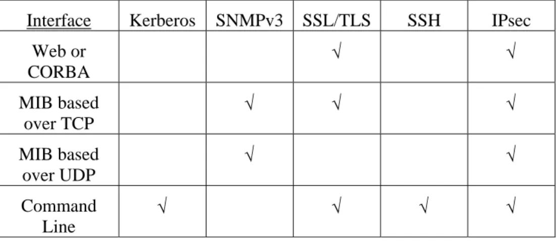
To summarize, Table 1 shows the variety of choices for protecting various management interfaces. A ‘√’ indicates that the specified protocol can be used to protect the specified interface. Because IPsec can be used in all of the identified cases and is the OIF’s choice for securing signaling protocols between NEs [Gra03], IPsec is the RECOMMENDED solution. This choice is consistent with the fact that IPsec is mandatory in IPv6 (see RFC 2460, [DH98]).
Table 1: Applicability of Security Solutions to Different Interfaces.
Interface Kerberos SNMPv3 SSL/TLS SSH IPsec
Web or CORBA √ √ MIB based over TCP √ √ √ MIB based over UDP √ √ Command Line √ √ √ √
6 Security Systems and Specifications
6.1 IPsec
6.1.1 IPsec Description
The architecture of IPsec is defined in [KA98a]. IPsec provides cryptographic security for protocols running over IPv4 or IPv6 with the ESP (Encapsulating Security Payload, [KA98c]), the AH (Authentication Header, [KA98b]), and cryptographic key
management protocols (IKE, [Pip98, MSST98, HC98]), which provide different security services. The AH transform protects IP datagrams by providing integrity with message authentication codes (MACs) and optional replay detection with sequence numbers. ESP provides not only the services of AH but also confidentiality with encryption.
Once an IPsec security association (SA) is established, datagrams can be sent and received securely. A SA, described by an entry in the security association database (SAD), specifies the security services used to protect the traffic carried within the SA. SAs are identified by <SPI, protocol, destination address>1, where “SPI” stands for
1
In the currently drafted IETF revisions (February 2003), only the SPI and destination address are used to identify a SA.
Security Parameters Index and “protocol” is either ESP or AH. IPsec determines whether to apply a SA to outbound traffic and what SAs to require for inbound traffic by
consulting the entries, called selectors, in the security policy database (SPD).
The parameters for an IPsec SA are typically established by a key management protocol2. These parameters include the encapsulation Mode (Tunnel or Transport), algorithms and modes of operation [NIST01], session keys, SPI value, and SA lifetime. IKE is a two-phase entity authentication and key management protocol3. It supports AH and ESP by establishing and managing the SAs in the SAD. IKE Phase 1 sets up an internal SA used to protect IKE Phase 2 cryptographic key exchanges. IKE Phase 2 creates IPsec SAs and their associated parameters and keys. IKE allows use of a flexible suite of public key and private key algorithms and has a number of attractive security features including forward secrecy, anonymity against eavesdroppers, and some protection against denial of service attacks.
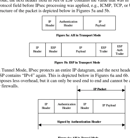
IPsec may operate in Transport or Tunnel Mode. When IPsec is used with IPv4, the protocol field in the IPv4 header contains the value for “ESP” or “AH.” In Transport Mode, the next header field in AH or ESP contains the value that was in the original IPv4 protocol field before IPsec processing was applied, e.g., ICMP, TCP, or UDP. The structure of the packet is depicted below in Figures 5a and 5b.
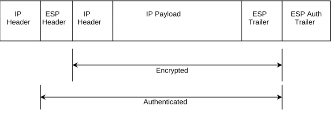
In Tunnel Mode, IPsec protects an entire IP datagram, and the next header field in AH or ESP contains “IPv4” again. This is depicted below in Figures 6a and 6b. Transport Mode imposes less overhead, but it can only be used end to end and cannot be applied at routers or firewalls.
2
IPsec has a mandatory provision for manual key distribution, but because manual key distribution does not allow for important functions like automatic rekeying, it is not recommended in this IA.
3
An Internet Draft for a revised and simplified version of IKE, called IKEv2, exists.
IP Header
IP Payload
Figure 5b: ESP in Transport Mode
ESP Header ESP Trailer ESP Auth Trailer IP Header IP Payload
Figure 5b: ESP in Transport Mode
ESP Header ESP Trailer ESP Auth Trailer IP Header Authentication Header IP Payload
Figure 5a: AH in Transport Mode
IP Header Authentication Header IP Payload
Figure 5a: AH in Transport Mode
IP Header IP Header Authentication Header IP Payload IP Packet
Signed by Authentication Header
Figure 6a: AH in Tunnel Mode
IP Header IP Header Authentication Header IP Payload IP Packet
Signed by Authentication Header
Figure 6b: ESP in Tunnel Mode.
Authentication of the parties using IPsec is implied by the possession of the integrity and confidentiality keys used by AH or ESP. Therefore, authentication is tightly linked to the key management protocol during SA establishment. Typically, certificates are used to verify digital signatures or to complete other public-key operations applied to the key management, and authentication is achieved by examining the issuer, subject name, and other pertinent information in such certificates, chains of certificates, associated
revocation lists, etc. Alternatively, authentication may follow from the use of IKE with pre-shared keys. Pre-shared keys require that the key value be administratively
configured into each such pair of peers in a secure, out-of-band manner.
The two mandatory integrity transforms are HMAC-MD5 or HMAC-SHA-1, in each case truncated to 96 bits. Use of AES-CBC MAC is also supported. The recommended
confidentiality algorithms are 3-DES in CBC mode, AES in CBC mode, and AES in counter mode.
6.1.2 Specifications for Using IPsec
The Security Extension for UNI and NNI [Gra03] describes the use of IPsec ESP and IKE
to protect control plane traffic (signaling, etc.) between NEs. If the OAM&P protocol used to access a NE runs (unicast) Internet Protocol (IP), then using IKE and ESP to protect this access channel is RECOMMENDED4. IPsec provides combinations of entity authentication, key management, datagram integrity, replay detection, confidentiality, and security policy management. Security policy management includes establishing security associations and enforcing their proper use.
Because IPsec is perceived to be complex to implement, a major goal of [Gra03] was to specify a simplified profile of IPsec. This section uses [Gra03] to specify how NEs can protect IP-based OAM&P protocols (command line, web, CORBA, SNMP, or other interfaces running over IP) with the same mechanisms and as few differences as possible. However, in this IA the communications are always between a NE and a Management
4
Even in cases where the OAM&P protocol does not run over IP, it may be possible to protect a portion of the communications path tunneled over an IP network with an IPsec VPN. This particular configuration is out of scope, because it poses no requirements at the NE.
IP ESP IP IP Payload ESP ESP Auth Header Header Header Trailer Trailer
Encrypted
System, not between a pair of NEs, and the protocols being protected are used for OAM&P applications rather than for signaling and services associated with signaling. Implementations protecting OAM&P protocols with IPsec MUST satisfy the
requirements in Section 3 of [Gra03] as clarified and modified herein:
• Section 3.1, Configuration and System Security Issues.
Apply this section without any changes or additional specifications.
• Section 3.2, General Requirements.
The exact Transport Mode selectors are determined by the OAM&P protocol(s) and port(s). The NE MUST support the ability to limit access so that only permitted traffic is sent over IPsec. It is possible to use a single SA pair in either mode to protect more than one OAM&P protocol. The discussion of discovery protocols does not apply, but the requirements for auditing and using multiple SA pairs do apply.
• Section 3.3, Transport Mode versus Tunnel Mode.
Apply this section without any changes or additional specifications.
• Section 3.4, DHCP and NAT Traversal.
Apply this section without any changes or additional specifications. The connection between NEs in [Gra03] is a connection between a NE and a Management System in this IA.
• Section 3.5, Use of IKE.
Apply this section without any changes or additional specifications. The discussion of protecting UNI or NNI applies, in this case, to the applicable OAM&P protocols.
• Section 3.6. Rekeying.
Apply this section without any changes or additional specifications. In addition, note that expired SAs MUST NOT be used. Prior to expiration of an SA, a new SA MUST be established so that the management traffic can be switched over to the new SA prior to the expiration of the original SA. Keep-alive or Hello messages MAY be used for periodic communications to keep the SA from being prematurely torn down due to idleness when management traffic is not being transmitted.
• Section 3.7, Transforms.
Apply this section without any changes or additional specifications.
• Section 3.8, IPv4 Fragmentation.
Apply this section without any changes or additional specifications.
• Section 3.9, Security Policy Enforcement.
Apply this section without any changes or additional specifications.
• Section 3.10, Naming.
Apply this section without any changes or additional specifications.
• Section 3.11, Authentication.
Again, as in [Gra03], if certificates are used, these MUST be machine certificates, not user certificates.
• Section 3.12, System Issues.
6.2 SSL
and
TLS
6.2.1 SSL and TLS Description
The Secure Sockets Layer (SSL) and Transport Layer Security (TLS) protocols provide cryptographic authentication, data stream integrity, and data stream confidentiality for TCP connections. For more information, see [Resc01]. SSL and TLS are particularly well suited for protecting http traffic between web browsers and servers, but they may be used to protect any protocol running over TCP (e.g., telnet, rlogin, or even SNMP).
6.2.2 Specifications for Using SSL and TLS
In typical e-commerce applications, the initial burden of authentication is placed on the server, because the browser can supply the required payment credentials like credit card data when needed. For applications like network management, initial authentication of both parties is critical. One method is to outfit both parties with certificates signed by the network operator’s designated CA, install that CA’s root certificate in the clients and servers, and remove all other trusted root certificates from the clients and servers. That is, both parties (when using RSA, for example) respond to the CertificateRequest message with a Certificate message and a CertificateVerify message. A simpler and acceptable alternative method of client authentication is to use a hardware-token-based one-time password system over every new, secured connection. Simple passwords sent over the secure connection may be vulnerable to a number of practical attacks, so these should be used only with carefully constructed constraints (aging, complexity, logging, protection against dictionary attacks, etc., see [T1M1]).
• A NE or Management System that provides an HTTP server protected by SSL or TLS MUST support SSLv3 with RSA [FCK96]. It MAY also support SSLv3 with DSS and DH and it SHOULD support TLS 1.0 [DA99]. (Users may refer to [BW03] for extensions to TLS that may be included in a future version of this IA.) Other protocols (e.g., SSLv2, PCT, and S-HTTP) are outside the scope of this document. • Clients (e.g., browsers) MAY use certificates to authenticate to the server. They
MAY, however, use a token-based authentication system or passwords sent over the protected channel.
• When using certificates, certificates SHOULD be generated with a lifetime of no more than two years. Entire certificate chains MUST be checked for correct names, and expiration and SHOULD be checked for revocation.
• Both parties MUST have access to a source of cryptographically strong random or pseudo-random numbers. See [Gut98] and [KSF99] for additional guidelines and recommendations.
• The server MUST support RSA; it MAY support DH-DSS; it MAY support Kerberos
as described in [MH99]; and it MAY support the Fortezza cipher suites, but see [Resc01] for a discussion of limitations using Fortezza as described in [FCK96]. For RSA or DH-DSS, key lengths MUST be at least 1024 bits and both servers and browsers SHOULD support longer keys for these algorithms, up to 2048 bits. The same is REQUIRED for all certificates in the chain. Applications requiring
confidentiality SHOULD use 3-DES or AES-128. RC4-128 MAY also be supported. Proprietary cipher suites MAY also be used.
• Both parties MUST provide long-term protection for the privacy of their
authentication data and the integrity of root public keys they rely upon to verify certificates. Hardware tamper resistance (e.g., a smart card or cryptographic module) is preferable to disk storage, but if disk storage is used, these items SHOULD be encrypted and password protected, and the system SHOULD log all attempted accesses securely.
• Both parties MUST protect pre-master secrets, master secrets, and session keys for the duration of their use and destroy them directly thereafter. Use of software that allows unrestricted access to main memory, memory dumps, examination of paging devices, and so forth MUST be restricted accordingly. Processes SHOULD be locked in main memory and not paged wherever practical.
• Session resumption with a timeout MAY be used. The RECOMMENDED timeout
interval is ten minutes.
6.2.2.1 Specifications for Using SSLv3
• A NE that supports the SSLv3 protocol (protocol version major=3, minor=0) MUST support it as defined in [FCK96].
• Port and protocol selection and use MUST follow [Resc00].
• The ephemeral RSA, anonymous, and Server Gated Cryptography options MUST
NOT be used.
• The server MUST use the close_notify alert. The browser SHOULD also use close_notify to complete a two-way closure handshake.
• Both parties SHOULD support protected Rehandshake exchanges. 6.2.2.2 Specifications for Using TLS 1.0
• A NE that supports the TLS protocol (protocol version is major=3, minor=1) MUST support it as defined in [DA99]. (Use of the TLS extensions in [BW03] are not precluded by this specification.)
• If TLS 1.0 is supported, the requirements for connection closure, use of port numbers, checking the server’s identity, and checking the client’s identity in [Resc00] MUST be followed.
• If TLS 1.0 is supported, the name matching rules specified in [HFPS99] MUST be followed.
• Servers SHOULD and browsers MAY support the use of port numbers described in [KL00].
6.2.2.3 Securing the Browser
This section applies to the client software (i.e., browsers) used with SSL or TLS to protect HTTP-based OAM&P access to a NE.
• Newer browsers (released in 2000 or later) MUST be used instead of older ones, because older protocols like SSLv2 have security defects, and cryptographic strength has increased since the easing of U.S. export restrictions in January 2000. For the same reason, U.S. export-only versions SHOULD NOT be used.
• The browser SHOULD be configured with its security settings to support the specifications listed above. If features such as plug-ins, Java, JavaScript, ASP, or ActiveX controls are not used, they SHOULD be disabled. If such features are used, their potential vulnerabilities SHOULD be understood and mitigated. Unneeded CAs’ certificates SHOULD be removed. The browser and the platform on which it is running SHOULD be isolated from the possibility of unauthorized modification. Extraneous network services SHOULD be disabled. System logging and intrusion detection tools SHOULD be used to monitor the configuration as appropriate. • The browser SHOULD wait for the server’s handshake Finish message before
sending application data.
6.3 SNMPv3
SNMPv1 and SNMPv2 offer limited security and therefore SNMPv3 may be used as it provides encryption and authentication as part of the core protocol. SNMPv3 with user based security model recognizes three levels of security:
1. Without authentication and without privacy (noAuthNoPriv) 2. With authentication but without privacy (authNoPriv)
3. With authentication and privacy (authPriv)
This section describes security for an interface between a NE and Management System that uses MIB-based network management running SNMPv3.
6.3.1 SNMPv3 over Different Transport Layers
A NE that supports SNMPv3 access over TCP MUST support one of the following: • SNMPv3 as described below in Section 6.3.2,
• SSL-TLS as described in Section 6.2.1,
• IPsec as described in Section 6.1.1, which, in this case, is RECOMMENDED. A NE that supports SNMP access over UDP MUST support one of the following: • SNMPv3 as described below in Section 6.3.2,
• IPsec as described in Section 6.2.1, which, in this case, is RECOMMENDED. A NE that supports SNMP access over protocols other than TCP and UDP MUST support:
• SNMPv3 as described below in Section 6.3.2. 6.3.2 SNMPv3 Description
SNMPv3 is defined in [HPW00], [CHPW00], [FLRW03], [LMS00], [WB00], and [WPM00]. It provides for message integrity, confidentiality, a freshness window, and a
strong model for authorization and access control. Parties are authenticated by the possession of shared keys. The SNMPv3 specification names DES-CBC as the only confidentiality algorithm, but newer alternatives have been proposed. For message authentication and data integrity, the SNMPv3 specification lists HMAC-MD5-96 as “shall support” and HMAC-SHA-96 as “should support.” SNMPv3 provides a timeliness feature only if authentication is used. The complete SNMP message is checked for integrity, so in conjunction with authentication the timeliness values will be considered trustworthy. SNMPv3 specifies a time window of 150 seconds within which SNMP messages shall be received after the time they are sent. To avoid delay and replay attacks, messages without recent time indicators are not considered authentic. The time of the SNMP engine is indicated by two values taken together, snmpEngineBoots and
snmpEngineTime. These two values are included in an authenticated message sent to or received from a SNMP engine. Upon receipt, the values are checked to ensure that the indicated timeliness value is within the acceptable time window.
Again, as with synchronization, timeliness checking is only done if the authentication service is in use and the message is authentic, thus assuring the validity of the message header fields.
Many SNMP implementations make use of proxy agents. SNMPv3 specifies that a proxy forwarding application, “must perform a translation of incoming management target information into outgoing management target information. How this translation is performed is implementation specific.” This implies that proxy agents shall have access to the SNMP packets. Therefore, the proxy agents need to have access to privacy keys and authentication keys. A secured path between a Management System and a NE may include several proxies processing plaintext messages in the path. In fact any proxy agent in the path may translate a secure message into an insecure message.
SNMPv3 contains no provision for security association negotiation or session key generation. Although SNMPv3 does provide guidelines for the creation, update and management of the keys, the keys are not accessible via SNMP. SNMPv3 assumes that the caller will select the proper key to use for each service and will somehow have distributed the key in a secure manner to all SNMP engines that require it.
SNMP is not considered to have a requirement covering DoS, because a DoS attack is likely to disrupt all types of communication exchanges, with which the overall security facility, not just that for the management infrastructure, should be concerned and therefore have taken protective and preventive measures against.
6.3.3 Specifications for Using MIB-Based Management–SNMPv3
• Implementations MUST support DES-CBC and SHOULD support 3DES-CBC and
AES-128-CBC.
• Entities implementing the rekey option MUST have access to a source of cryptographically strong random or pseudo-random numbers. See [Gut98] and [KSF99] for additional guidelines and recommendations.
• The key localization algorithm transforms the user’s password into a traffic encryption key shared between a user and one authoritative SNMP engine.
Implementations of SNMPv3 using an auxiliary key management scheme like Kerberos or IKE MUST NOT use the key localization algorithm option.
• SNMPv3 implementations using the integrity option SHOULD use the timeliness feature.
• Access control lists MAY be used to restrict the IP address from which different SNMP messages are sent.
• SNMP agent logging MAY be enabled.
6.4 Secure Shell (SSH)
6.4.1 SSH DescriptionThe Secure Shell (SSH5) defines security protocols that use public key cryptography to establish secure, authenticated sessions between a client and a server.
SSH1 [Yl96] and SSH2 [Car01] are two completely distinct protocols. Both have freely available specifications and have been implemented in freeware and commercial
products. Neither is a standard, although SSH2 was described at the time of this writing (November 2002) in several Internet Drafts [Yl02a, Yl02b, Yl02c, Yl02d]. Because SSH1 and SSH2 servers bind to the same TCP port, and the protocol begins with an exchange of protocol and software version numbers, it is possible for a SSH2 server to launch a SSH1 server to handle a SSH1 client.
SSH is intended to allow a user to logon, execute commands, or transfer files securely. It is a replacement for telnet, rlogin, rsh, and rcp. It provides strong authentication and secure communications. An integrated “port forwarding” feature can be used to secure X11 connections or in fact any TCP connection, e.g., to perform a secure remote backup. SSH2 has an explicit capability to secure ftp as well.
A description of SSH begins with the transport layer protocol. In SSH1, two levels of public keys are used. A client sends an authentication request to a server, and the server responds with its long-term public host key and public server key (which changes
hourly). In SSH2, only the host key is present. The client compares the host key, which in the former case authenticates the server key, with that which has already been configured. A client may be configured to trust new host keys or not. Note that certificates are not used currently by SSH, but use of a PKI and a device certificate per NE may be added in the future. To make sure that these first two messages of the key exchange sequence itself have not been manipulated, both parties compute a hash of the initial messages and session key, which they use later as a session identifier.
After the client receives and verifies the server’s public key(s), it chooses a 256-bit pseudorandom number, which becomes the basic shared secret from which all uni-directional session keys are derived. The random number, a known constant, and the session identifier are double encrypted with the server and host keys in SSH1 or singly encrypted with the host key in SSH2. This value is returned along with a choice of traffic
5
SSH is a registered trademark and Secure Shell is a trademark of SSH Communications Security Ltd. of Finland.
protection algorithms. In SSH1, this provides perfect forward secrecy for the traffic confidentiality keys with respect to the host key.
SSH provides for the negotiation of both traffic protection and compression algorithms. SHA-1 and 3-DES are mandatory to implement, but other popular choices as well as proprietary algorithms can also be used. A reliable transport stream in each direction (i.e., TCP) is required, and packet sequencing is additionally verified by including an implicit sequence number in each MAC calculation. Either party may request rekeying at any time.
The SSH authentication protocol is layered on top of the transport layer protocol. The next step is user authentication, which can be done with a password over the secure channel, token-based systems, or the user’s public-private key pair. In the last of these cases, a pass-phrase protects the user’s private key on the client system. (SSH1 also supports Kerberos for user authentication). After the authentication protocol completes successfully, the client may request different protected services from a list of supported services. These services are then protected with SSH encryption, MACs, and secured with end of file messages.
6.4.2 Specifications for Using SSH
Note: An OAM&P interface between a NE and a Management System MAY be secured by running an application-layer protocol such as secure telnet, SFTP (Secure FTP), or SCP (Secure Copy) on top of SSH, so long as the underlying SSH layer follows the specifications below.
The following specifications are provided for the use of SSH to protect the management of a NE.
• Official releases of the software from SSH Communication Security are signed. Implementers or users downloading these releases of SSH SHOULD verify these signatures.
• SSH2 contains improvements in performance, security, and portability over SSH1. In particular, certain active attacks against the SSH1 protocol are prevented in SSH2. Therefore, client and server implementations SHOULD support SSH2.
• Implementations of SSH clients and servers MUST use a cryptographically strong method of generating pseudo-random numbers. See [Gut98] and [KSF99] for additional guidelines and recommendations.
• Deployments of SSH SHOULD use public key authentication. The public key MAY be that of a specific user’s account or the NE. Deployments MAY use passwords or, in the case of SSH1, Kerberos. Host-based authentication SHOULD NOT be used. • Client computers MUST be protected from attempts to modify their configured host
keys or to obtain their private keys. Such protection includes physical access to and modification of the software, as well as other compromises.
• Clients MUST NOT accept new, not configured host keys for access to NEs.
• SSH servers MUST be protected so that host private keys are not revealed and, in the case of public key authentication, users’ public keys are not altered. If passwords or
another type of authentication is used, such authentication data MUST also be protected appropriately to avoid both direct attacks and dictionary attacks. • SSH SHOULD NOT be configured with public key sizes shorter than 768 bits. • If a NE runs a SSH server, it MAY be configured with a SSH client as well.
• In UNIX-based implementations, the server (sshd) SHOULD be run directly and not from inetd. It MAY be configured with TCP Wrappers.
6.5 Kerberos
6.5.1 Description of Kerberos
Kerberos is a trusted-third party security system that uses a Key Distribution Center (KDC) to establish secure, authenticated sessions between a client and an application server. Kerberos runs at the application layer, so, if Kerberos is used, it requires software support in the applications on the client and the NE. Each client and each application server have a long-term shared secret established with the KDC. Clients initiate secure communications with Applications Servers by requesting “tickets,” which contain the keying material and other credentials needed