HAL Id: inria-00387127
https://hal.inria.fr/inria-00387127
Submitted on 24 May 2009
HAL
is a multi-disciplinary open access
archive for the deposit and dissemination of
sci-entific research documents, whether they are
pub-lished or not. The documents may come from
teaching and research institutions in France or
abroad, or from public or private research centers.
L’archive ouverte pluridisciplinaire
HAL
, est
destinée au dépôt et à la diffusion de documents
scientifiques de niveau recherche, publiés ou non,
émanant des établissements d’enseignement et de
recherche français ou étrangers, des laboratoires
publics ou privés.
General Specular Surface Triangulation
Thomas Bonfort, Peter Sturm, Pau Gargallo
To cite this version:
Thomas Bonfort, Peter Sturm, Pau Gargallo. General Specular Surface Triangulation. Asian
Confer-ence on Computer Vision, Jan 2006, Hyderabad, India. pp.872–881. �inria-00387127�
General specular Surface Triangulation
Thomas Bonfort, Peter Sturm, and Pau GargalloMOVI - GRAVIR - INRIA - 38330 Montbonnot, FRANCE
http://perception.inrialpes.fr
Abstract. We present a method for the reconstruction of a specular surface, using a single camera viewpoint and the reflection of a planar target placed at two different positions. Contrarily to most specular sur-face reconstruction algorithms, our method makes no assumption on the regularity or continuity of the specular surface, and outputs a set of 3D points along with corresponding surface normals, all independent from one another. A point on the specular surface can be reconstructed if its corresponding pixel in the image has been matched to its source in both of the target planes. We present original solutions to the problem of dense point matching and planar target pose estimation, along with reconstruction results in real-world scenarii.
1
Introduction
Reconstructing surfaces from images usually relies on the identification and matching of pixels corresponding to a same 3D point on the surface. On un-polished surfaces, matching can be fulfilled by analyzing surface texture, and assuming that identical texture patches correspond to identical points on the surface. In the case of specular surfaces, the apparent surface texture is the re-flection of the object’s surroundings, being de facto viewpoint-dependent, thus invalidating the geometric constraints used by all non-specific reconstruction al-gorithms. Even standard laser scanners are unable to acquire specular surfaces, as all of the laser energy is reflected symmetrically to the normal of the surface, and therefore cannot be detected by the sensor [1]. Consequently, specularities, and even more importantly specular objects, are usually discarded as noise by most surface reconstruction algorithms. However, specular reflections give rise to strong constraints on surface depth and orientation, and we take advantage of these additional cues to reconstruct a precise model of the surface.
We describe a method recovering points of a specular surface, independently from one another. We assume an internally calibrated pinhole camera viewing the reflection of a planar target, and a dense matching of the camera pixels with the points on the target. While the camera is rigidly attached to the specular surface, we acquire images of the reflection of the target placed at two different unknown locations. The foundation of our method is closely related to the work on general (i.e.non central) cameras, as the reconstruction of the specular surface from the images of a calibrated camera is equivalent to the calibration of a non-central catadioptric system. The output of the algorithm is a collection of 3D points of
the specular surface, and the two transformations (rigid displacements) from the camera reference coordinate system to the target plane coordinate systems. 1.1 Previous Work
Though less actively than for lambertian surfaces, the reconstruction of specular surfaces from images has interested researchers in the field of computer vision for the past 20 years. For example, Blake and Brelstaff [2] study the disparity of highlights on a specular surface in a stereoscopic framework. Zissermanet al. [3] tracked the motion of specularities obtaining a degree-1 family of curvatures along the tracked path.
In [4], Oren and Nayar study the classification of real and reflected features, and recover the profile of a specular surface by tracking an unknown scene point. The work was extended to complete object models by Zheng and Murata in [5], who reconstruct a rotating specular object by studying the motion of the illumination created by two circular light sources.
Halstead et al., in [6], fit a spline surface to a set of normals, iteratively refining the result. Their method requires an initial seed point on the specular surface, and was applied to the sub-micronic reconstruction of the human cornea. The approach was extended by Tariniet al.[7] who integrate around a seed point, and use a global self-coherence measure to estimate the correct depth for the seed point. Under a distant light configuration, Solemet al. [8] fit a level-set surface with a variational approach.
Savareseet al.detail in [9] the mathematical derivations allowing the recovery of surface parameters up to 3rd
order from one view of a smooth specular object reflecting two intersecting calibrated lines, when scale and orientation can be measured in the images.
Bonfort and Sturm [10] present a space carving approach using surface nor-mals instead of color as a consistency measure.
1.2 Notation
The following notation will be used throughout the article: bold letters rep-resent a vector in 3D space, while italic letters represent scalars. Matrices are represented byCAPITAL letters.
2
Approach
Suppose a calibrated pinhole camera located atOc=0Tobserving the reflection
in an unknown specular surface of a known 3D feature Q. As the camera is calibrated, recovering the position of the surface at the point pof reflection is simply the estimation of its depth along the corresponding projection ray. This already constrained scenario is still insufficient in order to obtain a solution to the depth estimation, as for every point Palong the projection ray, we can compute a surface orientation that would produce an identical observation: depth
estimation of a point on a specular surface from one image gives rise to a one dimensional solution, function of surface depth and orientation.
Now consider the same setup, except that for a given camera pixel p, two 3D point correspondences Q1 and Q2 are given. This constraint is sufficient
to uniquely determine the depth of the specular surface at p, namely as the intersection of the lines formed by the camera’s projection center andpon the one hand, andQ1and Q2on the other.
If we consider the ( camera + specular surface ) system as a general camera, finding two pointsQ1 andQ2for eachp, and therefore obtaining a
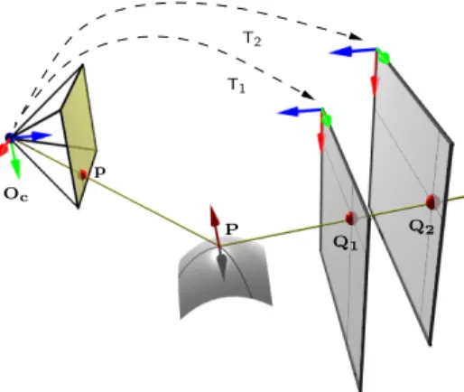
reconstruc-tion of the surface, is equivalent to calibrating this camera, as this is usually done as a one-to-one mapping of image pixels with lines in 3D space. In [11] or [12], such a calibration is achieved by using points on calibration planes: pix-els in the image are matched with their 2D correspondent in the target planes, then the only step necessary in order to obtain 3D coordinates of these points is to estimate the pose of the planes in the camera reference coordinate system. Figure 1 summarizes our reconstruction method for 3 point correspondences: reconstructing the specular surface sums down to matching camera pixels with their source in the target planes, then estimating the two transformation matri-ces T1and T2, that map points from the target reference coordinate system to
the camera one.
P Q2 Q1 Oc T1 p T2
Fig. 1: Reconstruction Approach. Matching of image pixels with their source in the targets and estimating two plane poses is sufficient to reconstruct the surface.
3
Dense Matching
The 3D position of a point on the specular surface corresponding to a given pixel in the camera image plane can only be computed if a correspondence can be found in both of the target planes. As such, in order to obtain a dense
reconstruction of the specular surface, each pixel of the specular surface must be matched to its target correspondence.
3.1 Initial Matching
We use a standard computer monitor displaying Gray codes, once original and once inverted [13]. The total number of images taken for each pose of the target is therefore twice the binary resolution in each direction.
The resolution of the codes and the width of the low order stripes must be chosen according to the shape of the specular object and the resolution of the camera. Too high resolution codes tend to be blurred out and become unusable, whereas too coarse ones lack in precision. In most cases, multiple pixels in the camera image correspond to the same code in the target planes. Figure 3 (top right) shows the result of a reconstruction if we apply this initial matching directly.
3.2 Sub-pixel Matching
From the Gray code decoding we get an initial integer-valued estimate of the pixel matching. To get more accurate correspondences, this initialization has to be refined. Let u(x, y) and v(x, y) denote the coordinates of the target point corresponding to the camera pixel (x, y). Instead of directly smoothinguandv
as in [13], we use an energy minimization approach to ensure that the smoothed correspondences will still link camera pixels with their corresponding origin on the target planes.
We minimize the following energy functional with respect touandv:
E(u, v) =X k Z Ω (Gk(u, v)− Ik(x, y)) 2 dx dy +λ Z Ω |∇u|2 +|∇v|2 dx dy
whereΩis the mirror image region,Gk are the Gray code images andIk are the images captured by the camera.
The first energy term is the data term. It penalize correspondences for which the color Ik(x, y) captured by the camera and it’s corresponding Gray code
Gk(u, v) are not the same. We first scale the camera images intensities pixel-wise, so that 0 and 1 intensities correspond to pure black and pure white. This referential is computed by displaying entirely black and entirely white images on the planar targets. For non-integer values of uand v,Gk(u, v) is computed using bilinear interpolation.
The second term is a homogeneous regularizer. It penalizes large variations on the correspondence functions. Theλparameter sets the compromise between data evidence and smoothing.
The energy functional is minimized by a steepest descent. The descent direc-tion is given by the Euler-Lagrange equadirec-tions,
∂ui ∂t =− X k 2(Gk− Ik) ∂Gk ∂ui +λ2∆ui foru1=uandu2=v.
Figure 3 (bottom right) shows the result of the reconstruction after having smoothed the orginal matches.
4
Target Pose Estimation
Our reconstruction algorithm requires knowledge of the relative pose between the camera and target plane, in its different positions.
The first and simplest method is to ensure that the target plane is partially visible in the camera, as seen in figure 3, and apply any pose estimation method [14]; we use the method proposed in [15].
To ensure a much higher flexibility, we wanted to be able to work with se-tups where the camera hasn’t any direct view of the target plane; if this was possible then one would be able to take “better” images of the specular surface to be reconstructed. The second solution is to estimate the pose of the targets through the reflection by a known mirror. We therefore suppose having a means of estimating the pose of the planar mirror: this can either be done by placing markers on the mirror and performing a classical plane pose estimation, or in our case by using a hard-drive platter, whose known interior and exterior radii allow an ellipse based pose to be estimated. More details on the reflection by a known plane can be found in the next paragraph.
4.1 Pose Through Reflection by 3 Unknown Planes
We acquire images by holding a planar mirror in front of the camera in different positions, such that the target plane’s reflection is seen by the camera. We now briefly describe how to solve the relative pose between camera and target plane, from three or more such images, or one image of three or more such mirrors.
In the following, we adopt a global reference frame such that the target plane is atZ= 0, and first carry out a pose estimation for each image, as if the image were a direct view of the target plane.
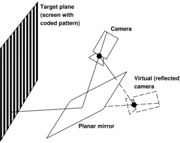
This procedure gives us the pose of the virtual camera that would be pro-duced by reflecting the real camera in the planar mirror, cf. figure 2. If we knew the pose of the planar mirror, we could of course immediately recover the cam-era’s true pose, as follows. Let the recovered pose of the virtual camera for image
ibe given via the projection matrix:
Pvi ∼Si I| −ti
Target plane (screen with coded pattern) Camera Planar mirror Virtual (reflected) camera
Fig. 2:Reflected pose. The estimated pose of a reflected plane is equivalent to its pose viewed from a virtual reflected camera.
whereSi is a reflection matrix (a rotation matrix multiplied by−1), and let the
associated pose of the planar mirror be represented by homogeneous coordinates
Πi∼
ni
di
where we distinguish the plane’s normal vectorni(of unit norm), and its distance
di from the origin. The true camera’s pose can be recovered by multiplyingPvi with the transformation modeling the reflection in the planeΠi:
Pi∼Pv i I−2ninTi −2dini 0T 1 (1) ∼Si I−2ninT i| −ti−2dini
We now have to address the question how to recover the true camera’s pose, knowing that with the correct mirror positions Πi, the camera poses Pi com-puted according to (1), have to be equal to one another: Pi ∼ Pj. Due to
det I−2ninTi
= detSi = −1, we can safely eliminate the scale ambiguity
in the equationPi∼Pj, and obtain element-wise equalities:
∀i, j:Si I−2ninTi=Sj I−2njnTj (2)
∀i, j:Si(ti+ 2dini) =Sj(tj+ 2djnj) (3)
Computing mirror plane normals ni. LetXi=I−2ninTi, which is of course a symmetric matrix. From (2), we get:
Xi=STiSj
| {z }
Rij
Furthermore,Xj is a reflection, i.e.XjXj =I, therefore:
Rij=XiXj (5)
Letaij be a vector orthogonal toni andnj. We therefore have:
Rijaij =XiXjaij = I−2ninTi I−2njnTj aij = I−2ninTi aij =aij
which implies thataij is the eigenvector to the eigenvalue 1 ofRij,i.e. thataij is the rotation axis ofRij.
We now have the means to compute all mirror normalsni, provided at least 3 mirrors are used.
1. Compute the pose eq. (1) of all virtual cameras, as described above. 2. For all pairs of mirrors (i, j), compute Rij, as per eq. (4). Compute their
eigenvectors to the eigenvalue +1, i.e. vectorsaij. 3. For every mirror i, stack all aT
ij (respectively aTki) in a matrix A of size (n−1)×3 (wherenis the number of mirrors), and computeni as the unit eigenvector to the smallest eigenvalue ofATA.
Computing the true camera’s pose. The last step is to compute the least squares solution for thediof the linear equation system composed of one equation (3) per pair of mirrors. The system’s design matrix is of size 3n(n−1)×nand very sparse.
We now know all mirror planesΠi, and can compute the camera pose from any one of them, according to eq. (1). In practice, we do this computation for every mirror, and then “average” the resulting rotation matrices and position vectors that represent camera pose. We then apply a bundle adjustment style procedure for simultaneously optimizing the pose of the camera and the planar mirrors. The cost function minimized here is the reprojection error of target points, projected in the camera after reflection in the mirrors.
5
Optimization
In practice, we also perform a global non-linear optimization of the poses T1
and T2 of the target planes, before the triangulation. The cost function to be
minimized is the distance between matching lines in 3D space which we minimize using a Levenberg Marquardt algorithm.
cost(T1,T2) = X
i∈{matches}
6
Results
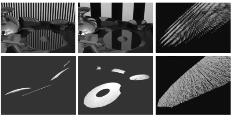
We tested our reconstruction method on real specular surfaces, using the different pose estimation methods presented in section 4. As seen on figure 3, no continuity or regularity is assumed.
Fig. 3:Validation Setup and Results.The top row shows two of the images used for the reconstruction. Notice the 3 curved mirrors (an ice-cream cup and two small wide-angle rear-view mirrors, the planar hard drive platter, and a direct view of the target plane, in the upper part of the image. The second row shows the reconstruction viewed from two locations. The model contains over 525 000 independent points. Note the planarity of the reconstructed hard drive platter in the left image. Only a few points could be computed on the ice-cream cup, as its surface covered by the exploitable Gray codes was limited. The two small rear-view mirrors (one with circular, the other with rectangular based shape) were completely reconstructed (apart from a non specular dent in the circular one). The two images on the right show the effect of the sub-pixel matching and constrained smoothing: top image shows result using raw gray codes, while the bottom one shows results after the smoothing step.
Having no ground truth results, we evaluated the correctness of the method by fitting a plane to the part of the reconstruction we knew was planar,i.e.the hard drive platter (linear least squares fitting, without outlier removal). In the reconstruction shown on figure 3, over 98% of the computed points were less than 0.2 mm away from the surface, and 64% less than 0.1 mm. The approximate diameter of the reconstructed part of the platter was 80 mm, resulting in a maximum 0.3% relative error in the reconstruction.
The accuracy of the reconstruction also depends on the quality of the pixel matching. Indeed, when experimenting with purely piecewise planar surfaces, where the sub-pixel matching was ”easy” to compute, the distances to the fitted planes dropped down to 99.9% of the computed points less than 0.1 mm away from the surface, and 88% less than 0.05 mm. This is because the average quality of the matches is higher compared to when the scene also contains curved spec-ular surfaces. Hence the pose of the target planes and finally the reconstruction are more precise.
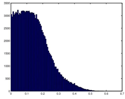
We tested the reconstruction on another setup composed only of planes with the different pose estimation techniques presented in section 4. Although the initial estimation of the poses given by the different techniques are not exactly identical, the non-linear optimization converged to very similar poses in all cases. The histogram of the point-plane distance, with the poses estimated with the three unknown planes (section 4.1), without global optimization, can be seen in figure 4. 0 0.1 0.2 0.3 0.4 0.5 0.6 0.7 0 500 1000 1500 2000 2500 3000 3500
Fig. 4:Point-plane distance.Histogram of the distance in of each point to the linear least squares fitted plane (in millimeters) with the poses estimated with the three unknown mirror planes (section 4.1).
Fig. 5:Real World Reconstruction.Reconstruction of a car windshield. The method allowed us to easily obtain a 800 000 + point model using a classical video projector, on a large scale reflective surface. The hole in the middle is due to a non-specular patch on the surface.
7
Conclusion
We have presented a novel method that reconstructs a specular surface from two views. Compared to other reconstruction methods, we attain a high level
of accuracy, without having the need to suppose surface continuity or regular-ity. We believe it could easily be implemented in an industrial surface inspection application, at least to provide an accurate initialization for integration based re-construction methods, probably the only purely vision based ones able to detect surface micro-structure. We also proposed a novel method for the pose estima-tion of a target plane even if it is never directly seen in the images, requiring the view of its reflection through unknown planar mirrors.
The drawback of the method is the need to obtain a dense matching over the complete surface we want reconstructed. This in practice is difficult to obtain with only two positions of the target plane, meaning multiple reconstructions have to be computed then stitched together.
References
1. Chen, F., Brown, G.M., Song, M.: Overview of three-dimensional shape measure-ment using optical methods. Optical Engineering39(2000)
2. Blake, A., Brelstaff, G.: Geometry from specularities. In: Second International Conference on Computer Vision (Tampa,, FL), Washington, DC,, Computer Soci-ety Press (1988) 394–403
3. Zisserman, A., Giblin, P., Blake, A.: The information available to a moving observer from specularities. Image and Vision Computing7(1989) 38–42
4. Oren, M., Nayar, S.K.: A theory of specular surface geometry. In: International Conference on Computer Vision. (1995) 740–747
5. Zheng, J.Y., Murata, A.: Acquiring 3D object models from specular motion using circular lights illumination. In: Procedings of the Sixth International Conference on Computer Vision (ICCV-98). (1998) 1101–1108
6. Halstead, M., Barsky, B., Klein, S., Mandell, R.: Reconstructing curved surfaces from specular reflection patterns using spline surface fitting of normals. In: SIG-GRAPH 96 Conference Proceedings. (1996) 335–342
7. Tarini, M., Lensch, H., Goesele, M., Seidel, H.: 3D acquisition of mirroring objects. In: Research Report MPI-I-2003-4-001, Max-Planck-Institut fr Informatik (2003) 8. Solem, J.E., Aanæs, H., Heyden, A.: A variational analysis of shape from
specu-larities using sparse data. In: 3DPVT, IEEE Computer Society (2004) 26–33 9. Savarese, S., Chen, M., Perona, P.: Recovering local shape of a mirror surface from
reflection of a regular grid. In: European Conference on Computer Vision. (2004) 10. Bonfort, T., Sturm, P.: Voxel carving for specular surfaces. In: International
Conference on Computer Vision. (2003) 591–596
11. Grossberg, M., Nayar, S.: A general imaging model and a method for finding its parameters. In: International Conference on Computer Vision. (2001) 108–115 12. Sturm, P., Ramalingam, S.: A generic concept for camera calibration. In:
Proceed-ings of the European Conference on Computer Vision. Volume 2., Springer (2004) 1–13
13. Scharstein, D., Szeliski, R.: High-accuracy stereo depth maps using structured light. In: CVPR (1), IEEE Computer Society (2003) 195–202
14. Haralick, R., Lee, C., Ottenberg, K., Nolle, M.: Review and analysis of solutions of the three point perspective pose estimation problem. IJCV13(1994) 331–356 15. Sturm, P.: Algorithms for plane-based pose estimation. In: Proceedings of the
Conference on Computer Vision and Pattern Recognition, Hilton Head Island, South Carolina, USA. (2000) 1010–1017