CONVR2011, International Conference on Construction Applications of Virtual Reality, 2011
4D GRID-BASED SIMULATION FRAMEWORK FOR FACILITATING
WORKSPACE MANAGEMENT
Amir Elmahdi, Ph.D. Student Bauhaus Universität Weimar [email protected] I-Chen Wu, Assistant Professor
National Kaohsiung University of Applied Sciences [email protected]
Hans-Joachim Bargstädt, Professor Bauhaus Universität Weimar
ABSTRACT: The scheduling of Building construction includes a number of impact factors, which make it very complex, tedious and time consuming. This process includes the identification of different activities and the technological constraints between these activities. Then available resources have to be assigned to these activities to fulfill the project criteria time, cost and quality. Traditional methods of planning, such as 2D technologies including bar charts, network diagrams and other scheduling tools, which are typically methods for modeling the process of the project, still dominate the practice. These methods lack a representation of the attributes of the component installation and the spatial information. This leads to drawbacks during the execution of these tasks such as overlapping of work areas, reduction in productivity, safety hazards, long hauling paths and poor quality of work. This paper proposes a 4D grid simulation framework to address the dynamic nature of work space management. In addition, a simple building project is used as an example to demonstrate the applicability and feasibility of the grid-based simulation framework. This simulation framework executes only tasks which satisfy the requirement of the space availability. Considering this space concept valid, robust, and thorough, better work preparation, augmented by the proposed system, will improve work efficiency, eliminate conflicts on site and will finally contribute to robust construction schedules.
KEYWORDS: Workspace Management, Grid, 4D Visualization, Simulation, Optimization, Scheduling
1.
INTRODUCTION
Space is regarded as a limited resource on construction sites. As time elapse and work progress on site the requirements and the characteristics of work spaces (type, size, and work location), and the subsequent activities, which take place on those areas, change constantly in time and in three dimensions. So that it is not unusual for the parties involved not to compete on the available work spaces, potentially interfering with each another, or when the workspace of on-site personnel conflict with material stacking space. These kinds of activity space conflicts occur frequently, severely affecting the process and efficiency of construction and resulting in productivity loss [Wu and Chiu, 2010]. Furthermore, a spatial case study was conducted on a £6 million construction site at the University of Teesside signified that 30% of non-productive time on site due to the lack of detailed and space planning [Mallasi and Dawood, 2002]. Therewith, one of the main problems associated with construction operation on site is obviously the coordination and interaction of different trades and their requirements for multiple pieces of equipment, crew member, material, etc. for the foreseen schedule.
Since early the 90th the Center for Integrated Facility for Engineering (CIFE) in Stanford University has lead research projects in collaboration with construction industry related to 4D CAD and formalized the necessary construction knowledge to build 4D models. They have developed a methodology that guides project planners in generating 4D models from 3D product models. For instance, Collier and Fischer linked the temporal data to layers in a 3D CAD models through a commercial 4D simulation system called Construction Simulation Toolkit from Jacobus Technology, Inc. The output movie is shown in “Walkthru” [Collier and Fischer, 1996; Akinci and Fischer, 2000]. Their work has made rapid development in providing engineers with an effective tool to manage the coordination complexity of the site, especially in conveying the sequence of construction processes. Hsieh et al. state an increase recognition from the construction industry on the benefits of using the 4D technology for increased productivity, improved project coordination, and optimized on-site resources [Hsieh et al., 2006].
Significant work has been done on the work space modeling in the last decade. For instance, Akinci et al. formalize the general description of space requirement through a computer system. Their research efforts have advocated the use of space templates to represent the dimensional properties of work spaces. The development of the work space templates includes laborer space, equipment space, hazard space and protected space. By using 4D CAD, a user can automatically generate the project-specific work spaces according to schedule information and represent the work spaces in four dimensions with their relationships to construction methods [Akinci et al., 2002c]. Akinci et al. extended the concept of generated and assigned work space to construction tasks to include a 4D methodology to detect and analyze potential time-space conflicts [Akinci et al., 2002b]. Another approach proposed by Guo focuses on space availability due to time and scheduling. He integrates two typical tools, AutoCAD for space planning and Microsoft Project for scheduling to develop and represent the spatial planning in 2D. The user can define an occupancy structures in the CAD environment. By laying the layers over each other, spatial conflicts for a specific time can be detected. According to criteria such as the size or percentage of the overlapping areas, the overlapping duration and their share of the processing time is attempted, by which the severity of the conflict can be determined. He has developed appropriate strategies for conflict resolution [Guo, 2002]. Akbas proposes a geometry-based process model (GPM) that uses geometric models to create and simulate workflows and work locations. This method provides spatial insight into the planning of work spaces and space buffers for repetitive crew activities [Akbas, 2004]. However, all these researches could not fully address the dynamic nature of work space requirements. The workspace was assigned to a task or a collection of tasks such as install windows in the east side of the building, which remained in this position for the entire duration. That is to say, work spaces assigned and only updated, when the horizon period of planning (one week, two weeks, etc.) is expired. Winch et al. advocate the use of a one-week planning duration when carrying out spatial planning for the execution level. They have developed a methodology, which allows construction planners to interactively “mark-up” areas in “AreaMan” for task execution. Tasks are assigned manually in MS project to these drawn areas. Lastly, the analysis of construction operations achieved through the development of the “SpaceMan”, which allow users to identify the critical spaces and their relationship to the critical path. Furthermore, it can provide the user with suggestion to resolve time-space conflicts [Winch and North, 2006].
Therefore, we proposes a 4D grid-based simulation framework to overcome the shortcoming from previous research, which helps planners to organize the work space at the execution level of task prior to construction, to visualize the occupation level of the space model, and to update the occupation level of the space model within short notice. The paper is structured as follows: first we formalize the work space description as well as the data model for work space management. Next we describe the representation of work space and the proposed methodology to address the objective of this paper. Before we draw our conclusion and the future approaches, we demonstrate our concept in a simple case.
2.
WORK SPACE FORMULATION
Construction activities require a set of adequate workspaces to be executed in a safe and productive manner. The researches have been taken two distinctive attitudes to formalize work space requirements: zone generation and work space types. Zones have been used from different researchers to refer to the spaces or groups of spaces, which required by specific task to serve construction operation as working units. Shaked and Warszawski defined zone by their nature (horizontal and vertical), their designation, (basement, lobby, mechanical, office, elevator shaft etc.), and their location [Shaked and Warszawski, 1995]. Thabet and Beliveau have pioneered the research field of zone generation. They suggest to divide the floor into a number of zones and then broken down into work blocks. Resources (material, equipment, laborers, etc.) can then be allocated to these blocks [Thabet and Beliveau, 1994b]. Akbas proposes a geometry-based process model (GPM) uses two mechanisms for zone generation, namely decomposition and aggregation, to create and simulate workflows and work locations. On the other hand, recent researches on work space planning included this work based on their concept of the identification of the work space types approach by Riley et al. For instance, Riley in his theoretical proposal 4D model includes four types of work spaces, i.e. the physical work space; storage areas for materials; paths for materials; and access points for unloading materials onto building floors. He assumed that they are related to the production planning of multiple crews [Riley, 1998]. Furthermore, the research efforts from Akinci et al. have advocated the use of space templates to represent the dimensional properties of work spaces. The development of the work space templates includes laborer space, equipment space, hazard space and protected space. Using work space types provide project planners a flexible way to express the characteristics of configurations that are of interest of determining the work space requirements for individual trade as well as for different concurrent working trades. Therefore, this paper proposes the inclusion of the different types of work space required by a specific task that are based on the classification of the different types of spaces made by Bargstädt and Elmahdi [Bargstädt and Elmahdi, 2010]. In
CONVR2011, International Conference on Construction Applications of Virtual Reality, 2011 TaskID TaskName Duration StartedDate EndedDate Predecessors Task ObjectID ObjectName TaskID 3D Component LaborID Name Length Width Laborer MaterialID Name Length Width Material EquipmentID Name Length Width Equipment WorkspaceID TaskID TypeID TotalArea SpaceStatus GridID Temporal Workspace HazardID Name Length Width Hazard DebrisID Name Length Width Debris 0 act on * 1 0 WorkspaceID TaskID TotalArea SpaceStatus GridID Length Width Fixed Workspace * * required reserved
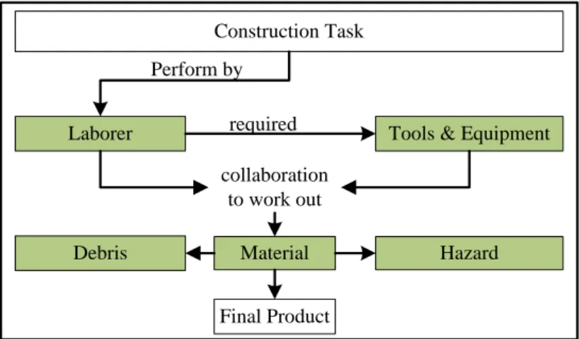
addition to the identification of work space types by Riley and Sanvido, we identify through site observations at different construction sites at the interior construction work a -debris work space-. Figure 1 illustrates the work space types we include in our model and how they interact with each other to perform a construction activity. We implement them in a simple case study specifically for trades at the interior construction work.
Figure 1: Formulation of work spaces
2.1
Data Model for Work Space Management
A clear structure of the database system with the 4D simulation framework is essential to couple different data types of data source and to serve a host of commercial users under different deployment environments. The data model for the work space management is a relational database schema, which mainly describes the relationships between the Task object (tasks with the schedule), the 3D Component object (components within 3D model) and the Work space object (types of work spaces). Figure 2 illustrates the structure of the database and how they will bind together within the system framework. The 3D Component object and the Task object are bound in one-to-many relationships through a unique ID (TaskID), where one or many tasks can act on one 3D component. This can lead to work space conflict, if two or more tasks have the same start date and act on the same object. There are two types of workspace are defined in this research. One is temporal workspace which is relating to time, workspace will be released when task is finished. Another on is fixed workspace, the specified workspace will be owned by building element forever. Thus the Workspace object regulates the relationship between the task object and 3D component. It identifies from one side the required workspace types for a specific task. On the other side the Workspace and the 3D component relationship ascertain the availability of the required work space.
Figure 2: Relationship between workspace, 3D component and task
Laborer Tools & Equipment
Material Debris Construction Task Final Product required Perform by collaboration to work out Hazard
2.2
Representation for Work Spaces
Kamat et al. state that the representation of construction operations depends on the level of detail and realism, and on the information required to be captured from the process [Kamat and Martinez, 2000]. They classify visualization into four groups: schematic 2D animation, 3D animation and 4D CAD visualization. Commercial 2D and 3D animation software have been used widely in manufacturing systems. But they are built based on process interaction on their simulation framework and so they are not effective for construction operation [Martinez and Ioannou, 1999] . Although, 4D CAD model support project planner in identifying and analyzing the bottlenecks of the project plan. However, 4 D CAD systems do not support visualization of construction operations that leads to the end product [Kamat and Martinez, 2001].
The literature in site layout planning provides valuable inspirations for explicit dynamic representations of space. For example, Hegazy and Elbeltagi have proposed a model to visually arrange required areas within a construction site [Hegazy and Elbeltagi, 1999]. This model represents any irregular user-defined construction site by dividing the site into two-dimensional grids. The size of the grid is determined as the greatest common divisor of all required areas. The required area can take on irregular shapes and is represented as multiple units of a grid, which are added up to make the required area. To define the position of any required area on the site, a location reference is formulated, which is used to define the starting position at which a required area is to be placed on the site. As well, non-orthogonal boundaries can be modeled using stepwise approximation. Later, Elbeltagi et al. improved this model to include health safety and productivity aspects with site layout analysis [Elbeltagi et al., 2004]. Another application is presented by Mawdesley et al. 2002. In their model, the positions and areas of all the facilities are shown in the form of grid units [Mawdesley et al., 2002]. AbouRizk and Mather have proposed a simulation concept for earthwork operations by connecting the simulation model with geometric models in external CAD software. The 3D CAD geometry is decomposed into a grid, where each grid element stores different information such as construction order, construction method, average depth, etc. [AbouRizk and Mather, 2000]. The advantages of a grid-based representation of required area are: a) it is feasible and easy to understand the occupation level of the site since space is graphically described; b) required area can be irregular or user defined shapes; and c) it increases the communication between model developers and users. Therefore, the 4D grid simulation framework implements the same concept to manage the available spaces, required spaces and the spaces in use (locked spaces) on production sites.
Many researchers advocate the need for 3D + t analysis of the work space [Koo and Fischer, 2000; Fischer and Kam, 2002; Akinci et al., 2002a]. Project planners wish to have the sense of the 3D space occupation, as well as the severity and the impacts of conflicts between two different trades and/or completed product overhangs, in order to decide upon the appropriate measurement on work processing. However, one of the current limitations of 4D graphic content is the level of granularity of 3D entities [McKinney and Fischer, 1997]. This limitation can be overcome by the proposed methodology in this paper. The occupation level of the model will be updated by the starting of a new event such as “task started” and/or by the ending an event such as “task finished”.
3.
4D GRID-BASED SIMULATION FRAMEWORK
3.1
Proposed Methodology
The procedure of the 4D grid simulation framework is a discrete event simulation framework. It outlines the search for a task that can be started for the current simulation time. Upon the occurrence of an event, all tasks do not start with the state to examine the performance of their technological constraints. Those tasks that meet their assigned constraints will be checked to verify their execution possibility to be started for the current simulation time. They are stored as the next executable tasks. The next executable tasks, which have satisfied their technological constraints are their status “not started” and has to be checked up on for the fulfillment of the spatial constraints. The identification of required work space associated with a specific task achieved through automatically synchronization of all 3D components via ID keys, that is to say the ID of the task will match with the ID of the 3D component and then verified the work space requirements. After we identified the required work space associated with specific task, the spatial constraint component verifies the availability of the required work spaces for the current task in a hierarchical structure. That is, first material, equipment space are verified for their availability, and then the laborer work space is verified for their availability with the space requirements of the tasks already being executed. On this basis, an evaluation will be made to avoid the possible overlap of the activities of required work spaces. The required work space, or rather, the required number of grids has to be locked during its execution. That
CONVR2011, International Conference on Construction Applications of Virtual Reality, 2011
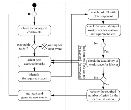
means these working spaces cannot be used by other work steps. After locking the required number of grids, the work step state changes from “task not started” to “task started”. Subsequently, the set of “task not started” task is checked to see if the required space is available by going to step one until no more work steps can be started at the current time. The simulation time is continuously checked during a simulation run. If the required time has expired, the work step status changes from “task started” to “task finished.” and is marked as finished. Its locked working spaces will be unlocked and can be used by other work steps. Figure 3 illustrates the procedure of the proposed methodology.
Figure 3: Procedure of the 4D Grid Simulation framework
3.2
System Framework
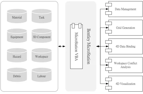
The implementation of the grid-based simulation framework was carried out in the MicroStation Visual Basic for Applications to acknowledge the work space requirements within the schedule. The system framework provides information platform that incorporate databases from different sources, that is data from different scheduling software such as MS Project, Primavera, etc., the 3D model from AutoCAD or BIM format and a built-in database for the different required work space types. Table 1 shows the color scheme implemented in this work. Figure 4 depicts the system framework, which include the following components to facilitate the dynamic nature of work space:
Data Management: is responsible to store the work space data and manage the requirement of the availability and the requirement of the work spaces associated with specific task.
Grid generation: allow the user to define the boundary of the working layout space i.e. site layout, floor layout. It also allows the user to specify the grid size or rather the number of grids in two directions across the plane of the layout. Thus two extra coordination will added to the points on the space layout namely the U-direction which is the direction in which the data points that defined each row were entered, and V-direction which is the direction in which the columns were defined.
4D Data Binding: is responsible to bind the different data of the system framework schedule, work space and the 3D component from the 3D model.
Workspace Conflict Analysis: this component support project planner with analysis the different types of conflicts.
4D Visualization: this component is responsible for visualization the processes leading to the end product, the end product as well as the occupation level of work space as well as conflict in 4D (X, Y, Z + time). It also shows how space conflicts occur between two different trades.
check technological constraints
identify the required spaces
start task and generate new events
select next executable tasks executable tasks ? waiting for next event
match task ID with 3D component
check the availiability of work space for material
and equipment, etc.
check the availabilty of work space for laborer
occupy the required number of grids for the
defined duration No Yes No Yes T as k c an n o t b e ex ec u te d T as k c an n o t b e ex ec u te d
Figure 4: System Framework Table 1: Color Schema
Free Workspace Equipment
Fixed Workspace Hazard
Laborer Debris
Material
4.
DEMONSTRATION
The case study is a high rise building composed of 5 floors. Our investigation is concentrated at the production “Floor Level”. Therefore, we limit our observation for one floor to demonstrate the applicability and feasibility of the grid-based simulation framework. The following five trades are modeled in the case study: plumbing as an example for the building services engineering trades, installation of interior doors and dry walls as an example of dry interior construction work, screed work and painting as an example for wet interior construction work. Figure 5 illustrates an overall representation of the implemented trades, representing the different objects. This simulation framework executes only tasks which satisfy the space requirements. The grid size is user defined according to the accuracy needed. The required work spaces are driven due to their installation positions, related work spaces (laborer, materials, equipment, debris, and hazard) and task dependencies so the impact of the interaction between the different trades and their work directions can be driven. We use different colors for the occupied number of grids for the different required work spaces by one trade (laborer, material, equipment, hazard and debris) as well as between different trades, thus we can clearly distinguish between the different concurrent working trades during the run of the simulation. For this purpose, we used different RGB values to generate a color corresponding to the individual trades.
Site Level Floor Level Plan View
Figure 5: A simple example Task 3D Component Workspace Labour Material Equipment Hazard Debris B en tle y M ic ro S ta tio n M ic ro S ta tio n V B A Data Management Grid Generation 4D Data Binding Workspace Conflict Analysis 4D Visualization
CONVR2011, International Conference on Construction Applications of Virtual Reality, 2011
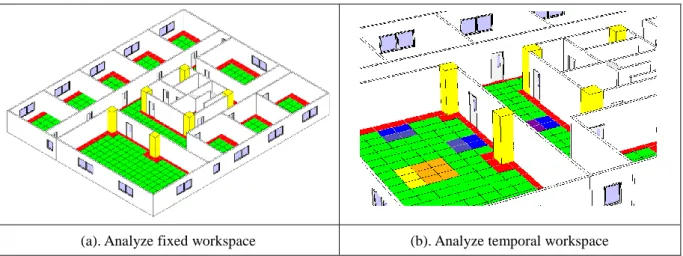
Figure 6 shows a snapshot from the one simulation run, which shows the occupation of the required number of grids for different trades with their specific work space requirements using different colors at specific time during the simulation experiment.
(a). Analyze fixed workspace (b). Analyze temporal workspace Figure6: A snapshot from the one simulation run.
5.
CONCLUSIONS AND FUTURE WORK
The goal of this paper was to develop a simulation approach, which acknowledges the spatial aspects within the scheduling of construction projects. That is, the required work spaces of various trades and their allocation. The integration between the existing scheduling of the construction process and the developed spatial aspect for space planning in has been successfully achieved. Recently, we have validated the concept in one prospective job site. The 4D grid simulation framework is general enough to accomplish the different requirements of individual as well as different trades. The occupation level of the floor was monitored using a 4D grid (3D +t). Furthermore, this tool can support industrial partners after providing the schedule input data as well as the spatial input data in evaluating the robust of their schedule for concurrently working trades at the production level. Thus, a project planner can investigate the work sequences for disturbances caused by cramped work areas and/or identify conflicts prior to construction. Considering this space concept valid, robust, and thorough, better work preparation, augmented by the proposed system, will improve work efficiency, eliminate conflicts on site and will finally contribute to robust construction schedules. This is on-going research. Therefore, execution strategies for different tasks and the reduction of work productivity due to different factors such as limited work space availability will be developed in a future approach.
6.
REFERENCES
AbouRizk, S. and Mather, K. (2000). Simplifying Simulation Modeling through Integration with 3D CAD, Journal of Construction Engineering and Management, Vol. 126, No. 6, 475-483.
Akbas, R. (2004). Geometry-Based Modeling and Simulation of Construction Processes. Stanford, CA, Stanford University. PhD Thesis: 150.
Akinci, B. and Fischer, M. (2000). 4D WorkPlanner: A Prototype System for Automated Time-Space Conflicts Analysis, Proceedings of the 8th ICCBE, Standford, California, ASCE, 740-751.
Akinci, B., Fischer, M. and Kunz, J. (2002c). Automated Generation of Work Spaces Required by Construction Activities, Journal of Construction Engineering and Management, Vol. 128, No. 4, 306-315.
Akinci, B., Fischer, M., Kunz, J. and Levitt, R. (2002a). Representing Work Spaces Generically in Construction Method Models, Journal of Construction Engineering and Management, Vol. 128, No. 4, 296-305. Akinci, B., Fischer, M., Levitt, R. and Carlson, R. (2002b). Formalization and Automation of Time-Space Conflict
Analysis, Journal of Computing in Civil Engineering, Vol. 6, No. 2, 124-135.
Arbeitsvorbereitung, 8. Grazer Baubetriebs- und Bauwirtschaftssymposium, Graz Tecnhnische Universität Graz, 131-146.
Collier, E. and Fischer, M. (1996). Visual-based scheduling: 4D modeling on the San Mateo County Health Center, Proceedings of the Third Congress on Computing in Civil Engineering, ASCE, Anaheim, CA, 800-805. Elbeltagi, E., Hegazy, T. and Eldosouky, A. (2004). Dynamic Layout of Construction Temporary Facilities
Considering Safety, Journal of Construction Engineering and Management, Vol. 130, No. 4, 534-541. Fischer, M. and Kam, C. (2002). PM4D Technical Report No. 143. California, Center for Integrated Facility
Engineering, Standford University.
Guo, S.-J. (2002). Identification and Resolution of Work Space Conflicts in Building Construction, Journal of Construction Engineering and Management, Vol. 128, No. 4, 287-295.
Hegazy, T. and Elbeltagi, E. (1999). EvoSite: Evolution-Based Model for Site Layout Planning, Journal of Computing in Civil Engineering, Vol. 13, No. 3, 198-206.
Hsieh, S.-H., Chen, C.-S., Liao, Y.-F., Yang, C.-T. and Wu, I.-C. (2006). Experiences on Development of a 4D Plant Construction Simulation System, Proceedings of the 11th International Conference on Computing in Civil and Building Engineering, Montreal, Canada, 2209-2216.
Kamat, V. R. and Martinez, J. C. (2000). 3D visualization of simulated construction operations, In Processding of the Winter Simulation Conference, 1933-1937.
Kamat, V. R. and Martinez, J. C. (2001). Visualizing Simulated Construction Operations in 3D, Journal of Computing in Civil Engineering, Vol. 15, No. 4, 329-337.
Koo, B. and Fischer, M. (2000). Feasibility Study of 4D CAD in Commercial Construction, Journal of Construction Engineering and Management, Vol. 126, No. 4, 251-260.
Mallasi, Z. and Dawood, N. N. (2002). Registering space requirements of construction operations using site-PECASO model, Conference Proceedings – Distributing Knowledge In Building, Aarhus, Dänemark,
Martinez, J. C. and Ioannou, P. G. (1999). General-Purpose systems for Effective Construction Simulation, Journal of Construction Engineering and Management Vol. 125, No. 4, 266-276.
Mawdesley, M. J., Al-jibouri, S. H. and Yang, H. (2002). Genetic Algorithms for Construction Site Layout in Project Planning, Journal of Construction Engineering and Management, ASCE, Vol. 128, No. 5, 418-426.
McKinney, K. and Fischer, M. (1997). 4D Analysis of Temporary Support, 4th Congress in computing in civil Engineering, Philadelphia, PA, ASC, 470-476.
Riley, D. R. (1998). 4D Space Planning Specification Development for Construction Work Spaces, Proceeding of the International Computing Congress, ASCE, Reston, VA, 354-363.
Shaked, O. and Warszawski, A. (1995). Knowledge-Based System for Construction Planning of High-Rise Buildings, Journal of construction Engineering and Management, Vol. 121, No. 2, 172-182.
Thabet, W. Y. and Beliveau, Y. J. (1994b). Modeling Work Space to Schedule Repetitive Floors in Multistory Buildings, Journal of Construction Engineering and Management, Vol. 120, No. 1, 96-116.
Winch, G. M. and North, S. (2006). Critical Space Analysis, Journal of Construction Engineering and Management, Vol. 132, No. 5, 473-481.
Wu, I.-C. and Chiu, Y.-C. (2010). 4D Workspace Conflict Detection and Analysis System, Proceedings of the 10th International Conference on Construction Applications of Virtual Reality, Sendai, Japan, CONVR 2010 Organizing Committee, 95-102.