g
MAC™ 1600
ECG Analysis System
Product Code SDE
Service Manual
2028451-183 Revision A
GE Healthcare
Marquette, MUSE, CASE, MAC, MARS, MULTI-LINK, Hookup Advisor, 12SL, Archivist, Mactrode, and BabyMAC are trademarks owned by GE Medical Systems Information Technologies, a General Electric Company going to market as GE Healthcare. All other marks are not owned by GE and are instead owned by their respective owners.
Contents
1
Introduction . . . 1-1
Manual information . . . 1-2 Revision history . . . 1-2 Manual purpose . . . 1-2 Intended audience . . . 1-2 Warnings, cautions, and notes . . . 1-3 Safety messages . . . 1-4 Responsibility of the manufacturer . . . 1-4 General . . . 1-5 Equipment symbols . . . 1-5 Service information . . . 1-6 Service requirements . . . 1-6 Equipment identification . . . 1-62
Equipment overview . . . 2-1
General description . . . 2-2 Front View . . . 2-2 Side View . . . 2-3 Back View . . . 2-3 Keyboard . . . 2-5 Keyboard (stress option) . . . 2-7 Detailed description . . . 2-8 Block diagram . . . 2-8 Hardware/firmware architecture . . . 2-93
Troubleshooting . . . 3-1
General fault isolation . . . 3-2 Power-up self-test . . . 3-2 Poor quality ECGs . . . 3-3 Visual inspection . . . 3-3Exporting the event log . . . .3-5 Performing diagnostic tests . . . 3-6 Accessing the system diagnostics function . . . .3-6 Testing the display . . . .3-7 Testing the speaker . . . .3-9 Testing the keyboard . . . .3-9 Testing the acquisition module . . . .3-11 Checking battery status . . . .3-12 Testing the writer . . . .3-12 Testing the RS232 port . . . .3-15 Testing the LAN option . . . .3-16 Testing the modem . . . .3-17 Testing the USB port . . . .3-18 Testing the patient lead wires . . . .3-19 Equipment problems . . . 3-20 ECG data noise . . . .3-20 Error codes . . . 3-21 Acquisition error codes . . . .3-21 Printer error codes . . . .3-23 Frequently asked questions . . . 3-24 Maintenance . . . .3-24 System setup . . . .3-27 Clinical . . . .3-28 Navigating the user interface . . . .3-29
4
Maintenance . . . 4-1
Introduction . . . 4-2 Recommended maintenance . . . .4-2 Required tools and supplies . . . .4-2 FRU replacement procedures . . . 4-3 High level FRU identification . . . .4-3 Preparing system for FRU replacement . . . .4-4 Replacing the patient cable . . . .4-4 Replacing barcode reader or barcode reader cable . . . .4-5 Replacing the paper tray assembly . . . .4-6 Replacing the battery . . . .4-7 Replacing the keyboard . . . .4-8 Replacing the display assembly . . . .4-11 Replacing the internal modem (option) . . . .4-12 Replacing the power supply assembly . . . .4-13 Replacing the acquisition board assembly . . . .4-15Replacing the printer board . . . 4-24 Replacing the printhead . . . 4-26 Replacing the optical sensors . . . 4-30 Replacing the mainboard/ETE module assembly . . . 4-33 Functional checkout . . . 4-38 Visual inspection . . . 4-39 Functional checkout procedures . . . 4-40 Electrical Safety Checks . . . 4-41 Updating software . . . 4-42 Conditioning the battery pack . . . 4-44
5
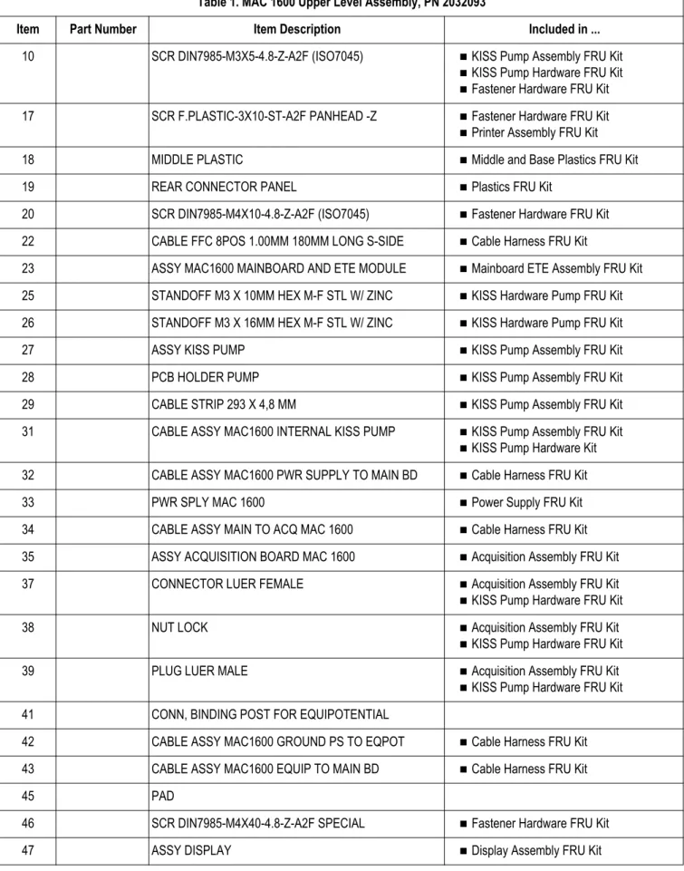
Parts lists . . . 5-1
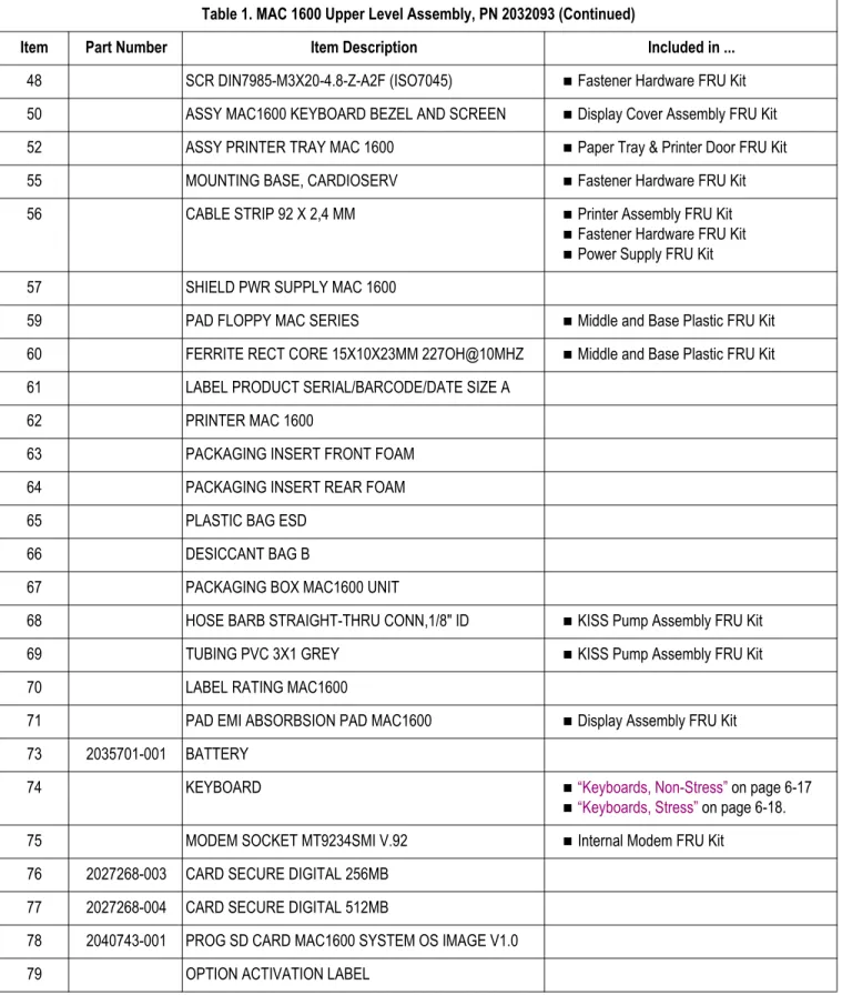
Ordering parts . . . 5-2 General information . . . 5-2 Field replaceable units (FRUs) . . . 5-3 MAC 1600 upper level assembly, PN 2032093 . . . 5-3 Power supply FRU kit, PN 2035703-001 . . . 5-10 Mainboard ETE assembly FRU kit, PN 2035704-001 . . . 5-10 Acquisition assembly FRU kit, PN 2035705-001 . . . 5-10 Cable harness FRU kit, PN 2035707-001 . . . 5-10 Display cover assembly FRU kit, PN 2035706-001 . . . 5-11 Printer assembly FRU kit, PN 2035702-001 . . . 5-11 Paper tray and printer door FRU kit, PN 2035711-001 . . . 5-12 Display assembly FRU kit, PN 2035700-001 . . . 5-12 Printer board assembly FRU kit, PN 2036813-001 . . . 5-12 KISS pump assembly FRU kit, PN 2036814-001 . . . 5-12 KISS pump hardware FRU kit, PN 2036815-001 . . . 5-13 Internal modem FRU kit, PN 2036816-001 . . . 5-13 Printhead FRU kit, PN 2036817-001 . . . 5-13 Optical sensor and bracket FRU kit, PN 2036818-001 . . . 5-13 Fastener hardware FRU kit, PN 2035708-001 . . . 5-14 Middle and base plastic FRU kit, PN 2036812-001 . . . 5-16 Plastics kit, PN 2035709-001 . . . 5-16 Keyboards, non-stress . . . 5-17 Keyboards, stress . . . 5-18 Data Matrix barcode scanner kits . . . 5-19 Power cords . . . 5-20A
Technical specifications . . . A-1
Features & functions . . . A-2 Specifications . . . A-3B
Electromagnetic compatibility . . . B-1
Electromagnetic compatibility (EMC) . . . B-2 Guidance and manufacturer’s declaration - electromagnetic emissions . . . B-2 Guidance and manufacturer’s declaration - electromagnetic immunity . . . . B-4 Guidance and manufacturer's declaration - electromagnetic immunity . . . . B-5 Recommended separation distances . . . B-7 EMC exceptions disclosure . . . B-8C
EMC-compliant supplies & accessories . . . C-1
Introduction . . . C-2 Standard accessories . . . C-3 Value accessories . . . C-4 Thermal papers . . . C-5 Contrast Papers . . . C-5 Premium Papers . . . C-5 Archivist 25 Paper for Europe . . . C-5 Archivist 25 Paper for US . . . C-5 Country-specific power cords . . . C-6 Optional accessories . . . C-7Manual information
Revision history
Each page of the document has the document part number and revision letter at the bottom of the page. The revision letter identifies the document’s update level. The revision history of this document is summarized in the following table.
Table 1. Revision History, PN 2028451-183
Revision Date Comment
A 10 April 2008 Initial release of document.
Manual purpose
This manual supplies technical information for service representatives and technical personnel so they can maintain the equipment to the assembly level. Use it as a guide for maintenance and electrical repairs considered field repairable. Where necessary the manual identifies additional sources of relevant information and/or technical assistance.
See the operator’s manual for the instructions necessary to operate the equipment safely in accordance with its function and intended use.
Intended audience
This manual is intended for the person who uses, maintains, or troubleshoots this equipment.
Warnings, cautions, and notes
The terms danger, warning, and caution are used throughout this manual to point out hazards and to designate a degree or level or seriousness. Familiarize yourself with their definitions and significance.
Hazard is defined as a source of potential injury to a person.
Term Definition
DANGER Indicates an imminent hazard which, if not avoided, will result in death or serious injury.
WARNING Indicates a potential hazard or unsafe practice which, if not avoided, could result in death or serious injury.
CAUTION Indicates a potential hazard or unsafe practice which, if not avoided, could result in minor personal injury or product/property damage.
NOTE Provides application tips or other useful information to assure that you get the most from your equipment.
Safety messages
Additional safety messages may be found throughout this manual that provide appropriate safe operation information.
DANGER
Do not use in the presence of flammable anesthetics.
WARNING
CONNECTION TO MAINS – This is class I equipment. The mains plug must be connected to an appropriately grounded power supply.
WARNING
BATTERY OPERATION – If the integrity of the protective earth conductor is in doubt, operate the unit from its battery.
CAUTIONS
This equipment contains no user serviceable parts. Refer servicing to qualified service personnel.
U.S. Federal law restricts this device to the sale by or on the order of a physician.
Responsibility of the manufacturer
GE is responsible for the effects of safety, reliability, and performance only if:
Assembly operations, extensions, readjustments, modifications, or repairs are
carried out by persons authorized by us.
The electrical installation of the relevant room complies with the requirements of the appropriate regulations.
General
The intended use of this device is to record ECG signals from surface ECG electrodes. This device can analyze, record, and store electrocardiographic information from adult and pediatric populations. This data can then be computer analyzed with various algorithms such as interpretive ECG and signal averaging for presentation to the user.
This device is intended for use under the direct supervision of a licensed health care practitioner.
Failure on the part of the responsible individual, hospital, or institution using this equipment to implement a satisfactory maintenance schedule may cause undue equipment failure and possible health hazards.
To ensure patient safety, use only parts and accessories manufactured or recommended by GE Healthcare.
Contact GE Healthcare for information before connecting any devices to this equipment that are not recommended in this manual.
If the installation of this equipment, in the USA, will use 240 V rather than 120 V, the source must be a center-tapped, 240 V, single-phase circuit.
Parts and accessories used must meet the requirements of the applicable IEC 60601 series safety standards, and/or the system configuration must meet the requirements of the IEC 60601-1-1 medical electrical systems standard.
The use of accessory equipment not complying with the equivalent safety
requirements of this equipment may lead to a reduced level of safety of the resulting system. Consideration relating to the choice shall include:
use of the accessory in the patient vicinity; and
evidence that the safety certification of the accessory has been performed in accordance to the appropriate IEC 60601-1 and/or IEC 60601-1-1 harmonized national standard.
Equipment symbols
See the MAC 1600 operator’s manual for information about the symbols used on this product and its packaging.
Service information
Service requirements
Refer equipment servicing to GE authorized service personnel only. Any unauthorized attempt to repair equipment under warranty voids that warranty. It is the user’s responsibility to report the need for service to GE or to one of their authorized agents.
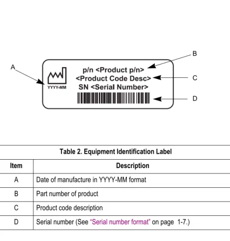
Equipment identification
Label format
B C D ATable 2. Equipment Identification Label
Item Description
A Date of manufacture in YYYY-MM format B Part number of product
C Product code description
D Serial number (See “Serial number format” on page 1-7.)
Serial number format
Every GE device has a unique serial number for identification. The serial number appears on the device label and is formatted as seen in the following illustration. .
# # # # # # # # # # # # #
A B C D E F
A The product code for MAC 1600 systems is SDE. B Year Manufactured (00-99)
08 = 2008 09 = 2009 (and so on)
C Fiscal Week Manufactured D Production Sequence Number E Manufacturing Site
F Miscellaneous Characteristic
The MAC™ 1600 ECG Analysis System is a 12-lead, 12-channel system with a 6.5 inch (165 mm) diagonal display, active patient cable, and battery operation. There are also options for communication capabilities.
Front View
Name Description
A Display Presents waveform and text data.
B Power LED Indicates the unit is plugged in and receiving power. C Battery LED Indicates various battery states:
Solid amber light indicates the battery is charging. Flashing amber light indicates the battery is low. Off indicates the battery is neither charging nor low.
D Keyboard Input device for controlling the system or entering data. See “Keyboard Layout” on page 2-4 for more information. E Writer Prints reports.
Side View
Name Description
A ECG signal input connector
D-sub 15-pin female connector for the acquisition cable.
B KISS Connector Connection port for the optional KISS lead system. C Carrying handle Handle for carrying the MAC 1600 device.
Back View
-Name Description A External Power Connector12V power supply for future external devices. Do not use.
B COMM Port A Serial connector for stress devices (bicycle ergometer or treadmill).
C COMM Port B Serial connector for data communication with CASE/ CardioSoft or MUSE system or connect to an external modem.
WARNING
SYSTEM LEAKAGE CURRENT – Keep leakage current within acceptable limits when connecting auxiliary equipment to this device.
Total system leakage must not exceed 300 microamperes (United States) or 500 microamperes (international).
D Phone jack RJ11 connector from the internal modem to an analog phone line.
E AC power connection Standard connector for the AC power cable. F USB connector Standard Universal Serial Bus connector for USB
devices, such as the optional barcode reader or external USB keyboard.
G LAN connection RJ45 network connector.
H SD card slot Secure Digital card slot. Insert card as indicated by the icon. The MAC 1600 system supports only SD cards formatted for the FAT or FAT16 file systems. I External Video Monitor
connection
Standard 15-pin VGA connector for an external monitor. Connect a medical grade VGA CRT or medical grade VGA compatible LCD display.
NOTE
The MAC 1600 display resolution is 800 by 480 pixels. Due to differing aspect ratios, the image may appear distorted on some LCD monitors. Consult the operating guide for your LCD monitor. J Equipotential grounding
lug
Connect non-grounded peripheral devices to ensure equipotential.
Keyboard
NOTE
The English keyboard is shown in this section.
A B C D E F G I L K J H M N J O Keyboard Name Description A function keys (F1 through F6)
Used to select menu options on the screen.
B Power switch Used to turn the system on, bring the system to Standby mode, or turn the system off. C Leads key Used to change the leads when the screen is being used to display waveforms. D backspace key Used to delete characters.
E ECG key Used to acquire a resting ECG, to print a 10-second report in Arrhythmia mode, or to print a 12-lead report in Stress mode.
F Rhythm key Used to print a continuous, real-time rhythm ECG rhythm strip. Press the Stop key to stop the rhythm strip from printing. (Rhythm report is not stored and cannot be transmitted.)
G Stop key Used to stop the writer from printing.
H Enter key Used to advance the focus in a window or to select items from the screen.
I Trimpad Press arrows to move the cursor left, right, up, or down. Press the center of the Trimpad to move the focus within a window or to select an item.
J shift key Used to enter a capital letter. Press shift + P to type a capital P. K Alt key Used to select menu options in the Windows Explorer.
L space bar Used to add a space between typed characters or to highlight screen items. M option key Used to enter special characters on non-English keyboards.
N Esc key Used to close a window on the screen.
O stress keys These keys will be on your keyboard if your system has the stress option. See “Keyboard (stress option)” on page 2-7 for more information
Keyboard (Continued)
Keyboard (stress option)
NOTE
The English keyboard is shown in this section.
A B C D E F G H I J K L M N O P Name Description
A Pretest key Press to advance to the PRETEST phase (or advance to next stage within the selected phase). B Exercise key Press to advance to the EXERCISE phase (or advance to next stage within the selected phase). C Recovery key Press to advance to the RECOVERY phase (or advance to next stage within the selected phase). D Test end key Press and hold to end the test and start the TEST END phase.
E Hold key Press to maintain the current stage. (Automatic stage sequencing will stop.) Press again to return to stage sequencing.
F Speed W + key Press to manually increase the treadmill belt speed or the ergometer load. G Grade ↑ key Press to increase the elevation of the treadmill belt.
H Start tmill key Press to start the treadmill during the test. I STOP tmill key Press to stop the treadmill during the test.
J Grade ↓ key Press to decrease the elevation of the treadmill belt.
K Speed W - key Press to manually decrease the treadmill belt speed or the ergometer load.
L Enter BP key Press to enter blood pressure readings or to trigger a reading from an external device. M Comment key Press to enter comments about the test. Comments are printed on many of the final reports. N Medians key Press to print a medians report.
O 12ld key Press to print a 12 lead report (10 seconds of acquired data).
Detailed description
Hardware/firmware architecture
The MAC 1600 hardware subsystems include the following:
CPU core Display Keyboard ECG Acquisition Thermal printer Power supply Housing
Power-up self-test
See the MAC 1600 Operator’s Manual, Chapter 2, “Equipment Overview” to verify operation.
On power-up, the system automatically runs an internal self-test. If all tests pass, you will see the start-up screen.
The next screen that appears after the start-up screen depends on the Power up mode
selected in System Configuration. The Resting ECG mode is the default Power up mode.
If the equipment is not working properly, ask yourself the following questions.
Is the unit turned on?
Have there been any changes in the use, location, or environment of the
equipment that could cause the failure?
Has the equipment hardware or software been modified since last use?
Is operator error the cause of the problem?
Try to repeat the scenario exactly and compare that to the proper operation of the equipment described in the manual.
Is the battery installed?
Poor quality ECGs
Poor quality ECGs can be caused by factors in the environment, inadequate patient preparation, hardware failures related to the acquisition module, lead wires, cables, or problems in the unit.
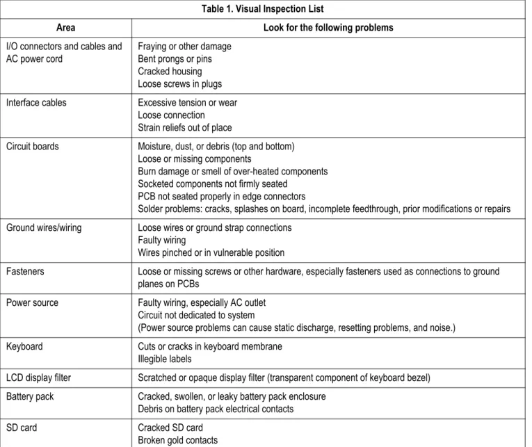
Visual inspection
A thorough visual inspection of the equipment can save time. Small things— disconnected cables, foreign debris on circuit boards, missing hardware, loose components—can frequently cause symptoms and equipment failures that may appear to be unrelated and difficult to track.
NOTE
Take the time to make all the recommended visual checks before starting any detailed troubleshooting procedures.
Table 1. Visual Inspection List
Area Look for the following problems
I/O connectors and cables and AC power cord
Fraying or other damage Bent prongs or pins Cracked housing Loose screws in plugs Interface cables Excessive tension or wear
Loose connection Strain reliefs out of place
Circuit boards Moisture, dust, or debris (top and bottom) Loose or missing components
Burn damage or smell of over-heated components Socketed components not firmly seated
PCB not seated properly in edge connectors
Solder problems: cracks, splashes on board, incomplete feedthrough, prior modifications or repairs Ground wires/wiring Loose wires or ground strap connections
Faulty wiring
Wires pinched or in vulnerable position
Fasteners Loose or missing screws or other hardware, especially fasteners used as connections to ground planes on PCBs
Power source Faulty wiring, especially AC outlet Circuit not dedicated to system
(Power source problems can cause static discharge, resetting problems, and noise.) Keyboard Cuts or cracks in keyboard membrane
Illegible labels
LCD display filter Scratched or opaque display filter (transparent component of keyboard bezel) Battery pack Cracked, swollen, or leaky battery pack enclosure
Debris on battery pack electrical contacts SD card Cracked SD card
Event logging
Setting Up event logging
The MAC 1600 system can be set up to create an Event Log in XML format that contains system errors, warnings, and informational messages. To configure the device for the level of severity of messages written to the Event Log, follow these steps.
1. Power on the MAC 1600 system by pressing the Power button. 2. From the Main Menu, press F5 to select System Configuration. 3. Press F6 to select More.
4. Press F6 to select More again. 5. Press F5 to select Service Setup.
A window opens prompting you to enter the Service password.
6. Type prod and press F6 to select OK. NOTE
If the keyboard does not include the letters prod, type 7763 and press F6 to select OK.
The following window opens.
8. Enable or disable event logging:
Check the Key Event Logging check box to enable writing to the Event Log, or
clear the Key Event Logging check box to disable writing to the Event Log.
9. Select a level of severity to log from the Log Level list:
Select Error to log only errors to the Event Log.
Select Warning to log errors and warnings to the Event Log.
Select Information to log errors, warnings, and information messages to the
Event Log. 10. Press F6 to select Save.
Exporting the event log
1. Repeat steps 1-7 in “Setting Up event logging”.
2. Insert an SD card in SD card slot in back panel as shown in the following figure (with gold contacts up).
3. Press F1 to select Export Log Files.
The current Event Log file, log_0.log, is copied to a log directory on the SD card.
NOTE
The log file can be accessed by inserting the SD card in an SD card reader that is connected to a computer with a Windows operating system and a text editor like Notepad or WordPad. If the Event Log is requested by GE Service for troubleshooting an issue, the file can be sent as an email attachment.
Performing diagnostic tests
Verify that the MAC 1600 resting ECG analysis system operates properly by running the diagnostic tests. These tests check the operation of the display screen, speaker, keyboard, thermal writer, battery, and communications. These diagnostic tests are a useful tools for troubleshooting problems and can be useful as a part of system checkout procedures.
Accessing the system diagnostics function
The System Diagnostics menucan be used to perform functional diagnostic tests. Access the System Diagnostics menu as follows.
1. Power on the MAC 1600 system by pressing the Power button. 2. From the Main Menu, press F5 to select System Configuration. 3. Press F6 to select More.
4. Press F6 to select More again. 5. Press F5 to select Service Setup.
A window opens prompting you to enter the Service password.
6. Type prod and press F6 to select OK. NOTE
If the keyboard does not include the letters prod, type 7763 and press F6 to select OK.
The following window opens.
7. Move the focus to the System Diagnostics button and press the Enter key to select.
The DIAGNOSTIC TESTS window opens.
The following sections describe how to perform the specific diagnostic tests. Proceed to the appropriate section for the test you need to perform.
Testing the display
The Display Test can be used to determine if the display pixels are working properly.
1. Open the DIAGNOSTIC TESTS window as described in “Accessing the system diagnostics function” on page 3-6.
3. Select the Start Test button. The following window opens.
4. Press the right arrow key on the Trimpad repeatedly to move the color bars horizontally across the screen.
right arrow key
5. Verify that the color band pattern (red, green, blue, white) scrolls across the screen. Pass the test if the pattern is replicated without discoloration. 6. Press the F1 key to switch to horizontal color bars.
7. Press the down arrow key repeatedly. Verify that the color band pattern (red, green, blue, white) scrolls down the screen. Pass the test if the pattern is replicated without discoloration.
8. Press the F1 key to switch to cycle through the solid color pane (red, green, blue, white). For each pane, check for black pixels. Pass the test if no more than 4 black pixels are observed on any single color pane. Note that a black pixel observed on one pane will probably be observed on every pane. 9. Press Esc or return when the test is complete.
The following window opens.
10. Select pass or fail:
If the test passed, press F4 to select Yes.
If the test failed, press F5 to select No.
11. If the display test failed, replace the display assembly as described in
Testing the speaker
The Speaker Test can be used to determine if the speaker is working properly. 1. Open the DIAGNOSTIC TESTS window as described in “Accessing the system
diagnostics function” on page 3-6. 2. Select the Speaker Test button.
3. Listen for a brief audible tone coming from the speaker. The following window opens.
4. Select pass or fail:
If you heard an audible tone, press F4 to select Yes.
If you did not hear an audible tone, press F5 to select No.
5. If the speaker test failed, replace the mainboard/ETE module assembly as described in “Replacing the mainboard/ETE module assembly” beginning on page 4-33.
Testing the keyboard
The Keyboard Test can be used to determine if the keyboard is working properly. 1. Open the DIAGNOSTIC TESTS window as described in “Accessing the system
diagnostics function” on page 3-6. 2. Select the Keyboard Test button.
3. Press each key on the keyboard and verify that an asterisk (*) appears in the corresponding representation of that key on the screen.
A key passes the test if an asterisk appears on the screen when the corresponding key is pressed.
4. To test for “sticky keys”, continue to press keys that already have asterisk on the screen and verify that the screen representation of the key is highlighted with each subsequent key press.
A key passes if the key on the screen highlights with each repeated key press. 5. When the test is complete, press the Shift + F6 keys.
The following window opens.
6. Select pass or fail:
If every key passes the tests in steps 3 and 4, press F4 to select Yes. If any key fails the tests in steps 3 or 4, press F5 to select No.
7. If the keyboard test failed, replace the keyboard assembly as described in
Testing the acquisition module
The Acquisition Module Test can be used to determine if the acquisition board is working properly.
1. Open the DIAGNOSTIC TESTS window as described in “Accessing the system diagnostics function” on page 3-6.
2. Select the Acquisition Module Test button.
A window similar to the one shown in the following figure opens.
Passed 1 1
3. Note the test result and press F6 to select Cancel. 4. If the result of the Acquisition Module Test was Failed:
a. Re-seat or double-check acquisition board harnesses and repeat the acquisition module test.
b. If the test still fails after re-seating the board and checking the harnesses, replace acquisition board as described in “Replacing the acquisition board assembly” beginning on page 4-15.
c. Repeat the acquisition module test after replacing the board to verify functionality.
d. If the test still fails after replacing the acquisition board, replace the mainboard/ETE module as described in “Replacing the mainboard/ETE module assembly” beginning on page 4-33.
Checking battery status
The Battery Test can be used to determine the status of the Lithium-Ion battery. This test must be performed while running on battery power.
1. Disconnect the device from AC power and wait at least one minute.
2. Open the DIAGNOSTIC TESTS window as described in “Accessing the system diagnostics function” on page 3-6.
3. Select the Battery Test button.
A window similar to the one shown in the following figure opens.
AC Line Status: Battery Life Remaining (hh:mm) Battery Charge Remaining [%]
AC Power Line OFF 2:08
50
NOTE
Battery Life Remaining is the estimated time remaining based on the present current draw. Because no printing is occurring during this status check, this time is calculated based on using the system for display purposes only. Actual remaining battery life will be less when the system is used for both display and printing purposes.
Battery Charge Remaining can range from 0 to 100%.
According to the battery specifications (see “Specifications” on page A-3), you should see at least 3:00 (three hours) of Battery Life Remaining
(display time) with 100% Battery Charge Remaining. If the numbers displayed in this window are less, you may require more frequent battery charging or you may wish to replace the battery. See “Replacing the battery” on page 4-7 for information on how to replace the battery. 4. Note the battery status information and press F6 to select Cancel and close the
BATTERY STATUS window.
Testing the writer
The Writer Test can be used to determine if the writer is working properly. NOTE
Before performing the Writer Test, be sure that thermal paper is properly loaded in the writer tray.
1. Open the DIAGNOSTIC TESTS window as described in “Accessing the system diagnostics function” on page 3-6.
The following window opens.
3. Perform the 50mm/s Speed Test.
a. Select the 50mm/s Speed Test button.
The writer prints the 50 mm/s speed test report.
b. When one page of the report has printed, press the Stop button. The following window opens.
c. Examine the printed report. Use the following criteria to determine if the writer passed or failed the 50mm/s speed test.
If one cycle of the square wave spans 50 mm on paper, measured from
corner to corner of wave, with allowable tolerance of 1.0 mm, the test passes.
If the above criteria is not met, the test fails. d. If the test passed, press F4 to select Yes.
If the test failed, press F5 to select No.
4. Repeat the previous step for the other speed tests. The pass-fail criteria for each of the remaining tests are as follows:
25mm/s Speed Test - If one cycle of the square wave spans 25 mm on paper, measured from corner to corner of wave, with allowable tolerance of 0.5 mm (2%), the test passes. If this criteria is not met, the test fails.
12.5mm/s Speed Test - Measure five or more cycles and divide your
measurement by the number of cycles measured. If one cycle of the square wave spans 12.5 mm on paper, measured from corner to corner of wave, with allowable tolerance of 0.5 +1.25 mm (10%), the test passes. If this criteria is not met, the test fails.
5mm/s Speed Test - Measure five or more cycles and divide your measurement by the number of cycles measured. If one cycle of the square wave spans 5 mm on paper, measured from corner to corner of wave, with allowable tolerance of 0.25 +0.5 mm (10%), the test passes. If this criteria is not met, the test fails.
a. Select the Print Head Test button.
The writer prints a 1-page print head test report.
b. Verify that there are no gaps in any of the lines printed. Up to 5 mm of blank paper is allowable at the top and bottom of the page.
The following window opens.
c. If there are no gaps in the lines on the printed report, press F4 to select Yes. If there are gaps in the lines on the printed report, press F5 to select No. 6. When all writer tests have been performed, press F6 to select Cancel and close
the window.
7. If one or more of the writer tests fail, use the following table to determine how to proceed.
Observed Failure Remedy
Improper paper queuing Replace queue sensors.
See “Replacing queue hole sensor” on page 4-30. See “Replacing queue mark sensor” on page 4-32.
Missing dots
(gaps in printed report)
Replace the printhead.
See “Replacing the printhead” on page 4-26.
Faded prints Faulty roller. Replace paper tray assembly.
1. Roller included with paper tray assembly.
1
See “Replacing the paper tray assembly” on page 4-6.
Printhead pressure problem
Replace springs.
Incorrect print speed Faulty stepper motor. Replace paper tray assembly.
2. Stepper motor included with paper tray assembly.
2
See “Replacing the paper tray assembly” on page 4-6.
Replace printer board.
See “Replacing the printer board” on page 4-24.
Writer paper does not
move Faulty stepper motor. Replace paper tray assembly.
3. Stepper motor included with paper tray assembly.
3
See “Replacing the paper tray assembly” on page 4-6.
Replace the printer assembly.
See “Replacing the printer assembly” on page 4-19.
Paper moves but lines do not print
Faulty cables in printer assembly.
See “Replacing the printer assembly” on page 4-19.
Replace the printhead.
Testing the RS232 port
The RS232 Test can be used to determine if the Com ports are working properly. 1. Open the DIAGNOSTIC TESTS window as described in “Accessing the system
diagnostics function” on page 3-6.
2. Use a paper clip to short pins 2 & 3 on COM A.
5 4 3 2 1
9 8 7 6
3. Select the RS232 Test button. The following window opens.
4. Perform the COM Port loop back test on COM 1. a. With the focus on COM 1, press the Enter key.
The results of the COM 1 loop back test are displayed. b. Note the results of the COM 1 loop back test.
5. Perform the COM Port loop back test on COM 2.
a. Use the paper clip to short pins 2 & 3 on the COM B connector. b. With the focus on COM 2, press the Enter key.
The results of the COM 2 loop back test are displayed. c. Note the results of the COM 2 loop back test.
6. Press Esc or F6 (Cancel) when the test is complete.
7. If either test failed, replace the mainboard/ETE module as described in
Testing the LAN option
The LAN Test can be used to test network connectivity. 1. Connect the MAC 1600 device to an active LAN.
NOTE
Ensure that the LAN is an active network. If you connect to an inactive network tap, the test result may be a false negative.
2. Open the DIAGNOSTIC TESTS window as described in “Accessing the system diagnostics function” on page 3-6.
3. Select the LAN Test button. The following window opens.
4. Press the Enter key to select the Test network connectivity button. The Checking connectivity. Please wait. message is displayed. Then, the test results are displayed.
If the System Connected to Network message is displayed in the window, the test passes.
If the Network Unavailable message is displayed in the window and you
are sure the device is connected to an active network, the test fails. 5. Press Esc or F6 (Cancel) after the test results are displayed.
6. If the test failed, replace the mainboard/ETE module as described in “Replacing the mainboard/ETE module assembly” beginning on page 4-33.
Testing the modem
The Modem Test can be used to test the internal and the external modem. 1. Connect the MAC 1600 device to an active analog phone line.
NOTE
Ensure that the phone line is active. If you connect to an inactive phone line, the test result may be a false negative.
2. Open the DIAGNOSTIC TESTS window as described in “Accessing the system diagnostics function” on page 3-6.
3. Select the Modem Test button. The following window opens.
4. Test the internal modem as described in the following steps.
a. With the focus on the Internal Modem Test button, press the Enter key. The Test in Progress. Please wait message is displayed.
Then the results of the test are displayed.
If the Passed message is displayed in the window, the test passes. If the Failed message is displayed in the window, the test fails. b. If the system has an external modem, go to step 5. If the system has only
the internal modem option, press F6 to select Cancel. Then, go to step 6. 5. Test the external modem as described in the following steps.
a. With the focus on the External Modem Test button, press the Enter key. The Test in Progress. Please wait message is displayed.
Then the results of the test are displayed.
If the Passed message is displayed in the window, the test passes.
If the Failed message is displayed in the window, the test fails.
b. Press Esc or F6 (Cancel) when the test is complete.
6. If the Internal Modem Test failed, replace the internal modem as described in
“Replacing the internal modem (option)” on page 4-12. 7. If the External Modem Test failed, replace the external modem.
Testing the USB port
The USB Test can be used to test the USB port.
1. Open the DIAGNOSTIC TESTS window as described in “Accessing the system diagnostics function” on page 3-6.
2. Connect a USB keyboard to the USB port of the MAC 1600 back panel. NOTE
The USB keyboard used for this test must match the language that is selected in setup.
3. Select the USB Test button. The following window opens.
4. Press any key on the USB keyboard and verify pass or fail:
If the character that appears in the Character Input field matches the key
you pressed, the test is passed.
If the character does not match or no character appears in the Character
Input field, the test fails.
5. Press Esc or F6 (Cancel) when the test is complete. The following window opens.
6. Press F4 to select Yes if the test passed or press F5 to select No if the test failed. 7. If the test fails, replace the mainboard/ETE module as described in “Replacing
Testing the patient lead wires
Test the patient leadwires as described in this section.
1. Open the DIAGNOSTIC TESTS window as described in “Accessing the system diagnostics function” on page 3-6.
2. Connect a patient cable with lead wires to the MAC 1600 patient cable connector.
3. Connect all leads to a patient simulator or shorting bar. 4. Select the Patient Lead Wire Check button.
The following window opens.
5. Press the Enter key to select the Start Test button. For each lead wire, the test results are displayed.
If the Connected message is displayed, the lead wire passes the test. If the Disconnected message is displayed, the lead wire fails the test. 6. Press Esc or F6 (Cancel) when the test is complete.
7. Replace every lead wire that failed the test. 8. Repeat the test.
If the lead wire still fails the test, replace the acquisition board as described in
Equipment problems
ECG data noise
If the acquired ECG data displays unacceptable noise levels:
When troubleshooting noise or signal quality, be sure the problem is not being caused by poor skin preparation, or placement and condition of electrodes. Careful skin preparation is the key to an interference-free ECG. Signal quality is indicated using Hookup Advisor. Hookup Advisor can be turned on or off in the ECG menu. Select System Setup>ECG>ECG Acquisition.
Check for defective or date-expired electrodes.
Check for defective, broken, or disconnected leadwires.
Run the “Testing the acquisition module” on page 3-11 to ensure that all lead
Error codes
No action is necessary for isolated error occurrences. However, if the unit is malfunctioning and any of the following error messages are repeating and unrecoverable, replace the FRUs in the order as listed.
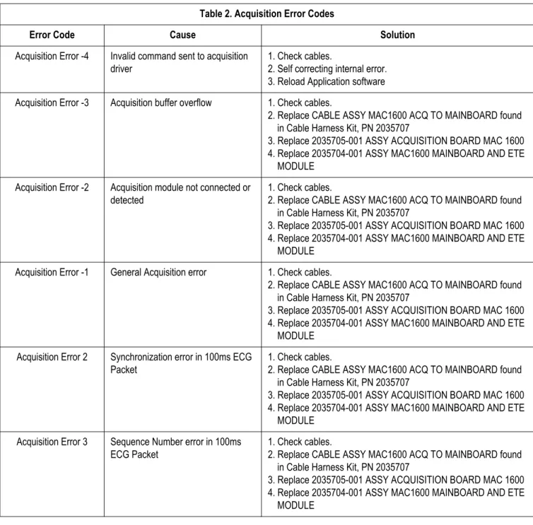
Acquisition error codes
Where multiple solutions are suggested, perform the suggested actions in their listed order. Once a solution restores functionality, do not attempt the next solution in the list.
Table 2. Acquisition Error Codes
Error Code Cause Solution
Acquisition Error -4 Invalid command sent to acquisition driver
1. Check cables.
2. Self correcting internal error. 3. Reload Application software Acquisition Error -3 Acquisition buffer overflow 1. Check cables.
2. Replace CABLE ASSY MAC1600 ACQ TO MAINBOARD found in Cable Harness Kit, PN 2035707
3. Replace 2035705-001 ASSY ACQUISITION BOARD MAC 1600 4. Replace 2035704-001 ASSY MAC1600 MAINBOARD AND ETE
MODULE Acquisition Error -2 Acquisition module not connected or
detected
1. Check cables.
2. Replace CABLE ASSY MAC1600 ACQ TO MAINBOARD found in Cable Harness Kit, PN 2035707
3. Replace 2035705-001 ASSY ACQUISITION BOARD MAC 1600 4. Replace 2035704-001 ASSY MAC1600 MAINBOARD AND ETE
MODULE Acquisition Error -1 General Acquisition error 1. Check cables.
2. Replace CABLE ASSY MAC1600 ACQ TO MAINBOARD found in Cable Harness Kit, PN 2035707
3. Replace 2035705-001 ASSY ACQUISITION BOARD MAC 1600 4. Replace 2035704-001 ASSY MAC1600 MAINBOARD AND ETE
MODULE Acquisition Error 2 Synchronization error in 100ms ECG
Packet
1. Check cables.
2. Replace CABLE ASSY MAC1600 ACQ TO MAINBOARD found in Cable Harness Kit, PN 2035707
3. Replace 2035705-001 ASSY ACQUISITION BOARD MAC 1600 4. Replace 2035704-001 ASSY MAC1600 MAINBOARD AND ETE
MODULE Acquisition Error 3 Sequence Number error in 100ms
ECG Packet
1. Check cables.
2. Replace CABLE ASSY MAC1600 ACQ TO MAINBOARD found in Cable Harness Kit, PN 2035707
3. Replace 2035705-001 ASSY ACQUISITION BOARD MAC 1600 4. Replace 2035704-001 ASSY MAC1600 MAINBOARD AND ETE
Acquisition Error 4 Checksum error in 100ms ECG Packet
1. Check cables.
2. Replace CABLE ASSY MAC1600 ACQ TO MAINBOARD found in Cable Harness Kit, PN 2035707
3. Replace 2035705-001 ASSY ACQUISITION BOARD MAC 1600 4. Replace 2035704-001 ASSY MAC1600 MAINBOARD AND ETE
MODULE Acquisition Error 7 Acquisition self test error 1. Check cables.
2. Replace 2035705-001 ASSY ACQUISITION BOARD MAC 1600 Acquisition Error 8 Error loading the acquisition firmware 1. Reload application software
2. Replace CABLE ASSY MAC1600 ACQ TO MAINBOARD found in Cable Harness Kit, PN 2035707
3. Replace 2035705-001 ASSY ACQUISITION BOARD MAC 1600 4. Replace 2035704-001 ASSY MAC1600 MAINBOARD AND ETE
MODULE
Acquisition Error 9 Acquisition driver failed to open 1. Replace CABLE ASSY MAC1600 ACQ TO MAINBOARD found in Cable Harness Kit, PN 2035707
2. Replace 2035705-001 ASSY ACQUISITION BOARD MAC 1600 3. Replace 2035704-001 ASSY MAC1600 MAINBOARD AND ETE
MODULE Acquisition Error 10 Acquisition driver communication
error
1. Replace CABLE ASSY MAC1600 ACQ TO MAINBOARD found in Cable Harness Kit, PN 2035707
2. Replace 2035705-001 ASSY ACQUISITION BOARD MAC 1600 3. Replace 2035704-001 ASSY MAC1600 MAINBOARD AND ETE
MODULE
Acquisition Error 11 Acquisition firmware file not found 1. Reload application software Table 2. Acquisition Error Codes (Continued)
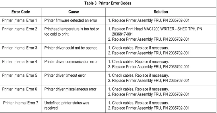
Printer error codes
Table 3. Printer Error Codes
Error Code Cause Solution
Printer Internal Error 1 Printer firmware detected an error 1. Replace Printer Assembly FRU, PN 2035702-001 Printer Internal Error 2 Printhead temperature is too hot or
too cold to print
1. Replace Print Head MAC1200 WRITER - SHEC TPH, PN 2036817-001
2. Replace Printer Assembly FRU, PN 2035702-001 Printer Internal Error 3 Printer driver could not be opened 1. Check cables. Replace if necessary.
2. Replace Printer Assembly FRU, PN 2035702-001 Printer Internal Error 4 Printer driver communication error 1. Check cables. Replace if necessary.
2. Replace Printer Assembly FRU, PN 2035702-001 Printer Internal Error 5 Printer driver timeout error 1. Check cables. Replace if necessary.
2. Replace Printer Assembly FRU, PN 2035702-001 Printer Internal Error 6 Printer driver miscellaneous error 1. Check cables. Replace if necessary.
2. Replace Printer Assembly FRU, PN 2035702-001 Printer Internal Error 7 Undefined printer status was
received
1. Check cables. Replace if necessary.
Frequently asked questions
Maintenance
NOTE
See the MAC 1600 Operator’s Manual for complete System Configuration
information.
Saving system setups to SD card
Q: How do I save changes I have made to the System Configuration? A: Perform the following steps:
1. Insert an SD card in SD card slot in back panel as shown in the following figure (with gold contacts up).
2. Push the SD card into slot to seat it in place.
3. From the Main Menu, press F5 to select System Configuration. 4. Press F6 to select More.
5. Press F6 again to select More. 6. Press F3 to select Export Setup.
Select Setup for Export. Loaded Setup
Setup files in internal storage Setup files on external media
>> Setup1
Setup2
7. Highlight the setup file you want to save to SD card from the list on left side of the window.
8. Press F1 to select Export.
9. The Configuration was successfully exported window opens. 10. Press F6 to select OK.
Q: How do I restore system setups from the SD card? A: Perform the following steps:
1. Insert the SD card in the SD card slot in the back panel as described previously.
2. From the Main Menu, press F5 to select System Configuration. 3. Press F6 to select More.
4. Press F6 again to select More. 5. Press F2 to select Import Setup.
6. Highlight the setup file you want to import from the SD card from the list on right side of the window.
7. Press F1 to select Import.
8. The Configuration was successfully imported window opens. 9. Press F6 to select OK.
10. Eject the SD card by pushing it in once. Store it to a secure location.
Printing a system setup report
Q: I would also like a printed record of my MAC 1600 System Configuration file. How do I obtain this report?
A: Perform the following steps:
1. From the Main Menu, press F5 to select System Configuration. 2. Press F6 to select More.
3. Press F3 to select Print Setup Report.
4. Move the focus to the Complete Setup button and press the Enter key to select.
5. Save the printed setup report in a secure location. It can be used as a reference if the system setup needs to be restored manually.
Option codes
Q: I need to re-activate the options on my MAC 1600 device. Where can I find the option codes?
A: The option codes for the MAC 1600 device are not part of System
Configuration settings. However, these codes will be listed on the last page of your printed setup report. These codes are also found on a label next to the battery compartment. The printed list of option codes is a more convenient aid to use when these codes need to be re-entered after the new mainboard is installed.
Storing ECGs
Q: Why won't any of the ECGs I perform save to the SD card? A: Check the following:
Check that the SD card is fully inserted into the drive. Make sure you are using 256 MB or 512 MB SD cards.
Verify that the SD card is not write-protected. Try a new SD card.
If your system is not set up to automatically save records, you must
manually save by pressing Store.
Cleaning
Q: Should I clean the MAC 1600?
A: Clean the exterior surfaces of all the equipment and peripheral devices monthly, or more frequently if needed.
Use a clean, soft cloth and a mild dishwashing detergent diluted in water.
Wring the excess water from the cloth. Do NOT drip water or any liquid on
the writer assembly, and avoid contact with open vents, plugs, and connectors.
Dry the surfaces with a clean cloth or paper towel.
Battery capacity
Q: What is the capacity of the battery?
A: GE recommend that the MAC 1600 be connected to AC power through a wall outlet whenever it is not in use. However, if operating the device off AC power, be aware that a fully-charged battery is capable of taking approximately 50 or more ECGs with one-page printed reports or three hours of continuous operation (without printing).
MAC address
Q: I need to provide the MAC address of the device to the network administrator to enable the LAN communication option. How do I obtain the MAC address? A: Follow these steps to obtain the MAC address:
1. Open the DIAGNOSTIC TESTS window as described in “Accessing the system diagnostics function” on page 3-6.
2. Move the focus to the Service Report button and press the Enter key to select.
System setup
Location number
Q: When entering in the patient data, how do I get the Location field to automatically populate with the same number?
A: The Location number can be set in Basic Setup to save you from entering it for each test.
1. From the Main Menu, press F5 to select System Configuration. 2. Press F1 to select Basic Setup.
3. Move the focus to the Location field. 4. Type the desired Location number. 5. Press F6 to select Save.
6. Press F5 to select Main Menu.
Patient questions
Q: How do I change what questions I see when I am entering the patient data? A: The patient questions you see on the Patient Data window when starting a test
were set up in Patient Setup.
1. From the Main Menu, press F5 to select System Configuration. 2. Press F6 to select More.
3. Press F4 to select Patient Setup. 4. Press F4 to select Page Down.
5. Move the focus to the Extra Questions... button and press the Enter key to select.
6. The Extra Questions window opens.
7. For each extra question you wish to ask in the Patient Data window, type the Prompt and select the type of question from the Type list
(Alphanumeric, Numeric, Yes/No/Unknown).
8. Press F6 to select Save in the Extra Questions window. 9. Press F6 to select Save in the Test Information Setup window. 10. Return to the Main Menu.
Passwords
Q: The system was setup for High Security Mode and I forgot my password. How do I access the system?
A: Follow these steps to access the system.
1. Contact GE Tech Support and provide the serial number of the device you want to access.
GE Tech Support will generate a temporary, device-specific name and password that can only be used for 24 hours.
2. Log into the system with the user ID MACService and the password provided by GE Tech Support.
NOTE
If the keyboard on the unit does not include the letters for the MACService user ID, type 6227378423 for the user ID.
3. Immediately after logging into the system, verify your MAC 1600 user name and password. Record this information and store in a secure location for future reference.
Clinical
Resting ECG report format
Q: How do I change the way an ECG looks (format) when it prints out? A: Follow these steps to change the ECG format.
1. From the Main Menu, press F5 to select System Configuration. 2. Press F2 to select Resting ECG.
3. Press F4 twice to select Page Down twice. 4. Select a Lead Sequence and Rhythm Leads. 5. Press F6 to select Save.
Editing
Q: Can you edit the interpretation at the MAC 1600 device, and then transmit the edited record to the MUSE system as an unconfirmed record?
A: If you edit demographic information only the record is still transmitted to the MUSE system as an unconfirmed record. However, if you edit the
interpretation, the data will not be saved unless the record is confirmed at the MAC 1600 system. The record is transmitted to the MUSE system as a confirmed record as well.
Navigating the user interface
Q: How do I navigate from the startup screen to the Main Menu?
A: The MAC 1600 system can be configured in a number of different ways. Some of these configuration choices determine the actions that need to be performed in order to proceed from the power up display to the Main Menu. There are three configurations that determine the initial window that appears at power up and what actions the user will need to perform to navigate to the Main Menu.
Power up mode currently selected in Basic Setup:
High Security Mode enabled in Basic Setup:
USB Barcode Reader support option activated - yes or no.
The various steps in this section describe how to navigate from the power up screen to the Main Menu for the various system configurations. Use the steps that apply to your system configuration settings.
If your system is configured to power up in the Resting ECG mode, go to “Resting ECG power up mode” on page 3-30.
If your system is configured to power up in the Arrhythmia mode,
go to “Arrhythmia power up mode” on page 3-30.
If your system is configured to power up in the Main Screen mode, go to “Main Screen Power Up Mode” on page 3-31
If your system is configured to power up in the Stress ECG mode,
Resting ECG power up mode
These steps describe how to navigate to the Main Menu after powering on the MAC 1600 system when Resting ECG is selected for Power up mode in Basic Setup. 1. If the High Security Mode is enabled, proceed with steps a-d after the window
opens prompting for a User ID and Password. If the password prompt does not appear, go to step 2.
NOTE
If you need to perform system setup functions, be sure you log in as a user that is assigned setup editing privileges.
a. Type your user ID in the User ID field.
b. Press the Enter key or press the down arrow key on the Trimpad to move the focus to the Password field.
c. Type your password in the Password field. d. Press the F5 key to select Login.
2. Press F5 to select Cancel. 3. Press F6 to select More. 4. Press F5 to select Main Menu.
Arrhythmia power up mode
These steps describe how to navigate to the Main Menu after powering on the MAC 1600 system when Arrhythmia is selected for Power up mode in Basic Setup. 1. If the High Security Mode is enabled, proceed with steps a-d after the window
opens prompting for a User ID and Password. If the password prompt does not appear, go to step 2.
NOTE
If you need to perform system setup functions, be sure you log in as a user that is assigned setup editing privileges.
a. Type your user ID in the User ID field.
b. Press the Enter key or press the down arrow key on the Trimpad to move the focus to the Password field.
c. Type your password in the Password field. d. Press the F5 key to select Login.
If the barcode reader option is enabled, a window opens prompting you to Scan the Patient barcode.
2. Press F6 to select Cancel. NOTE
If the barcode prompt does not appear, go to step 3. 3. Press F5 to select Cancel.
4. Press F6 to select More. 5. Press F5 to select Main Menu.
Main Screen Power Up Mode
These steps describe how to navigate to the Main Menu after powering on the MAC 1600 system when Main Screen is selected for Power up mode in Basic Setup. 1. If the High Security Mode is enabled, proceed with steps a-d after the window
opens prompting for a User ID and Password. If the password prompt does not appear, go to step 2.
NOTE
If you need to perform system setup functions, be sure you log in as a user that is assigned setup editing privileges.
a. Type your user ID in the User ID field.
b. Press the Enter key or press the down arrow key on the Trimpad to move the focus to the Password field.
c. Type your password in the Password field. d. Press the F5 key to select Login.
The Main Menu is displayed.
2. If the system is configured for Main Screen Power up mode and does not have the High Security Mode enabled, the Main Menu appears after powering up the system. No further keys need to be pressed in order to display the Main Menu.
Stress ECG power up mode
These steps describe how to navigate to the Main Menu after powering on the MAC 1600 system when Stress ECG is selected for Power up mode in Basic Setup. 1. If the High Security Mode is enabled, proceed with steps a-d after the window opens prompting for a User ID and Password. If the password prompt does not appear, go to step 2.
NOTE
If you need to perform system setup functions, be sure you log in as a user that is assigned setup editing privileges.
a. Type your user ID in the User ID field.
b. Press the Enter key or press the down arrow key on the Trimpad to move the focus to the Password field.
c. Type your password in the Password field. d. Press the F5 key to select Login.
If the barcode reader option is enabled, a window opens prompting you to Scan the Patient barcode.
2. Press F6 to select Cancel. NOTE
If the barcode prompt does not appear, go to step 3. 3. Press F5 to select Cancel.
4. Press F6 to select More. 5. Press F6 to select More. 6. Press F5 to select Main Menu.
Introduction
Recommended maintenance
Regular maintenance, irrespective of usage, is essential to ensure that the equipment will always be functional when required.
See the MAC 1600 operator’s manual for cleaning procedures. The MAC 1600 system does not require any calibration procedures. GE recommends that electrical safety checks be performed annually.
WARNING
Failure on the part of all responsible individuals, hospitals or institutions, employing the use of this device, to implement the recommended maintenance schedule may cause equipment failure and possible health hazards. The manufacturer does not in any manner, assume the responsibility for performing the
recommended maintenance schedule, unless an Equipment Maintenance Agreement exists. The sole responsibility rests with the individuals, hospitals, or institutions utilizing the device.
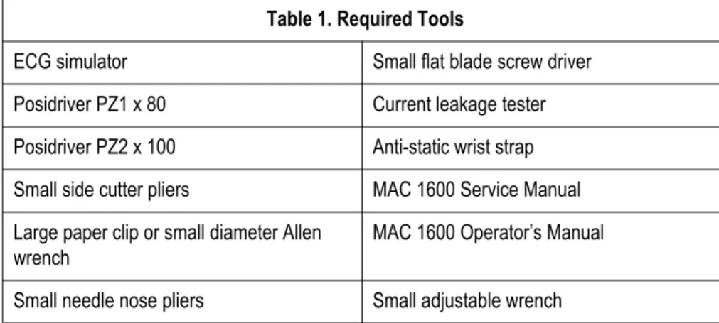
Required tools and supplies
The following table lists the tools required to perform the procedures described in this chapter.
Table 1. Required Tools
ECG simulator Small flat blade screw driver Posidriver PZ1 x 80 Current leakage tester Posidriver PZ2 x 100 Anti-static wrist strap Small side cutter pliers MAC 1600 Service Manual Large paper clip or small diameter Allen
wrench
MAC 1600 Operator’s Manual Small needle nose pliers Small adjustable wrench
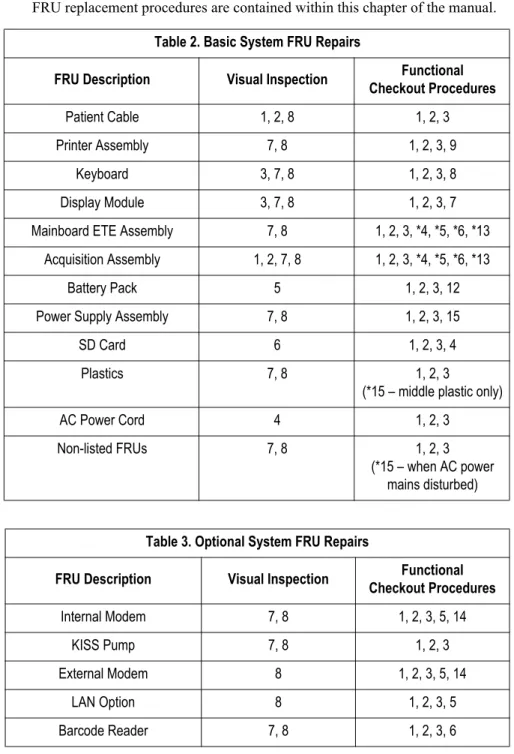
FRU replacement procedures
High level FRU identification
A B M N G D C E F J K L H I Item Description A paper tray assembly B internal modem (option) C display
D keyboard E battery
F barcode reader (option) G patient cable
H base plastic assembly I middle plastic assembly J KISS pump (option) Item Description
K mainboard ETE assembly L power supply assembly M printer assembly
N acquisition module assembly Item Description
Preparing system for FRU replacement
Prior to performing any disassembly procedures, perform these steps. NOTE
Take strict precautions against electrostatic discharge damage while replacing field replaceable units.
1. Power off the system
2. Disconnect the unit from the AC wall outlet.
3. Disconnect the power cord from the back panel connector.
4. Disconnect the patient cable from the unit as described in “Replacing the patient cable” on page 4-4.
5. Remove the paper tray assembly as described in “Replacing the paper tray assembly” on page 4-6.
6. Remove the battery as described in “Replacing the battery” on page 4-7.
Replacing the patient cable
1. Disconnect the system from AC power.
2. Disconnect the patient cable from the MAC 1600 side panel connector as shown in the following figure.
3. Connect a new patient cable to side panel connector. 4. Perform the applicable checkout procedures.
Replacing barcode reader or barcode reader cable
1. Power off the system and disconnect from AC power.
2. Disconnect the barcode reader from the USB connector on the MAC 1600 back panel as shown in the following figure.
3. If only the cable is to be replaced, disconnect the cable from the barcode reader as shown in the following figure.
a. Insert an Allen wrench (or straightened paper clip) in the small hole in the base of the barcode reader.
b. While pushing the tool into the hole, pull the cable to remove it from the base of the barcode reader.
4. Reverse the disassembly procedures to reassemble using a new . Insert USB connector with (the USB symbol) facing down.
5. Configure the new barcode reader as described in the MAC 1600 Operator’s Manual.
6. Perform the applicable checkout procedures. Refer to “Functional checkout” on page 4-38.
Replacing the paper tray assembly
1. Disconnect the system from AC power.
2. Press down on the paper tray release button and pull up on the roller holder.
3. Pull the paper tray until it stops.
4. Press and hold the release tab (A) on the base plastic. Then pull the paper tray to remove it completely from the device.
A
5. Reassemble the paper tray assembly by reversing the steps for removal. 6. Perform the applicable checkout procedures.
Replacing the battery
1. Disconnect the system from AC power.
2. Remove the paper tray assembly as described in “Replacing the paper tray assembly” on page 4-6.
3. Turn the unit over.
4. Press the battery release tab (A) and raise the battery from its compartment to remove it.
A
WARNING
BATTERY PACK DISPOSAL – Do NOT dispose of the battery by fire or burning.
Follow local environmental guidelines concerning disposal and recycling.
5. Insert new battery by reversing the steps for removal. 6. Connect to AC power and power on the system. 7. Perform the applicable checkout procedures.
Replacing the keyboard
1. Disconnect the system from AC power.
2. Remove the paper tray as described in “Replacing the paper tray assembly”. 3. Remove the battery as described in “Replacing the battery”.
4. Remove the two screws (A) from the bottom of the device.
A
5. Turn unit over right side up.
6. Push a small Allen wrench (or straightened paper clip) into one of the keyboard bezel release holes (A) as shown in the following figure while pushing up on the corner of the keyboard bezel (B).
B
7. Repeat step 6 for the other corner of the keyboard bezel.
The two keyboard bezel release holes (A) are shown in the following figure.
A
8. Lift the back end of the keyboard bezel approximately one inch.
9. Push forward on the bezel, in the direction indicated by arrow in the following figure, to unlatch its tabs from the four alignment holes at the front of keyboard bezel from the unit.
10. Remove the keyboard bezel. 11. Lift the keyboard.
12. On the back side of the keyboard, pull down on the lock-release tabs (A) on each side of the keyboard cable connector shown in the following figure.
13. Disconnect the keyboard cable as shown.
14. Remove the keyboard.
15. Reassemble a new keyboard by reversing the steps for removal.
The following sequence of steps describes how to replace the keyboard bezel: a. Align the four tabs (A) at the front of the keyboard bezel with the
four holes in the middle plastic.
A
b. Firmly push the keyboard bezel tabs into the holes.
c. Push down on each corner at the rear of the keyboard bezel until it snaps into position.
16. Perform the applicable checkout procedures. Refer to “Functional checkout” on page 4-38.
Replacing the display assembly
1. Disconnect the system from AC power.
2. Remove the paper tray as described in “Replacing the paper tray assembly”. 3. Remove the battery as described in “Replacing the battery”.
4. Remove the keyboard bezel as described in “Replacing the keyboard” on page 4-8.
5. Remove the four screws (A) that hold the display assembly in place.
A
6. Lift the display out of the assembly.
7. Reassemble the display by reversing the steps for removal. 8. Perform the applicable checkout procedures.
Replacing the internal modem (option)
1. Disconnect the system from AC power.
2. Remove the paper tray as described in “Replacing the paper tray assembly”. 3. Remove the battery as described in “Replacing the battery”.
4. Carefully note the orientation and position of the modem you are about to remove.
This information will be useful when inserting the replacement modem.
5. Using the small flat blade screwdriver, gently lift each end of the modem to release its pins from their sockets.
6. Using your fingers, lift the modem and remove it from the device. 7. Reassemble the internal modem by reversing the steps for removal.
a. Use the figure in step 4 of this procedure to orient and position the modem in the hole.
b. Visually align the pins on the modem with the sockets on the mainboard. c. Push the modem to seat it in the sockets.
d. If the gaps between the modem and the hole do not match the figure in step 4, remove the modem and repeat this step until the modem is properly seated as shown in step 4.
8. Perform the applicable checkout procedures. Refer to “Functional checkout” on page 4-38.
Replacing the power supply assembly
1. Disconnect the system from AC power.
2. Remove the paper tray as described in “Replacing the paper tray assembly”. 3. Remove the battery as described in “Replacing the battery”.
4. Turn the unit over and loosen the eight screws (A) shown in the following figure.
A
5. Pull the base plastic housing (A) away from the middle plastic housing (B). Push inward on the AC power connector (C) while separating the two assemblies.
C A
6. Lift the back of the base plastic (A)