•
•
•
•
•
•
•
•
•
•
•
•
•
•
•
•
Fa l l 1 9 9 9
A 3M Unitek Publication
Volume VI No. 2Clinical information for the orthodontic professional
Effective Control
•
•
•
•
•
•
•
•
•
•
•
•
•
•
•
•
Here we are, publishing the last issue of the Orthodontic Perspectives in the 20th Century. While our world and our industry are moving inexorably into the 21st Century, it’s the solid investment in the here and now that gives us the founda-tion on which to securely build. And the best investment, as you have no doubt found in your practice, is to select and sup-port the right people. Quality people to turn out the best quali-ty products and services.
Continuing the ongoing program of familiarizing you with the members of The Leadership Committee (TLC) of 3M Unitek, I’m very pleased to introduce you to our new National Sales Manager, John Sanker. John is not new to orthodontics, having been Southwestern Regional Manager for 13 years, and a sales territory manager prior to that. John has a definite vision to share with you. On a personal level, I look back with satisfaction at my time here at 3M Unitek, and the prospect of continuing our relationship. Customer relationships are at the heart of our business. Thank you for letting 3M Unitek help you make patients smile.
Consultative Selling/The Next Generation
by John E. SankerAs we approach the end of any normal year, it is not uncommon for us to review the year just past and make our New Year’s resolutions, set goals, etc. With the end of the millennium at hand, this exercise takes on a new meaning and greater impor-tance. In my 22-year career at 3M Unitek, I’ve seen many changes in the way we do business; now the future is even brighter and opportunities are boundless. I’d like to take a moment to share with you my vision of the Sales effort at 3M Unitek in our ongoing effort to foster the best customer relations in the Orthodontic industry.
My main goal as the new 3M Unitek National Sales Manager is to provide you, the customer, with a highly trained sales force. A sales force that will deliver not only the “normal” sales function of detailing new products, but more importantly, a professional sales force that will be able to serve as a true business partner for you and your practice. This is a lofty goal in the world of selling and will require training above and beyond what has traditionally been done. I envision our field and telesales growing to become true consultants able to help you in many aspects of your business, which could include staff training, marketing, practical office design, continuing education, practice management, and many other areas. The ability to do this will require that we offer you other channels to handle routine order entry functions, thus freeing up your time and the representative’s to discuss alternative topics. These other channels may include on-line direct order entry, or inventory management programs that tie you directly with us thus giving you better control, and easier accessibility to our order service specialists, along with others avenues still to be explored.
As you know, we were the first orthodontic company to equip our sales force with laptop computers 6 years ago. Before doing this, we developed and wrote a program called Unitrak. This gave the representative the ability to write orders as well as help you
Message from the President
by Patrick B. FordContents
Message from the President Patrick B. Ford Consultative Selling/ The Next Generation
John E. Sanker Clarity™ Bracket 3 Year
Clinical Evaluation Richard P. McLaughlin, D.D.S.,
John C. Bennett, D.D.S., and Hugo Trevisi, D.D.S. – 3 Enhanced Control in the Transverse
Dimension using the Unitek™ MIA Quad Helix System Dr. Sven G. Wiezorek – 11
Laboratory Procedural Enhancements to the Sondhi™
Indirect Bonding System Robert Stanley and Stephanie Luke – 16 High Intensity Curing Lights
Jim Hansen, Ph.D., and Brian Lotte – 18 Recent Developments
Orthodontic Perspectives is published periodically by 3M Unitek to provide infor-mation to orthodontic practitioners about 3M Unitek products. 3M Unitek welcomes article submissions or article ideas. Article submissions should be sent to Editor, Orthodontic Perspectives, 3M Unitek, 2724 S. Peck Road, Monrovia, CA 91016-5097 or call. In the United States and Puerto Rico, call 800-852-1990 ext. 4266. In Canada call 800-443-1661 and ask for extension 4266. Or, call (626) 574-4266. Copyright ©1999 3M Unitek. All rights reserved. No part of this publication may be reproduced without the consent of 3M Unitek.
Macintosh is a trademark of Apple Computer, Inc. • Solutions by Design is a trademark of Solutions by Design, Inc. • Windows is a trademark of Microsoft Corporation. • APC, Clarity, MBT, Sondhi, Unitek and Victory Series are trademarks of 3M Unitek.
Have your patients visit our Clarity Braces Web Site at
www.3M.com/Clarity
3
As with virtually all areas of orthodontics, aesthetic brackets have gone through an extensive developmental process. The ear-liest aesthetic brackets were made of acrylic materials. These brackets were subject to deformation and breakage, as well as color changes. As a result, they were poorly received by both patients and orthodontists. The “second generation” of aesthetic brackets was constructed of ceramic materials and synthetic sap-phire. These brackets provided a significant improvement over plastic brackets, particularly in the area of aesthetics, and initial-ly there was a great enthusiasm concerning these appliances. However, the strength issue, and in particular, the more difficult removal issue caused orthodontists to move away from these products. Rather than encouraging a positive marketing concept in their practices, most orthodontists avoided the subject and cringed when a patient requested them. Along with this came a renewed attempt on the part of some orthodontists to use the mechanically difficult lingual technique. The “third generation” aesthetic bracket, the Clarity bracket, was designed to rectify some of these difficulties. In particular, the goals were (1) to maintain the best possible aesthetics, (2) strengthen the bracket so as to reduce the incidence of fractures during various tooth
movements, and (3) to provide for easier removal of the bracket at the end of treatment.
The Clarity bracket has been available for approximately three years now and the purpose of this article will be to review, through case reports and clinical pictures, the effectiveness of the .022 slot Clarity bracket relative to the above three goals.
Case #1
A 16 year old female presented with a chief complaint of a palatally displaced upper left lateral incisor. It was the patient’s desire to have clear brackets, and treatment was started with monocrystalline brackets on the lower anterior teeth and upper teeth from second bicuspid to second bicuspid. As treatment progressed, a number of these brackets began to fracture, and it was still necessary to provide additional labial root torque to the upper left lateral incisor. Therefore, a Clarity bracket was placed and inverted 180° on this lateral incisor. The case was then fin-ished with little difficulty, and the upper left lateral incisor showed an equivalent amount of labial root torque relative to the other incisors.
Clarity
™Bracket 3 Year Clinical Evaluation
by Richard P. McLaughlin, D.D.S., John C. Bennett, D.D.S., and Hugo Trevisi, D.D.S.
Dr. Richard McLaughlin, San Diego, California
Dr. Richard McLaughlin completed his orthodontic training at the University of Southern California in 1976. Since then he has been in the full time practice of orthodontics in San Diego, California. Dr. McLaughlin has lectured extensively on the pre-adjusted appliance in the United States, Europe, South America, Asia and Australia with orthodontic colleagues from London, England, Dr. John Bennett, and from São Paulo, Brazil, Dr. Hugo Trevisi. He is a member of the Pacific Coast Society of Orthodontists, the American Association of Orthodontists, a Diplomate of the American Board of Orthodontics and a full member of the Edward H. Angle Society. In addition, Dr. McLaughlin is a clinical professor at the University of Southern California, Department of Orthodontics.
Dr. John Bennett, London, England
Dr. John Bennett completed his orthodontic training at the Eastman Dental Institute in London, England in 1972. Since that time he has been in the full time practice of orthodontics in London, England. For the past 20 years he has worked exclusively with the pre-adjusted appliance system, and with Dr. McLaughlin has held a particular interest in evaluating and refining effec-tive treatment mechanics utilizing light forces. These concepts have developed and have included the more recent contribution from Dr. Trevisi. Their well tried and effective treatment approach has seen widespread acceptance. Dr. Bennett has lectured internationally on the pre-adjusted appliance for a number of years. Together with Dr. McLaughlin he has published numerous articles and has co-authored two orthodontic textbooks, both of which have been well received. He is currently a part-time clinical instructor at the post-graduate orthodontic program at Bristol University in England.
Dr. Hugo Trevisi, São Paulo, Brazil
Dr. Hugo Trevisi received his dental degree in 1974 at Lins College of Dentistry in the state of São Paulo, Brazil. He received his orthodontic training from 1979 to 1983 at that same college. Since that time he has been involved in the full time practice of orthodontics in Presidente Prudente, Brazil. He is a Faculty Member at the University of Odontology and Dentistry in Presidente Prudente. He has lectured extensively in South America and Portugal and has developed his own orthodontic teaching facility in Presidente Prudente. Dr. Trevisi has 20 years of experience with the pre-adjusted appliance. He is a member of the Brazilian Society of Orthodontics and the Brazilian College of Orthodontics.
Figures 1-6: Beginning patient records demonstrating the palatally displaced upper left incisor.
4
Figures 7-9: Views of the lateral incisor during the finishing stages of treatment, and the significant fractures of the monocrystalline brackets.
Note that there is a minimal compromise in aesthetics with the Clarity™ Bracket relative to the monocrystalline brackets.
Figures 10-12: Case at the day of debanding.
Figures 13-18: Final patient records.
1 2 4 5 3 6 7 8 9 10 11 12 13 14 15 16 17 18
5 A 14 year old female presented with a moderate Class II skeletal
and dental pattern. She demonstrated slight crowding and rota-tion of her lower incisors. A Twin Block appliance was used for approximately one year prior to the placement of fixed appli-ances. The patient requested clear brackets and Clarity brackets were placed in the lower anterior region, and on the upper arch
from first bicuspid to first bicuspid. Interproximal reduction was carried out in the lower anterior segment, and lower incisor rotations were carried out with little difficulty. Torque control was excellent in the upper and lower anterior segments, which allowed lower incisor position to be maintained as well as excel-lent posterior tooth fit.
Figures 1-9: Beginning patient records.
Case #2
1 2 4 5 3 6 7 8 9Figures 10-14: Illustrations of the Twin Block appliance in place.
10 11
13 14
6
Figures 15-23: Progress patient records after Twin Block had been worn for approximately one year.
15 16
18 19
17
20
21 22 23
Figures 24-26: Initial placement of the MBT™ Appliance with Clarity™ Brackets. Note the posterior open bite that results from the effective
wearing of the Twin Block appliance.
24
27
25 26
Figures 27-29: As leveling and aligning occurs, the posterior open bite begins to close. Note the use of the Class II elastic on the right side to
aid in this process.
28 29
30
Figures 30-32: A lower .016 Unitek™ Nitinol Heat-Activated Wire and an upper .014 steel sectional wire is used for settling purposes.
7
An adult female presented with a moderate degree Class II Division II type of malocclusion. It was determined that ortho-dontic treatment alone would provide poor facial aesthetics and a compromised occlusion, and hence a decision was made to set the case up orthodontically and carry out a surgical mandibular advancement. In such cases it is important to provide adequate torque for the upper incisors prior to surgery as well as to main-tain the relatively upright position of the lower incisors. This allows for the correct amount of mandibular advancement to pro-vide an ideal posterior occlusion. Clarity brackets were placed from upper second bicuspid to upper second bicuspid, as well as on the lower incisors. Metal brackets were placed on the lower
cuspids because incisal interference was present. This is often a common concern with aesthetic brackets because of the potential abrasion to teeth. This case was set up orthodontically by pro-viding adequate leveling in the upper and lower arches, appro-priate torque control in the upper anterior segment, and rotation control and torque control in the lower anterior segment. Prior to surgery, spaces were placed distal to the upper lateral incisors so that the correct amount of mandibular advancement could be achieved to allow for ideal posterior occlusion. Treatment was completed with a very satisfactory occlusion as well as improved facial aesthetics.
33
Figures 33-35: Shows the case after final settling at the day of debanding.
34 35
36
Figures 36-44: Shows the final patient records. Note that adequate torque control has been achieved with the upper and lower incisors to allow
for good posterior tooth fit.
37 38
39 40 41
42 43 44
8
Figures 1-9: Beginning patient records demonstrating a moderate Class II Division II malocclusion.
1 2
4 5
3
6
7 8 9
Figures 10-12: The patient initially presented with TMJ symptoms consisting of facial muscle pain and frequent headaches, therefore a maxillary
orthotic appliance was used for stabilization for approximately 3 to 6 months. Brackets were placed in the lower posterior segments while inter-proximal reduction was carried out on the unbracketed lower incisors. The upper orthotic appliance was reduced in the anterior segment, and brackets were placed on the anterior teeth to allow for the incisors to begin aligning and assuming a correct torque position.
10
13
11 12
Figures 13-15: After lower incisors interproximal reduction, Clarity™ Brackets were placed on these teeth and rotational control and leveling
was initiated.
9
16
Figures 16-18: Brackets were placed on the upper posterior teeth and the orthotic appliance was eliminated. Leveling and aligning was
contin-ued in the upper and lower arches.
17 18
Figures 19-21: Prior to surgery, spaces were opened distal to the upper lateral incisors to provide additional torque positioning of the upper
incisors and to allow for the appropriate amount of mandibular advancement.
20 21
19
22
Figures 22-24: Case after the mandibular advancement is carried out and prior to debanding.
23 24
Figures 25-27: Settling wires in place just prior to debanding. Note that temporary bonding material was placed on the distal to the upper
lateral incisors.
26 27
25
Figures 28-36: Final patient records.
29 30
10
Figures 28-36: Final patient records, continued.
32 33
31
35 36
34
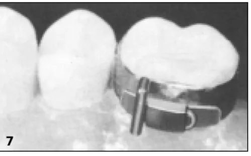
The Clarity bracket was designed with a vertical slot in the base, which allows for greater removal ease. It is beneficial to first remove some adhesive around the base with a flame-finishing bur. After this, band seating pliers can be used to remove the
bracket. It is important that the pliers be held on the outer part of the bracket wings away from the base. The pliers can then be gently squeezed and rocked mesially/distally, which allows the bracket to collapse toward the center.
Removing the Clarity™ Bracket
It is the impression of these clinicians that the goals for the Clarity bracket have been achieved.
1. These brackets show very adequate aesthetics and in general patient satisfaction has been positive in this area.
2. The brackets have demonstrated very adequate strength to allow for proper rotation control and torque control throughout treatment and through the finishing stages of treatment. Overall, very few bracket fractures have occurred in the
prac-tice.
3. The often-dreaded bracket removal process has been much improved, since the brackets, with proper technique, are removed as easily as metal brackets.
Note: The doctors McLaughlin, Bennett and Trevisi exclusively use .022 slot. All their experience with Clarity brackets has been in the .022 slot, primarily in the MBT™ prescription. Clarity brackets are also available in .018 slot and myriad other
Figures 1-6: Clarity™ Bracket removal.
2 3
1
5 6
4
11
Possibilities of Transverse Expansion
Many different strategies exist to realize transverse expansion under a variety of conditions. Some orthodontists think that whether the appliance is fixed or removable, it must inevitably have screws. Others disagree about whether continuous or inter-rupted forces are optimal. Despite these issues, one should never forget that the most important aim in transverse tooth move-ments, as in any other step in treatment, is a fully controlled movement with determined force systems. In addition, there often is a need for more expansion in the anterior segment of the arch than in the posterior. The appliance should be as flexible as possible and ideally, treatment results must not depend on the patient’s cooperation. Lastly, since not every appliance works in every patient as well as it should, especially with the complex biomechanics needed in the transverse dimension, the doctor must be free to easily react to changing conditions. One ideal system to use to manage all the above mentioned variables, is the Unitek MIA Mobile Intraoral Arch Quad Helix System.
Why a Quad Helix ...
... and not a transpalatal arch? Obviously, there is more wire in a quad helix , which means increased elasticity. This elasticity pro-duces the lower load/deflection ratio (Figure 1). In addition, the generated forces become more constant during the course of tooth movement and most of the activation bends remain in the appliance after insertion and are not bent out again.
Figure 1: The quad helix has by far a lower load/deflection ratio than
a transpalatal arch due to the greater length of wire in the appliance.
And Why the Removable Unitek™ MIA
Quad Helix System...
...and not a soldered fixed quad helix? A soldered quad helix, of course, is useful if a custom shape appliance is needed. For exam-ple, if a second premolar is blocked out lingually, insertion of the double end into a MIA lingual sheath becomes impossible. Every other condition can easily be managed with either direct adapta-tion of the appliance or at least by use of the MIA transfer system. The disadvantage of a soldered appliance is the need to remove and reinsert bands and archwires for each adjustment. Much more comfortable, effective and time saving is the use of the Unitek MIA System. Bands with pre-attached MIA lingual sheaths, straight or curved, can be cemented at the usual bonding appointment whether or not a quad helix will be used then or later. In my office, I use prewelded straight MIA lingual sheaths on every upper first molar band, regardless of the treatment nique used (Figure 2), even for patients treated with lingual tech-nique. In adults, one can also use these sheaths on second molars to reinforce cortical anchorage by use of expansion forces. In the mandible, it makes sense to have molar bands with seating lugs only on the lingual side. Since anchorage reinforcements can easily be done with a utility alone (due to the very short dis-tance between buccal root surface and cortical bone) lingual attachments are only indicated for extreme changes in the shape of the arch form or for correction of asymmetries. If needed, a banana-shaped curved MIA lingual sheath is welded onto the lower first molar bands during the bonding appointment. If one is not very familiar with using quad helices in the lower, it may be easier to first seat the fully activated lower quad helix into both bands and then cement them to the teeth together as one unit. This is the same handling as used with a welded appliance. Usually no securing ligatures are necessary, since chewing forces push the frame of the quad helix downward, and the special shape of the lower sheaths plus this downward pushing force always seats the appliance into the sheaths.
Dr. Wiezorek studied dental medicine at Kiel University, Germany from 1987 to 1993. He then finished his thesis and became an associate in a private orthodontic office. In 1995, he was appointed as a scientific assistant at the Orthodontic Department of Kiel University. Since 1997, Dr. Wiezorek has been in private practice in Bad Bramstedt, Germany, with specialization in TMJ treatment, treatment of muscle function, lingual technique, and treatment of children with rheumatic disease. He has served as interpreter and course instructor for Dr. Carl F. Gugino and Dr. R.M. Ricketts at many lectures in Germany, and has given many lectures in Europe and Germany on dynamic biomechanics in orthodontic gnathology and asymmetries, Zero Base
Orthodontics™ and the Unitek™ MIA Quad Helix System.
Enhanced Control in the
Transverse Dimension using the
Unitek
™MIA Quad Helix System
by Dr. Sven G. Wiezorek
12
In both arches, the double end of the Unitek™ MIA Transverse Body is stable enough to withstand the necessary activation needed for totally controlled tooth movement. The amount of activation moments to the arms is normally much greater than usually thought of. This is due to the fact that the double ends function at crown level and the desired tooth movement has to be realized at the center of resistance. To simplify biomechanical thinking, one could think of the point of force application being at the level of the sheaths, even if that’s not exactly the case. The double end and seated lingual sheath act as a fixed connection just as if they were soldered together or manufactured in one
piece. That is why insertion force can never be determined to be at one special point in a continuous and joint free system like the “quad helix double end-sheath-band-tooth” (similar to the “head-gear-buccal tube-band-tooth”, with which many are more famil-iar). Actually the force insertion takes place nearly all over the frame of the quad helix due to its elasticity, which therefore can only be calculated with the finite element method. Nevertheless, to overcome the elasticity of the appliance, activation moments of 45° buccal root torque for maximum cortical anchorage and up to 40° of distal rotation are quite usual.
The Unitek™ MIA System and quad helices may be used in any treatment technique.
Figure 2a: Victory Series™ Brackets. Figure 2b: Conceal Lingual Brackets.
2b 2a
General Problems in More
Complex Situations
Bilateral transversal expansion with various appliances is not very difficult to realize from the biomechanical point of view because unwanted equilibrium forces will cancel out in symmet-ric conditions and pure transverse forces will remain. Controlling tooth movements in the transverse dimension becomes more dif-ficult if an asymmetric maxilla is involved. Real problems will often occur if a situation only seems to be symmetric at first. Especially in those cases where the asymmetry can only be diag-nosed by a three-dimensional biomechanical analysis, which can only be done on casts and never in the patient’s mouth.
Unitek™ MIA Transfer System is an
Optimal Way to Handle Difficult Situations
With the MIA transfer system the exact position of the sheaths in the patient’s mouth can be transferred to metal auxiliary sheaths placed on a cast. Special transfer angles are available to transfer the exact position of the cemented Unitek MIA lingual sheaths to the study casts (Figure 7). Different transfer angles are available for the left and right side, as well as in straight and banana-shaped curves.Figures 3-6: While extruding and retracting
the canines, molar anchorage must be reinforced in the maxilla. Building up cortical anchorage with a quad helix is done by activating it symmetrically with 45° buccal root torque, 6mm transverse expansion and about 20° distal rotation. In Figure 6, notice the mesial arms positioned away from the lingual surfaces of the teeth, thus making distal rotation of the molars possible. Photos taken directly after bonding with round .016 Unitek™ Nitinol SE Wires.
3 4
13
Figure 7: Unitek™ MIA Transfer Angle inserted into the lingual
sheath in the patient’s mouth.
First, bands with Unitek™ MIA Lingual Sheaths are cemented in the patient’s mouth, usually during the full banding. Next, the MIA transfer angles are inserted into the palatal and/or lingual MIA sheaths. Then a standard alginate impression is made. In this impression, one can see the mold of the MIA transfer angle and lingual sheath. The transfer angle can then be removed from the patient’s mouth.
Before pouring the cast, a transfer angle is seated into an auxil-iary sheath. Take care to match the sheath and angle shape. Seat the transfer angle into the sheath; then using pliers; seat both into the impression (Figure 8).
Figures 8a, 8b: Unitek™ MIA Transfer Angle and auxiliary sheath
are seated into the impression.
After pouring the impression, one receives a cast with the MIA auxiliary sheaths exactly representing the position of the lingual sheaths in the patient’s mouth (Figure 9). On these MIA casts the exact biomechanical situation can be diagnosed and all necessary preactivations of the quad helix can be made at the doctor’s convenience with the patient not present.
Figure 9: Cast with Unitek™ MIA Transfer Angle and auxiliary
sheath representing the precise lingual sheath position in the mouth.
Biomechanics Made Easy
The first step in activation of a quad helix or any other transverse mechanical device is to adjust the double ends until they are pas-sive in the MIA auxiliary sheaths. (When I do this, the appliance can look a little bit asymmetric to me. If so, this has nothing to do with asymmetric mechanics; it only indicates that the slot position on both sides is not equal.) From this passive situation we can begin to activate the sheaths.
In case of symmetric bilateral expansion we need about 45° of active buccal root torque since the force insertion is far away from the center of resistance of the teeth. This is the most impor-tant activation for transverse expansion.In addition to this, an expansion of up to 8-10mm can also be activated, but not more. The reason why the buccal root torque is so important, and why the activation for expansion is actually incremental, can be demonstrated by trial activation.
Trial activation refers to the position of the arms with the activa-tion bends in place. If buccal root torque is activated and you take the quad helix with two pliers, one at each sheath, and you carefully bow the double ends into position as if they were to be inserted into the sheaths, you will see that the buccal root torque itself already expresses a certain amount of transverse expan-sion. This is due to the geometry of the appliance. Adding an overly strong transverse expansion activation would only result in the teeth tipping towards the buccal.
Planning the Total Amount of
Transverse Expansion
At the very least, the total amount of transverse expansion that will remain stable after treatment should be pre-planned by cal-culation on a PA head film. As long as the teeth stay in the neutral zone, one can expect the result to be stable. The neutral zone is determined by the width of the apical base, and the equilibrium of forces from tongue and cheek muscles (Figure 10). This drawing of the functional neutral zone cannot fully illustrate this complex theme. Complete determination would require analyzing the EMG-potential of the chewing muscles, a PA head film, a TMJ evaluation, and an examination of tongue posture. Nevertheless, if you move out of this zone towards the buccal or the lingual, you will have to develop a special retention appliance, since biologi-cal laws cannot be overcome even by the best mechanibiologi-cal system.
Figure 10:
Determining the func-tional neutral zone. 1) Using a PA headfilm, determine the maxil-lary-mandibular rela-tion (green arrows, measured from lower first molar to frontal denture plane), which has a normal value of 10 mm +/- 2 mm. 2) Determine the molar relation (yellow arrows), which is 6 mm +/- 2 in normal conditions. These two parameters with their
7 8a 9 8b 10 continued on page 14
14
Figure 14: Distal rotation is easy with a Unitek™ MIA Quad Helix.
Figure 15: Asymmetrical activation moments in the transverse plane will generate sagittal equilibrium forces.
Figure 16: Distal rotation on one side and mesial rotation on the other will enhance mesiodistal movements, but can be difficult to handle intraorally.
Figure 17: Notice the mesial rotation activation on the one arm and the distal rotation activation on the other, to generate a mesial force at the
side of distal rotation activation and vice versa.
Figures 18-21: Notice the full segmentation of the arch with utility mechanics. To reduce unwanted rotation, .0162Unitek™ Flexiloy Wire segments are built bilaterally from 7 to 3. The activation on the left side is distal rotation without buccal root torque. The right side activation is mesial rotation and 45° buccal root torque, in order to generate cortical anchorage so that this molar will not move distally.
17
Figure 11: In symmetric activation, the intrusive and extrusive equilibrium forces of both moments cancel each other out. Figure 12: If an asymmetric activation is present, vertical equilibrium forces will remain.
Figure 13: Shows an asymmetrically activated Unitek™ MIA Quad.
12
13
11
14 15 16
clinical deviation determine the skeletal basis for the functional neutral zone (gray area). The functional neutral zone is a modification of this skeletally-determined zone taking into account additional functional parameters.
The functional neutral zone is the area where the pressure of muscles from the buccal and from the lingual side are equal over a period of time. For example, a hypotonic tongue will make it difficult to establish a stable transverse expansion, because the functional neutral zone is closer to the facial midline (blue arrows), as does a low tongue posture which cannot create buccal forces on the upper molars. While tongue activation potential is very difficult to measure on a routine basis, EMG measurements of m. masseter and m. buccinator can easily be done. Any activation potential on the EMG monitor of more than 20 mV at rest will indicate these muscles are hypertonic. This means that the functional neutral zone for each side is closer to the midline. If transverse expansion is important under these conditions, the doctor has to take care to ensure enhanced retention. If the masseter-buccinator complex is maintained in equilibrium, it will bring the functional neutral zone more to the lateral side, thus improving stability after expansion. This equilibration can be done by means of special physiotherapy or by EMG feedback training.
(Figure 10, continued)
19 18
15
Biomechanics of Asymmetric Corrections
In order to discuss asymmetric corrections, we have to simplify our way of looking at the appliance. At first we assume the point of force insertion to be at the Unitek™ MIA Lingual Sheaths. Second we only want to look at a bidimensional system in the frontal plane. With these preconditions it becomes quite easy to understand unwanted vertical side effects during expansion: Symmetric buccal root torque is achieved, if the angle of activa-tion between lingual sheath and double ends is the same on both sides (Figure 10). At both sides, a moment of a couple (MC) is activated which produces an intrusiveequilibrium force at the same side and an extrusive equilibrium force at the other. Since both of the moments are equal, their equilibrium forces are equal, too and cancel out.
As soon as the angle of activation becomes greater on one side, some vertical equilibrium forces will remain in place and will produce vertical tooth movements, which are usually unwanted (Figure 11). This situation can occur in the mouth if one molar is more upright than the other. Use a MIA cast to recognize these asymmetric conditions and to prevent vertical side effects. In very few cases, these vertical forces may be what we want, for example in lateral open bites. While the MIA’s vertical equilibri-um forces can be used to help bite closure, the quad helix should never be used as the sole mechanism. Since there are always equilibrium forces present from both arch arm activations, we have to know whether the resultant equilibrium is intrusiveor
extrusive at one side. The bigger activation moment will deter-mine the direction of the resultant equilibrium.Thus for extru-sion of the right molar, maximum buccal root torque has to be activated at the left molar. But, never try to enhance the extrusive
forces by activating palatal root torque at the extrusion site. The only movement you will get is somewhat of a tipping and shift-ing of molars, and conversely, no extrusionwill result at all.
How about Distal Rotation?
Distal rotation of the upper molars is often a very pleasing tooth movement that helps correct a Class II occlusion. With symmet-ric activations, (i.e., symmetsymmet-ric angles of activation between sheaths and double ends), distal rotation of the molars can more easily be realized with a Unitek MIA quad helix (Figure 13) than via continuous wires.
Asymmetrical activation moments generate sagittal equilibrium forces (Figure 14). This can be helpful in unilateral space closure. Activating distal rotation on one side and mesial rotation on the other (Figure 15) can even enhance sagittal forces. But normally this system is very difficult to handle in the mouth. The arches must be fully segmented in order for these mesiodistal move-ments to really take place.
Summary
With the Unitek™ MIA Quad Helix System, a system for quick transverse mechanics exists, which is very easy and time saving to handle. An inventory of molar bands can be prepared with MIA lingual sheaths on a routine basis to allow the insertion of a MIA quad helix whenever necessary. More complex situations or asymmetric conditions can be managed by use of the MIA trans-fer system and MIA casts. ■
Zero Base Orthodontics is a trademark of Dr. Carl Gugino. Unitek is a trademark of 3M Unitek.
20 21
control your inventory. We are now many revisions down the road from that earlier program. With Y2K we are introducing the latest and greatest with many additional features that continue to set 3M Unitek sales representatives apart from the rest of the industry.
In the coming year we will better communicate the many other programs available to our valued customers through our Professional Relations Department. Programs such as: Alliance, which offers preferred order processing features, practice devel-opment seminars with renown speakers; MatchMaker, which is a state of the art program that matches graduating orthodontic res-idents with doctors who are looking for an associate or buyout option; and Solutions by Design, providing you with important marketing support.
Of course, you will still be able to rely on your field representa-tive for technical assistance in product selection and we will continue to lead the industry with our training program to achieve that goal. But we have heard time and again that you want our people to have a better overall understanding of the day to day operations of your business so that you can learn how to run the most effective, efficient practice possible. It is to that end that we are committed. We plan to continually seek your input and thoughts on how we are doing in achieving that goal. If you wish to share your ideas please feel free to contact me directly. I look forward to sharing our success stories with you in the months to come and wish you the best for the New Year and the new century. ■
Consultative Selling/The Next Generation
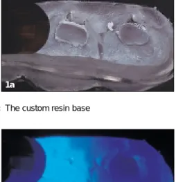
continued from page 2Curing the Custom Resin Bases
It is not necessary for a doctor to own a TRIAD light curing chamber to use Sondhi Rapid-Set Indirect Adhesive. If you are using a TRIAD light curing chamber, make certain that it is the new model with the rotating table. The TRIAD light curing cham-ber is certainly more time efficient and is not very expensive (approximately $450-500). However, using an Ortholux™ XT Curing Light is just as effective, but this is more inefficient. We found that while the model is automatically curing in the TRIAD light curing chamber, we can complete other laboratory tasks.
Figure 1a: The custom resin base
Figure 1b: Curing the Custom Resin Base using an
Ortholux™ XT Curing Light
If you prefer to use the chairside light curing unit, it is vital to remember that you are curing the resin between a metal surface and plaster. Curing on plaster is different than curing on enamel, so it takes much longer to cure the resin. It is important to cure each custom resin base again for an additional 10 seconds to ensure that the adhesive is cured.
It is critical to note that once the tray is removed, and before any cleaning of the tray or the resin bases is done, the resin bases should be exposed to light for an additional period to minimize the risk of bond failure through inadequate curing of the custom resin base on the stone model. You can fully cure the base by put-ting the tray back in the TRIAD light curing chamber for one minute. Or, if you are using a chairside light curing unit, we would suggest direct curing of every resin base for an additional 10 seconds each, to ensure that the adhesive center is completely cured (Figures 1a, 1b).
Cleaning the Resin Bases
It is important that the resin base should be extremely clean to permit a good bond, but you should be careful not to abrade the resin base. Micro-etching with the 50 micron powder is certain-ly recommended by Dr. Sondhi, but should be done for oncertain-ly a short period of time. As a general rule, 1 to 2 seconds should be sufficient. If you continue to micro-etch for an extended period of time, you will abrade away some of the resin and increase the chance of bond failure. If a micro-etch unit is not available, then a thorough scrubbing of the resin base with a toothbrush and detergent, is an alternative.
We have found that the use of acetone must be handled carefully, or it may create more problems than it solves. If acetone sits on the resin for even a few seconds, it can cause the resin surface to deteriorate. A telltale sign of resin deterioration is the appearance 16
Bob Stanley has been a member of the Sondhi lab staff for 21/2years. He has been
an orthodontic lab technician for 91/2years.
Laboratory Procedural Enhancements
to the Sondhi
™Indirect Bonding System
by Robert Stanley, Laboratory Technician and Stephanie Luke, Clinical Assistant – Sondhi Orthodontics, Indianapolis, Indiana
Stephanie Luke has been a member of the Sondhi clinical staff for almost 2 years and has been in orthodontics for almost 10 years. She attended the IU School of Dentistry Clinical Assisting Program.
1a
1b
Indirect bonding systems are always technique sensitive. Our office participated in the development of the Sondhi™ Rapid-Set Indirect Bonding System, which was introduced at the AAO in San Diego. Over the past few months, we have learned a few things that enhance the consistency and effectiveness of the system. Now it’s time to sit down and summarize some of the ideas, questions and suggestions that we’ve received from doctors, clinic assistants, and laboratory technicians. Listed below, in no particular order, are some ideas that you may wish to consider.
17 of small white spots on the resin base. The white spots usually
indicate that too much acetone has been applied to the custom resin base, which could lead to bond failures. Because of this, we no longer use acetone in our lab. We either micro-etch or use a toothbrush with detergent to clean the resin bases.
Tray Layer Fabrication and Lubrication
When Dr. Sondhi’s article on this technique was first published in the AJO-DO1, a different thickness of tray material was beingused. It is now evident that the 1.5mm thickness of the softer Bioplast® Layer and 0.75mm thickness of the stiffer Biocryl®
Splint, shown in the video, are much more effective.
Ever since we started using the PAM®spray on the brackets, we
have found it unnecessary to use Mor-Tight®. Plus, our newest
technique improvement is the addition of a 1 to 2 second spray of PAM between the formation of the Bioplast and the Biocryl layers, so that the separation of the two layers is much easier, Figure 2.
Figure 2: Lubricating between the Tray Layers facilitates separation
Forming the Tray
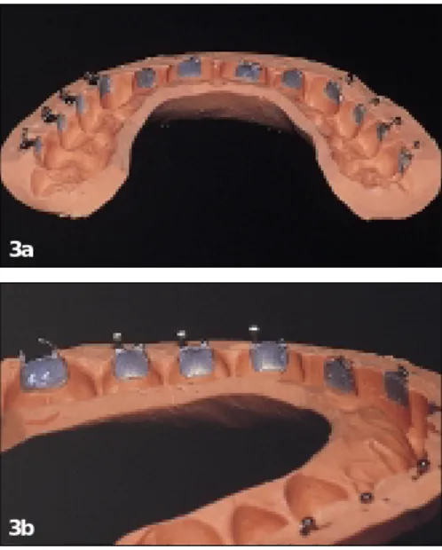
It is notnecessary that a doctor wishing to try our system obtain a Biostar. Indeed, it is entirely possible for a doctor to use this system with an indirect bonding tray formed with putty, such as 3M™ Express™ Polyvinylsiloxane Impression Material, Figures 3a, 3b. In the video, we emphasized the use of a clear Biostar tray, since it allows greater precision, and a clear tray permits more accurate visualization of the tray seating process. Doctors shouldn't be discouraged from trying the system simply because they are reluctant to acquire a Biostar. We know several doctors who have used the putty and wash system on hundreds of patients, and appear to be quite satisfied.
Figures 3a, 3b: A Putty Tray
As we continue to learn from practitioner’s suggestions, we wel-come ideas to make indirect bonding simple and easy to use. ■
2
3a
3b
1 Sondhi, Anoop: Efficient and Effective Indirect Bonding. Am J Orthod
Dentofacial Orthop 115:352-9, April 1999 3M and Express are trademarks of 3M Company. Biocryl is a trademark of Great Lakes Orthodontics. Bioplast and Biostar are trademarks of Scheu-Dental GmbH. Mor-Tight is a trademark of TP, Inc.
PAM is a trademark of International Home Foods. Ortholux and Sondhi are trademarks of 3M Unitek.
The desire to cure on demand is driving an increasing number of orthodontic practices to utilize light cure adhesives instead of the more traditional two paste adhesives requiring in-office mixing. The introduction of light cure adhesives not only removed a step in the bonding procedure, but also allowed practitioners the free-dom to choose when to initiate the adhesive curing cycle after bracket placement. The orthodontic community then took anoth-er step towards ideal bracket curing with the introduction of high intensity plasma arc and laser curing lights. These lights offer the orthodontist a significant reduction in bracket cure time over conventional curing lights. However, each practitioner must weigh the benefit of the decreased cure time against the substan-tially higher cost.
To help our customers keep abreast of developing curing light technology 3M Unitek tested two high intensity curing lights, the Apollo 95E from Dental / Medical Diagnostics (Woodland Hills, CA) and LaserMed’s AccuCure 3000™ (LaserMed, Salt Lake City, UT). Both of these lights have been shown to work well with 3M Unitek adhesives, however their operation is slightly different and the right choice for an office may depend on the bonding procedure.
Background
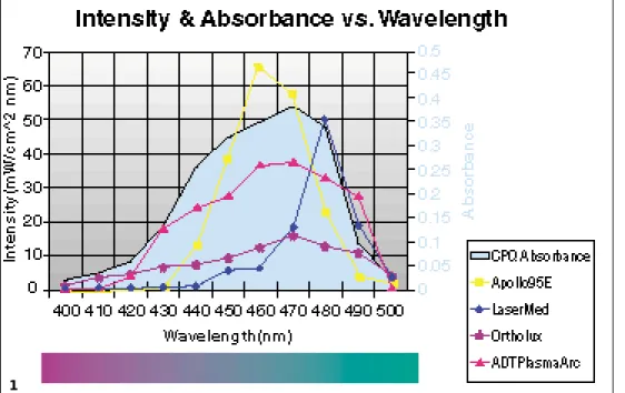
All orthodontic adhesives contain liquid chemical monomers, which must be chemically reacted to form a polymer network. This curing reaction solidifies the adhesive and gives it high strength. In light cure adhesives, this process begins when a pho-toinitiator is activated. All 3M light cure adhesives contain cam-phorquinone (CPQ) as the photoinitiator. CPQ absorbs blue light, which has a wavelength between 400 and 500 nanometers. The new high intensity plasma arc and laser curing lights provide blue light with higher brightness, which accelerates the curing reaction. The light absorption curve for CPQ and the emission curves for several curing lights are shown in Figure 1.
Conventional Curing Lights
Conventional Curing lights use a halogen lamp to generate a white light which is then filtered so that only blue light in the 400 to 500 nanometer range is emitted from the tip. The Ortholux™ XT Curing Light (3M Unitek, Monrovia, CA) is an example of a conventional orthodontic curing light (Figure 2). Its light intensity profile is shown in Figure 1. Cure times out-lined in 3M Unitek adhesive bonding instructions are based on curing with a conventional halogen curing light such as the Ortholux XT curing light. 18
High Intensity Curing Lights
by Jim Hansen, Ph.D., Product Development Supervisor and Brian Lotte, Technical Service EngineerJim Hansen received his Bachelor of Science Degree in Materials Science and Engineering from the University of Minnesota in 1987. In 1991, he received his Ph.D. in Materials Science and Engineering from Northwestern University. Since 1991, he has worked in Research and Development at 3M Unitek. Currently, he leads a group of scientists developing new adhesive, elastomer, and wire products.
Brian Lotte joined 3M Unitek 2 years ago after graduating from U.C. Santa Barbara with his Bachelor of Science Degree in Mechanical Engineering. Since 1997, he has worked in Technical Services organizing clinical trials for new product development.
2
Figure 1: CPQ Absorbance and Curing Light Intensity vs. Wavelength 1
Figure 2: Ortholux™ XT Curing
19
Plasma Arc Curing Lights
The mechanism of plasma arc light genera-tion is new to the orthodontic community. The light source in a plasma arc unit is a Xenon bulb that functions very similar to the commonplace object pictured in Figure 3. Two probes create a large voltage poten-tial that ionizes the gas (plasma) and creates a spark, which emits light (arc). NASA orig-inally developed plasma arc technology to test re-entry heat shielding for space vehi-cles by creating a spark between a probe and the shield. Since then, the technology has evolved into projection equipment and medical instruments.
The Apollo 95E from Dental / Medical Diagnostics (Woodland Hills, CA) is an example of a plasma arc light (Figure 4). The lamp produces a high intensity white light that is filtered to only allow blue light in the 400 to 500 nm range. The light intensity profile for the Apollo 95E is shown in Figure 1. The total amount of blue light emitted is several times greater than with the Ortholux™ XT curing light. A timer on the light limits sin-gle exposures to a maximum of three seconds with each activa-tion and provides a 1.5 second latent period during which time the light cannot be activated. This prevents excessive tissue heating which can occur with over-exposure.
The unit cures individual brackets slightly faster than the LaserMed unit, however the latent period may impede progress when consecutively curing brackets. This unit is well suited for offices using a bonding procedure where a staff member follows the orthodontist around the arch as each bracket is placed in its final position. The DMD unit could also be used where the orthodontist places a
bracket with one hand while using the other hand to cure.
Figure 4: Apollo 95E
(DMD)
Argon Lasers
Argon lasers emit a blue light with a very narrow wavelength dis-tribution. An example of a laser curing light is the LaserMed AccuCure 3000™ (LaserMed, Salt Lake City, UT); a product pho-tograph is shown in Figure 5. The output of this laser is also shown in Figure 1. Lasers are capable of emitting a collimated beam of light that can travel long distances without dispersing. The LaserMed light features a dispersive lightpipe tip that diffuses the light emitted from the unit into a cone of light, which is ideal for orthodontic appliance curing.
The LaserMed unit will emit light for as long as the foot pedal is depressed. An audible tone sounds every five seconds to keep track of curing time. The “continual on” operation lends itself to curing many brackets consecutively. This light delivery system is particularly useful when a latent period is undesirable, such as “tacking” many brackets in a row. The light guide is constructed from a glass fiber optic instead of a liquid cable like the plasma arc units. The lighter, thinner fiber optic construction results in a more maneuverable light guide that facilitates curing posterior appli-ances. However, it must be noted that laser lights are subject to
more government regu-lation than other types of blue light sources and proper warning signs should be placed in the operatory.
Figure 5: AccuCure
3000 (LaserMed)
Results with 3M Unitek Adhesives
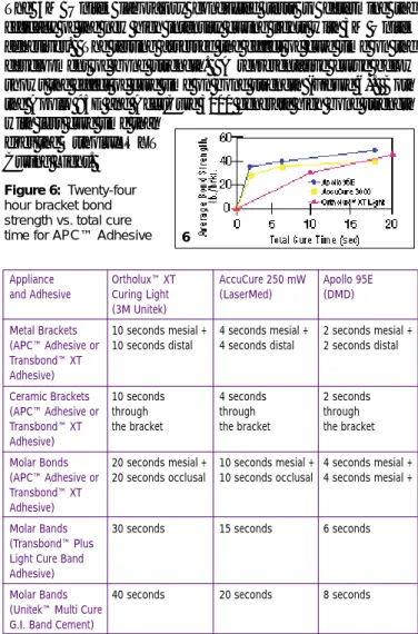
The 3M Unitek laboratory conducted tests to determine the efficacy of the new high intensity curing lights with 3M Unitek adhesives. The testing assessed the effect of cure time on the development of bond strength. A representative curve below shows the effect of cure time on bond strength (Figure 6). Both the Apollo 95E and AccuCure 3000 generate high bond strength with less cure time than
does the Ortholux™ XT Curing Light.
Figure 6: Twenty-four
hour bracket bond strength vs. total cure time for APC™ Adhesive
Summary
The Apollo 95E plasma arc light and the AccuCure laser both save time during the bonding procedure while producing an equivalent bond to the conventional curing lights. The operation of each of the units is different, and the correct choice will depend on each office’s bonding procedures.
The true value of High Intensity Curing Lights is the significantly reduced chair time endured by anxious patients during a full bond-ing procedure as well as the convenience and simplicity offered to the staff, especially when used with brackets pre-coated with adhe-sive. The marriage of quick cure lights with the APC™ Adhesive Coating System offer the ultimate in bonding efficiency. ■
AccuCure 3000 is a trademark of LaserMed Corporation. APC, Ortholux, Transbond and Unitek are trademarks of 3M Unitek.
3
Appliance Ortholux™ XT AccuCure 250 mW Apollo 95E and Adhesive Curing Light (LaserMed) (DMD)
(3M Unitek)
Metal Brackets 10 seconds mesial + 4 seconds mesial + 2 seconds mesial +
(APC™ Adhesive or 10 seconds distal 4 seconds distal 2 seconds distal
Transbond™ XT Adhesive)
Ceramic Brackets 10 seconds 4 seconds 2 seconds
(APC™ Adhesive or through through through
Transbond™ XT the bracket the bracket the bracket
Adhesive)
Molar Bonds 20 seconds mesial + 10 seconds mesial + 4 seconds mesial +
(APC™ Adhesive or 20 seconds occlusal 10 seconds occlusal 4 seconds mesial +
Transbond™ XT Adhesive)
Molar Bands 30 seconds 15 seconds 6 seconds
(Transbond™ Plus Light Cure Band Adhesive)
Molar Bands 40 seconds 20 seconds 8 seconds
(Unitek™ Multi Cure G.I. Band Cement)
Table 1: Recommended Cure Time for Various Appliances, Adhesives and Curing Lights
4
5
6 Figure 3: Spark
3M Unitek
3M Dental Products Division 2724 South Peck Road Monrovia, CA 91016 USA
3
Unitek
Products that make your life easier.
Have technical questions?
3M Unitek Technical Hotline, (800) 265-1943
In Canada (800) 443-1661 ext. 4413 012-123 9910
New Double and Triple Victory Series™
Buccal Tubes, MBT ™ Rx
Utilizing segmented arch mechanics no longer means patient discomfort due to bulky, multiple archwire buccal tubes. The new triple and double buccal tube addition to Victory Series Buccal
Tubes, in the fast growing MBT Prescription, not only look great, but will also reduce patient discomfort complaints. They were designed to utilize the prescription advantages of MBT, which addresses the clinical needs of the posterior segment. Fully contoured, the smooth corners and sides and a smooth rounded hook, along with a lower tie-wing profile, assures greater comfort. At the same time, features like beveled and con-toured mesial and distal notches and an expanded mesial funnel entry mean easier ligation and archwire insertions.
Available on all 3M Unitek Molar Bands. Also, the lower double tube is available on the Victory Series Bonding Bases with the option of APC™ Adhesive Coating System.
Clarity™ Metal-Reinforced
Ceramic Brackets in High Torque
and Standard Edgewise Rx
Clarity brackets, the only brackets to deliver the aesthetic bene-fits of ceramic with the functional advantages of metal brackets, are now available in both High Torque and Standard Edgewise Prescription. The real beauty of Clarity brackets lies in its supe-rior functionality. No other ceramic bracket performs like the Clarity bracket, because no other ceramic bracket provides a metal-lined archwire slot. This design raises Clarity bracket’s sliding mechanics to a performance plateau equivalent to metal brackets. Smooth accurate tooth movement is assured at every point in treatment, through to your finishing archwire. And, no change in mechanics is required.
You can bond and de-bond Clarity brackets using the same procedures as metal brackets, and expect the same result. Bonding can be performed with light cure or chemical cure adhesive systems. Or, for the ultimate in convenience, you can choose APC™ Adhesive Coating System.
Unitek™ Beta III Titanium Wire
Unitek Beta III titanium wire is thehappy medium between nickel titani-um and stainless steel. Beta III is made to 3M Unitek’s award winning stan-dard of quality. It features a smoother surface for improved sliding
mechan-ics. It is carefully processed to increase fatigue resistance, which means reduced breakage during bending and activation. And, Unitek Beta III’s tight corner radii specification allows you to take maximum advantage of the prescription built into your appliance system, especially when finishing a case.
Solutions by Design™ Direct
Mail Marketing Solutions
Solutions by Design has recently introduced a new direct mail marketing program. As a tactic in an SBD marketing program or as a stand alone effort, Direct Mail Marketing Solutions can be a most effective means of building awareness in your market, gaining market share and enhancing your practice’s bottom line. This turnkey flexible program can target service niches such as aesthetic braces featuring 3M Unitek’s Clarity aesthetic brackets or Victory Series Gold brackets. Available in four full-color series, the program will be limited to one series per client per market.
New Price Reduction on
CD-ROM Journal Archives
CD-ROM journal archives let you look at your journals from a new angle. The AJO-DO, JCO,
and Angle Orthodontistare offered in both WIN-DOWS®and MACINTOSH® format. These
jour-nals are the ultimate in portability, time saving and space. To make them easier to obtain, 3M Unitek has just reduced journal pricing.
Call your local 3M Unitek representative for information. ■